Sukhoi Su-57 flight testing, development & operations [2012-current]

Yes, the naval Tejas, aka Navy LCA or LCA (N). Its development was halted in favor of the TEDBF, with the Rafale Marine being purchased in the meantime.

So what we have now ? Where are the other fighters with that LEVCONs except Su-57 as the only operational fighter with them? Tejas in naval version was cancelled,those many concepts stayed only the concepts ....

Btw, LEVCON's on the Su-57 are not only the simple aerodynamic control surface.It has inside of it long range L-band AESA N036L. So those LEVCON's have practically dual role for the Su-57.

View: https://www.reddit.com/r/WarplanePorn/comments/sjlxy8/a_new_pair_of_serial_production_su57s_no02_and_52/#lightbox
 
Every time I hear or read that the LEVCON concept is unique to the Su-57, I can't help...
(Plus a handful of unflown Northrop MRF studies.)
There's plenty of NASA work on variations of it too from the 70s / 80s if you look

Everything is a trade off into whether a particular feature makes its way onto an aircraft or not
 
On the previous page we have now almost complete translation of the doc. about the Project 'The Scale' that is in connection with the development of the decimetric L band AESA N036L. I forgot that I have some translations of the articles from 2008/2009/2010/2011 about those L band AESA. Here they are:

These are the test results conducted about 20 years ago ( real tests of the L-band AESA prototype antenna in NIIP named after V.V Tikhomirov) .Source is one article of NPP 'Pulsar' from 2008. Mentioned before the model of L-band AESA was first publicly shown on MAKS-2007.


The main problems of creating TRM's for the L-band AESA

''
One of the important components of the L-band AESA is the transmit-receive amplifier module (TRAM), designed to amplify transmitted and received radio pulses.The main problem in creating such a module is the need to implement highly efficient transmission channels with a total output peak power of about 1800 W per four channels with a useful module volume of approximately 2.5 l . In addition to amplifying the input radio pulses to the required level with the required gain, an equally important requirement is the least distortion (deterioration) of the spectral, temporal and noise characteristics of the input radio pulses. The main technical requirements for the receiving and transmitting channels of the PPUM/TRM and the measured characteristics of the model of the TRM are given below in Tables 1 and 2, respectively. The measured values of the characteristics of the breadboard are given for all four channels of the module.


Table 1

Basic technical requirements for the receiving channel of the TRM

Name of parameters : Frequency range, GHz ... Technical requirements : 1.2-1.6 , Measured parameters of the test model : 1.2-1.6
Noise figure, dB ... Technical requirements : 3 , Measured parameters of the test model :1.5-2.3
Transmit coefficient, dB ... Technical requirements : 29-35 , Measured parameters of the test model :36.7-39.3
Unevenness of the transmission coefficient, dB Technical requirements : no more than 2 , Measured parameters of the test model : 0.6-1.3
Gain adjustment depth, dB ...Technical requirements : -15.5 , Measured parameters of the test model : -15.5
Discreet adjustment of the transmit coefficient, dB...Technical requirements :0.5 , Measured parameters of the test model 0.5
VSWR input of the receiving channel ....Technical requirements : no more then 2 ,Measured parameters of the test model : 1.1-1.8

Table 2

Basic technical requirements for the transmitting channel of the TRM

Name of parameters: Output impulse power, W ..Technical requirements : no less than 300 ( for radar mode) and 400-500 ( for IFF mode) ,Measured parameters of the test model : 360-540 ( for radar mode) and 330-480 ( for IFF mode)
Chip of radio pulse, dB..Technical requirements : no more than 0.3 ( for radar mode) and 0.6 ( for IFF mode) ,
Measured parameters of the test model : 0.2-0.7 ( for radar mode) and 0.3-0.5 ( for IFF mode )
The spread of the output power between channels, dB...Technical requirements : no more than 1.0 , Measured parameters of the test model : 1.1 ( for radar mode) and 0.8 ( for IFF mode)
Depth of step electronic output power level control, dB ....Technical requirements :3-5 ( for both modes) ,Measured parameters of the test model : 2.8-4.8 ( for both modes )
The duration of the front of the radio pulse, ns(nanosec).. .Technical requirements : no more than 150 ( for both modes) , Measured parameters of the test model : 100-250 ( for radar mode) and 25-130 ( for IFF mode)
The duration of the falloff of the radio pulse, ns ..Technical requirements : no more than 150 ,Measured parameters of the test model : no more then 30 ( for both modes )
VSWR at the input of the transmitting channel...Technical requirements :no more than 1.5 ,Measured parameters of the test model : 1.2-1.6 ( for both modes)
Efficiency( Duty Cycle ) of transmission channel,% ...no less than 20 , Measured parameters of the test model: 25-32 for the radar mode.
Note: frequency range ΔF2 (radar mode) - τ = 10 μs, Q = 20; frequency range ΔF3 (IFF mode) - τ = 32 μs, Q = 100 .''

It is interesting that Carlo Kopp wrote in his article from 2009 that Duty Cycle is ~20% but several years earlier ,the test model ( prototype of L-band AESA) had 25-32 % of the DC .

From another article ( 2009 ) :

L-band multichannel broadband microwave transmit-receiver module for airborne radar with AESA .

''The modules are 4-channel, each TRM includes a signal processor that controls the amplitude and phase of the TRM , as well as primary information processing. The output power of the TRM is hundreds of W, the capacity of the phase shifters is from 5 to 7 digits, the range the adjustment of the attenuators is about 25 dB.Overall dimensions (HxWxD), no more: 70x1650x90 mm, which are additionally limited by the shape of the available space under the nose fairing .The features of assessing monostatic and bistatic AESA are considered. Numerical algorithms have been tested and a diagram of the backscattering of a phased array from log-periodic and monopole emitters of the decimeter range with an operating frequency range of 1 ... 1.6 GHz is presented when irradiated with a wave of the centimeter range in the band 8.5 ... 12.5 GHz. It is known that the sweep angle of the Su-57 wing is approximately 48°, therefore, to view the radar in the forward direction, it is necessary to deflect the beam at least by the same angle. Max Pulse power per element 500W. Average power per element 250W .The preferred number of elements in the radiating system is 12.''


This is another article about L-band AESA ( also from 2009 );

ON-BOARD LINEAR AESA OF DECIMETRIC BAND

''When placing antennas together decimeter and centimeter wavelengths, a number of problems arise - a largewidth of the radar beam of PESA-AESA for IFF does not allow obtaining a sufficient angular resolution. Moreover, combining emitters of two AESA in a single aperture causes mutual distortion of antenna characteristics. When switching from passive ESA to AESA , difficulties arise in combining two antennas inone aperture. Therefore, the question arises about the possibility of autonomous execution of AESA IFF.In the course of a detailed analysis of the surfaces of modern and future aircraft, it wasrevealed that the most promising is the placement of the AESA IFF in the leading edge of the wing. A rather extended aperture with a length of up to 10λ can be placed in the wing tip, which will be able to provide the required angular resolution in one plane - in azimuth. In practice, this is quite sufficient, despite the lack of angular resolution in the plane elevation angle.In addition, there is the possibility of placing on board not one, but two AESA , which expands the scanning sector of the radar- IFF antenna.

Considering that the constituent AESA blocks have sufficient broadband, AESA can perform the functions of multiple antennas. Considering the positive aspects of placing the IFF antenna in a movable nose wing, do not forget about the strict restrictions on the overall dimensions of the blocks,imposed by such an extraordinary placement. Temperature conditions at variousflight modes and mechanical effects on the blocks create additional difficulties fordevelopers.For example, the temperature in the leading edge of the wing tip can reach + 180°С,and the mechanical loads ( g load) are at least 5.5g. Therefore, special attention waspaid to the development of the emitter, which should form a given DN, taking into account the influence of closely spaced fairing and maintain performance in harsh climatic conditions.Autonomous placement of the IFF antenna assumes a fairly long cable network.

Considering the amount of attenuation in the coaxial conductor, to ensure the requiredenergy parameters, it is necessary to install a powerful transmitter on board. It has becomeone of the reasons for the implementation of the IFF antenna using the AESA technology is the inclusion in the antenna active module.The classic performance of the active modules that make up the AESA assumes monolithic design options. In most cases, it is justified, however, when working in the decimeter wavelength range, the dimensions of the module become rather bulky.Therefore, the AESA IFF is built according to the following scheme: the signal received by the emitting systemamplified in the receiving channel of the module, phase shifters made by a separate device,provide the necessary phase shift in each channel, then the signal from each channelsummed in power dividers. AESA is controlled by the control unitantenna (ACU), the main task of which is the calculation of phase codes and controlphase shifters AESA, i.e. providing electronic scanning with a beam.

All feeding voltages are supplied to the units from a secondary power source.AESA modular design allows compact placement in one wing compartmentactive modules, and in the other - distribution and phasing devices (URF), anddiagram-forming device (DOU). In addition to being compact, such a construction schemeallows you to easily switch from the active version of the antenna to the passive ESA( from AESA to PESA ) , by means of simple exclusion of the amplifier modules from the circuit. All other blocks designed inNIIP are based on proven technologies and can be used for its intended purposein almost any version of the PAR (phased array radar ) . Description of the construction of blocks and their characteristics are given in the full text of the report.The main stages of setting up / working with AESA are:- measurement of the characteristics of active (transceiver) modules;- writing to the flash-memory of control devices (CU) of the necessary correctingdummies allowing to control the amplitude-phase distribution (AFD);- checking the AFD at the output of the amplifier modules as part of the AESA;- mathematical modeling of AESA characteristics using special software forthe results of measurements of the AFD;- measurement of characteristics of radiation AESA.

The measurement of the characteristics of the amplifier modules is carried out in order to compensate for differences between the module channels in phase incursions and the implementation of a given amplitudedistribution. The values of the phase raids of each channel of the module, and the required attenuation value to create a given amplitude distribution( AR ).For this, a four-bit attenuator is installed in the receiving channel of the module, and inthe transmitting channel is provided with a stepwise adjustment of the output power level.The processing of the phases recorded in the CU is carried out by the URF phase shifters.Verification of the accuracy of amplitude-phase distribution-AFD implementation is carried out taking into account the cable network. More details about the verification process are described in the full report. According to the results of measurements of the AFD the expected characteristics of the study of AESA are calculated.At the moment, NIIP has manufactured, configured and tested a sample of AESA-IFF .The sample is made on the basis of an emitting system of 12 emitters combined in three blocks, three 4-channel amplifier modules( TRM), two six-channel distribution and phasing devices and diagram-forming device.The transmission of microwave power between the units is carried out by coaxial cables.''

So this article from 2009 confirms that tests occurred earlier ,in 2008 maybe even earlier as mentioned before and that was in fact model-prototype of L band AESA ( radar and IFF ) for Su-57 in NIIP .This is a very interesting detail :

'' A rather extended aperture with a length of up to 10λ can be placed in the wing tip, which will be able to provide the required angular resolution in one plane - in azimuth. ''

So that kind of antenna could be 240cm in width ( λ=24cm x 10λ ) but instead of that solution ,they made and installed 4 antennas with width of about 160cm in LEVCON's tip and in wing slats tip . There are more technical and tactical possibilities with 4 rather than 2 antennas . As written before, these 4 bigger antennas have two waveguides . One ( upper) for emitting signals when LEVCON's and wing slats are in the lower position and another row ( lower) for emitting signals when LEVCON's and wing slats are in the neutral position.

Advertisement from the MAKS2009

''At the MAKS-2009 air show, at the stand of the Tikhomirov Research Institute of Instrumentation, L-band AESA will also be demonstrated. Designed to fit into the deflectable wing tips of a fighter jet. It is also made on modern hybrid-integral domestic technologies and provides electronic scanning by a beam in a wide sector of angles in azimuth and in a wide frequency band. This locator, like the X-band AESA, was assembled at NIIP, where a unique laboratory testing base was created for this, including anechoic chambers equipped with the latest modern technology.The use of the L-band in air-to-air radar operation is the T-50's primary task of detecting stealth aircraft ''

Then there are some NPP Pulsar articles from 2010/2011 about the modernisation and upgrading of those TRM:

MODERNIZATION OF A POWERFUL L-BAND ON-BOARD AESA MODULE

''The module of the initial development was presented at the Pulsar-2008 conference, and is now being mastered in production. The issue of its modernization is a response to the requirement for a prompt increase in the level of operational characteristics, which is typical of rapidly developing areas of technology.The main goal of the upgrade is to increase the output pulse power level from 400 W to 700 W in a record frequency band of 1 -1.5 GHz in each of the 4 channels of the module. At the same time, the overall and connection characteristics of the module remain unchanged.
The modernization is based on a new generation of integrated assemblies called “power amplifiers” to replace powerful microwave transistors, as well as the development of the principle of volumetric integration.The upgraded module is a transceiver with a noise factor in a given band of no more than 4 dB. A variant of constructive upgrade of the housing is considered in order to improve the technological efficiency of assembly, control and repairability.
In terms of the parameter specific output pulse power per unit of module volume, the obtained result (2 kW/l) exceeds known world achievements.''

ELECTRICAL AND FUNCTIONAL CHARACTERISTICS OF THE UPGRADED MODULE FOR THE L-BAND AIRBORNE AESA

I.V. Korenkov
FSUE NPP Pulsar, Moscow

''The module developed and supplied to the customer is characterized by a high level of output power (400 W per channel), wide bandwidth (1 – 1.5 GHz), and high functional capabilities.The main ones are: high sensitivity in reception mode (noise factor less than 4 dB), the presence of a secondary power source (SPS) with high voltage stabilization rates, multi-level built-in control, ensuring operation in a wide temperature range (from –60°C to +70°C), control of the phase of the received and transmitted signals.During the production and operation of the module, a requirement arose to increase the output power of each channel from 400 to 700 W. At the same time, the customer refused the "antenna equivalent" function.''

All of these info are from the period before test flights with N036L which started from 2013 on the prototype number 055 blue ( 2008-2011). I must find NPP Pulsar articles from 2011/2012 where is mentioned that they increased max output pulse power per channel to almost 1kW.
 
Last edited:
Oh my ignorant friend (sniffs in self satisfaction) you clearly know nothing. I am an expert in engineering, the five regional sacred schools of aeronautics, and a fifth dan in the ancient form of bjj developed in the dawn of the 1990s.

I am superior to you, and I could certainly school you, but I won't, and you will suffer in your ignorance. While you were running around with women I was studying the blade. When you were having fun with friends I was mastering the airfoil. And now when the enemy is at the gates you come to me for help Nothing personal kid

*does 360 and walks away*
 
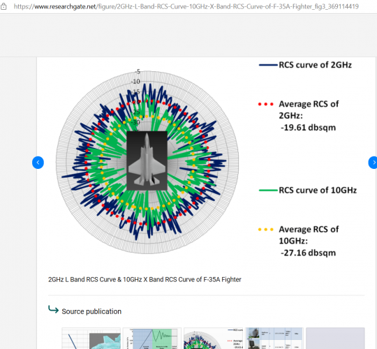
The past existing flat nozzle designs on the F-22 or testbed Su-27 have some crevices that could give high RCS values(the red highlighted parts) which is why I was asking F119Doctor if those deficiencies on existing flat nozzle designs would have higher RCS values than the flat nozzle design of the Su-57. Trying to figure out what he considers as a good or a bad flat nozzle design.
 
The only way to eliminate gaps will be to make them unserviceable, it is just not viable; these things are war machines after all, not luxury items. I figure during a high intensity conflict; stealth skin will not look pristine and mechanics probably wouldn’t have time to make everything neat. On a different note; I have noticed lately the forum has become very heated; let’s try to keep the discussion civil and respectful; there is no need to get angry. We have enough with current geopolitical events to make even this forum a hostile environment.
 
The past existing flat nozzle designs on the F-22 or testbed Su-27 have some crevices that could give high RCS values(the red highlighted parts) which is why I was asking F119Doctor if those deficiencies on existing flat nozzle designs would have higher RCS values than the flat nozzle design of the Su-57. Trying to figure out what he considers as a good or a bad flat nozzle design.
Yes, there are gaps and angles where the F-22 nozzles are not optimum. However, most are either covered by a flexible joint, and/or are coated. The flat sidewalls will reflect, but under most angles the signal will bounce into the AB cavity, which purposely design to swallow RF energy. The position you see the nozzle is the shutdown position, while at most thrust conditions the external flaps are in perfect alignment with the outer mold line. This isn’t true under Max AB or high vector conditions, but LO is probably not the main concerns in this part of a fight.

The flat nozzles and engines shown on the Su-57 have several apparent issues
1. The exposed nozzle sidewalls are not aligned with the vertical fins and airframe sidewalls.
2. The divergent flaps have two angles, neither of which appear to be surface aligned, creating a hexagonal reflecting opening.
3. The internal nozzle sidewalls have a vertically aligned corrugated feature, which would reflect RF energy. It is possible that a smooth liner is not installed on this nozzle in the photo, maybe they haven’t figured out how to cool it properly?
4. The view up back of the engine shows radial flame holders, but there does not appear to be any line of sight blockage for the components forward of the flame holder (spraybars, turbine blades, etc)

LO, especially at the aft end of an afterburning engine, is hard.
 
Why even try to make a LO for the rear of the aircraft if the Doppler effect will be enough
 
Last edited by a moderator:
So, if we are to do a ranking system for rear nozzle stealth it would be something like.

1st place: flat nozzles on the F-22 and Su-70
2nd place: flat nozzles of the Su-57.
3rd place: round nozzles with serrated teeth on the F-35, and what was previously shown for the Su-57 before.
Last place: round nozzles with no serrated teeth which is most 4th gens.
 
On the previous page we have now almost complete translation of the doc. about the Project 'The Scale' that is in connection with the development of the decimetric L band AESA N036L. I forgot that I have some translations of the articles from 2008/2009/2010/2011 about those L band AESA. Here they are:

These are the test results conducted about 20 years ago ( real tests of the L-band AESA prototype antenna in NIIP named after V.V Tikhomirov) .Source is one article of NPP 'Pulsar' from 2008. Mentioned before the model of L-band AESA was first publicly shown on MAKS-2007.


The main problems of creating TRM's for the L-band AESA

''
One of the important components of the L-band AESA is the transmit-receive amplifier module (TRAM), designed to amplify transmitted and received radio pulses.The main problem in creating such a module is the need to implement highly efficient transmission channels with a total output peak power of about 1800 W per four channels with a useful module volume of approximately 2.5 l . In addition to amplifying the input radio pulses to the required level with the required gain, an equally important requirement is the least distortion (deterioration) of the spectral, temporal and noise characteristics of the input radio pulses. The main technical requirements for the receiving and transmitting channels of the PPUM/TRM and the measured characteristics of the model of the TRM are given below in Tables 1 and 2, respectively. The measured values of the characteristics of the breadboard are given for all four channels of the module.


Table 1

Basic technical requirements for the receiving channel of the TRM

Name of parameters : Frequency range, GHz ... Technical requirements : 1.2-1.6 , Measured parameters of the test model : 1.2-1.6
Noise figure, dB ... Technical requirements : 3 , Measured parameters of the test model :1.5-2.3
Transmit coefficient, dB ... Technical requirements : 29-35 , Measured parameters of the test model :36.7-39.3
Unevenness of the transmission coefficient, dB Technical requirements : no more than 2 , Measured parameters of the test model : 0.6-1.3
Gain adjustment depth, dB ...Technical requirements : -15.5 , Measured parameters of the test model : -15.5
Discreet adjustment of the transmit coefficient, dB...Technical requirements :0.5 , Measured parameters of the test model 0.5
VSWR input of the receiving channel ....Technical requirements : no more then 2 ,Measured parameters of the test model : 1.1-1.8

Table 2

Basic technical requirements for the transmitting channel of the TRM

Name of parameters: Output impulse power, W ..Technical requirements : no less than 300 ( for radar mode) and 400-500 ( for IFF mode) ,Measured parameters of the test model : 360-540 ( for radar mode) and 330-480 ( for IFF mode)
Chip of radio pulse, dB..Technical requirements : no more than 0.3 ( for radar mode) and 0.6 ( for IFF mode) ,
Measured parameters of the test model : 0.2-0.7 ( for radar mode) and 0.3-0.5 ( for IFF mode )
The spread of the output power between channels, dB...Technical requirements : no more than 1.0 , Measured parameters of the test model : 1.1 ( for radar mode) and 0.8 ( for IFF mode)
Depth of step electronic output power level control, dB ....Technical requirements :3-5 ( for both modes) ,Measured parameters of the test model : 2.8-4.8 ( for both modes )
The duration of the front of the radio pulse, ns(nanosec).. .Technical requirements : no more than 150 ( for both modes) , Measured parameters of the test model : 100-250 ( for radar mode) and 25-130 ( for IFF mode)
The duration of the falloff of the radio pulse, ns ..Technical requirements : no more than 150 ,Measured parameters of the test model : no more then 30 ( for both modes )
VSWR at the input of the transmitting channel...Technical requirements :no more than 1.5 ,Measured parameters of the test model : 1.2-1.6 ( for both modes)
Efficiency( Duty Cycle ) of transmission channel,% ...no less than 20 , Measured parameters of the test model: 25-32 for the radar mode.
Note: frequency range ΔF2 (radar mode) - τ = 10 μs, Q = 20; frequency range ΔF3 (IFF mode) - τ = 32 μs, Q = 100 .''

It is interesting that Carlo Kopp wrote in his article from 2009 that Duty Cycle is ~20% but several years earlier ,the test model ( prototype of L-band AESA) had 25-32 % of the DC .

From another article ( 2009 ) :

L-band multichannel broadband microwave transmit-receiver module for airborne radar with AESA .

''The modules are 4-channel, each TRM includes a signal processor that controls the amplitude and phase of the TRM , as well as primary information processing. The output power of the TRM is hundreds of W, the capacity of the phase shifters is from 5 to 7 digits, the range the adjustment of the attenuators is about 25 dB.Overall dimensions (HxWxD), no more: 70x1650x90 mm, which are additionally limited by the shape of the available space under the nose fairing .The features of assessing monostatic and bistatic AESA are considered. Numerical algorithms have been tested and a diagram of the backscattering of a phased array from log-periodic and monopole emitters of the decimeter range with an operating frequency range of 1 ... 1.6 GHz is presented when irradiated with a wave of the centimeter range in the band 8.5 ... 12.5 GHz. It is known that the sweep angle of the Su-57 wing is approximately 48°, therefore, to view the radar in the forward direction, it is necessary to deflect the beam at least by the same angle. Max Pulse power per element 500W. Average power per element 250W .The preferred number of elements in the radiating system is 12.''


This is another article about L-band AESA ( also from 2009 );

ON-BOARD LINEAR AESA OF DECIMETRIC BAND

''When placing antennas together decimeter and centimeter wavelengths, a number of problems arise - a largewidth of the radar beam of PESA-AESA for IFF does not allow obtaining a sufficient angular resolution. Moreover, combining emitters of two AESA in a single aperture causes mutual distortion of antenna characteristics. When switching from passive ESA to AESA , difficulties arise in combining two antennas inone aperture. Therefore, the question arises about the possibility of autonomous execution of AESA IFF.In the course of a detailed analysis of the surfaces of modern and future aircraft, it wasrevealed that the most promising is the placement of the AESA IFF in the leading edge of the wing. A rather extended aperture with a length of up to 10λ can be placed in the wing tip, which will be able to provide the required angular resolution in one plane - in azimuth. In practice, this is quite sufficient, despite the lack of angular resolution in the plane elevation angle.In addition, there is the possibility of placing on board not one, but two AESA , which expands the scanning sector of the radar- IFF antenna.

Considering that the constituent AESA blocks have sufficient broadband, AESA can perform the functions of multiple antennas. Considering the positive aspects of placing the IFF antenna in a movable nose wing, do not forget about the strict restrictions on the overall dimensions of the blocks,imposed by such an extraordinary placement. Temperature conditions at variousflight modes and mechanical effects on the blocks create additional difficulties fordevelopers.For example, the temperature in the leading edge of the wing tip can reach + 180°С,and the mechanical loads ( g load) are at least 5.5g. Therefore, special attention waspaid to the development of the emitter, which should form a given DN, taking into account the influence of closely spaced fairing and maintain performance in harsh climatic conditions.Autonomous placement of the IFF antenna assumes a fairly long cable network.

Considering the amount of attenuation in the coaxial conductor, to ensure the requiredenergy parameters, it is necessary to install a powerful transmitter on board. It has becomeone of the reasons for the implementation of the IFF antenna using the AESA technology is the inclusion in the antenna active module.The classic performance of the active modules that make up the AESA assumes monolithic design options. In most cases, it is justified, however, when working in the decimeter wavelength range, the dimensions of the module become rather bulky.Therefore, the AESA IFF is built according to the following scheme: the signal received by the emitting systemamplified in the receiving channel of the module, phase shifters made by a separate device,provide the necessary phase shift in each channel, then the signal from each channelsummed in power dividers. AESA is controlled by the control unitantenna (ACU), the main task of which is the calculation of phase codes and controlphase shifters AESA, i.e. providing electronic scanning with a beam.

All feeding voltages are supplied to the units from a secondary power source.AESA modular design allows compact placement in one wing compartmentactive modules, and in the other - distribution and phasing devices (URF), anddiagram-forming device (DOU). In addition to being compact, such a construction schemeallows you to easily switch from the active version of the antenna to the passive ESA( from AESA to PESA ) , by means of simple exclusion of the amplifier modules from the circuit. All other blocks designed inNIIP are based on proven technologies and can be used for its intended purposein almost any version of the PAR (phased array radar ) . Description of the construction of blocks and their characteristics are given in the full text of the report.The main stages of setting up / working with AESA are:- measurement of the characteristics of active (transceiver) modules;- writing to the flash-memory of control devices (CU) of the necessary correctingdummies allowing to control the amplitude-phase distribution (AFD);- checking the AFD at the output of the amplifier modules as part of the AESA;- mathematical modeling of AESA characteristics using special software forthe results of measurements of the AFD;- measurement of characteristics of radiation AESA.

The measurement of the characteristics of the amplifier modules is carried out in order to compensate for differences between the module channels in phase incursions and the implementation of a given amplitudedistribution. The values of the phase raids of each channel of the module, and the required attenuation value to create a given amplitude distribution( AR ).For this, a four-bit attenuator is installed in the receiving channel of the module, and inthe transmitting channel is provided with a stepwise adjustment of the output power level.The processing of the phases recorded in the CU is carried out by the URF phase shifters.Verification of the accuracy of amplitude-phase distribution-AFD implementation is carried out taking into account the cable network. More details about the verification process are described in the full report. According to the results of measurements of the AFD the expected characteristics of the study of AESA are calculated.At the moment, NIIP has manufactured, configured and tested a sample of AESA-IFF .The sample is made on the basis of an emitting system of 12 emitters combined in three blocks, three 4-channel amplifier modules( TRM), two six-channel distribution and phasing devices and diagram-forming device.The transmission of microwave power between the units is carried out by coaxial cables.''

So this article from 2009 confirms that tests occurred earlier ,in 2008 maybe even earlier as mentioned before and that was in fact model-prototype of L band AESA ( radar and IFF ) for Su-57 in NIIP .This is a very interesting detail :

'' A rather extended aperture with a length of up to 10λ can be placed in the wing tip, which will be able to provide the required angular resolution in one plane - in azimuth. ''

So that kind of antenna could be 240cm in width ( λ=24cm x 10λ ) but instead of that solution ,they made and installed 4 antennas with width of about 160cm in LEVCON's tip and in wing slats tip . There are more technical and tactical possibilities with 4 rather than 2 antennas . As written before, these 4 bigger antennas have two waveguides . One ( upper) for emitting signals when LEVCON's and wing slats are in the lower position and another row ( lower) for emitting signals when LEVCON's and wing slats are in the neutral position.

Advertisement from the MAKS2009

''At the MAKS-2009 air show, at the stand of the Tikhomirov Research Institute of Instrumentation, L-band AESA will also be demonstrated. Designed to fit into the deflectable wing tips of a fighter jet. It is also made on modern hybrid-integral domestic technologies and provides electronic scanning by a beam in a wide sector of angles in azimuth and in a wide frequency band. This locator, like the X-band AESA, was assembled at NIIP, where a unique laboratory testing base was created for this, including anechoic chambers equipped with the latest modern technology.The use of the L-band in air-to-air radar operation is the T-50's primary task of detecting stealth aircraft ''

Then there are some NPP Pulsar articles from 2010/2011 about the modernisation and upgrading of those TRM:

MODERNIZATION OF A POWERFUL L-BAND ON-BOARD AESA MODULE

''The module of the initial development was presented at the Pulsar-2008 conference, and is now being mastered in production. The issue of its modernization is a response to the requirement for a prompt increase in the level of operational characteristics, which is typical of rapidly developing areas of technology.The main goal of the upgrade is to increase the output pulse power level from 400 W to 700 W in a record frequency band of 1 -1.5 GHz in each of the 4 channels of the module. At the same time, the overall and connection characteristics of the module remain unchanged.
The modernization is based on a new generation of integrated assemblies called “power amplifiers” to replace powerful microwave transistors, as well as the development of the principle of volumetric integration.The upgraded module is a transceiver with a noise factor in a given band of no more than 4 dB. A variant of constructive upgrade of the housing is considered in order to improve the technological efficiency of assembly, control and repairability.
In terms of the parameter specific output pulse power per unit of module volume, the obtained result (2 kW/l) exceeds known world achievements.''

ELECTRICAL AND FUNCTIONAL CHARACTERISTICS OF THE UPGRADED MODULE FOR THE L-BAND AIRBORNE AESA

I.V. Korenkov
FSUE NPP Pulsar, Moscow

''The module developed and supplied to the customer is characterized by a high level of output power (400 W per channel), wide bandwidth (1 – 1.5 GHz), and high functional capabilities.The main ones are: high sensitivity in reception mode (noise factor less than 4 dB), the presence of a secondary power source (SPS) with high voltage stabilization rates, multi-level built-in control, ensuring operation in a wide temperature range (from –60°C to +70°C), control of the phase of the received and transmitted signals.During the production and operation of the module, a requirement arose to increase the output power of each channel from 400 to 700 W. At the same time, the customer refused the "antenna equivalent" function.''

All of these info are from the period before test flights with N036L which started from 2013 on the prototype number 055 blue ( 2008-2011). I must find NPP Pulsar articles from 2011/2012 where is mentioned that they increased max output pulse power per channel to almost 1kW.
I am starting to wonder how many 6th gen designs will apply the same concept in making stealth aircrafts hunt other stealth aircrafts.
1743375663196.png
Depending on frequency range of bands and angles the size of RCS returns on radar can be magnified by 10 times the amount. I am assuming most high-end fighter aircrafts have 20 kilowatts max power and performance range of 1m2-3m2 in a 120 degree azimuth search for 200kms and a 1m2-3m2 in a 2 degree beam search for 350-400kms. Even if the L-bands on the Su-57 don't match the main X-band in power the Su-57's own stealth to get a little closer to another adversary stealth aircraft in comparison to 4th gens makes the L-band tracking deadly.

I do hope we get some news on what kind of avionic enhancements the Su-57M has undergone.
 
Show picture of aircraft, then ask for RCS evaluation by eyeballing exterior details.

Fail.

You are talking about me? I’m not the one that stated round nozzles have almost no benefits to flat ones. There are literally multiple scientific sources that did studies on flat nozzles that concluded they have superior IR reduction. I also did post pictures demonstrating how round nozzles have corner reflectors and dozens of discontinuities, gaps, and seams…..I literally posted sources explaining how that increases RCS.

A flat, smooth serrated nozzle will have superior RCS compared to a round none serrated, or even serrated nozzle, due to less moving or stationary parts, gaps, seems. This is the most basic and scientifically proven concept there is.

IMG_2177.png

IMG_2176.png

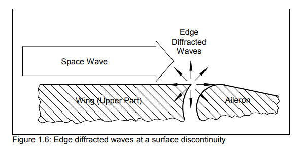
If anyone thinks the round nozzle is anywhere close to a flat nozzle in terms of RCS that is a fail…..look up creeping waves and then try to explain how electromagnetic energy will not be disrupted by dozens discontinuities that serve no purpose for RCS but rather are a consequence of engine back pressure.
 
So, if we are to do a ranking system for rear nozzle stealth it would be something like.

1st place: flat nozzles on the F-22 and Su-70
2nd place: flat nozzles of the Su-57.
3rd place: round nozzles with serrated teeth on the F-35, and what was previously shown for the Su-57 before.
Last place: round nozzles with no serrated teeth which is most 4th gens.
Assumptions with no valid data.
 
You are talking about me?
No, you replied to @flateric
So educate him instead of asking rhetorical questions.
... when he wrote - with which I agreed ...
Your red marks clearly show that you don't understand what "RCS treatment" means.
... in response to @Null here
... posting images and asking ...
So which has better RCS treatment?
... which I would have ignored if there hadn't been numerous instances in this thread alone of people eyeballing images jumping to conclusions. That made me cranky.
 
No, you replied to @flateric

... when he wrote - with which I agreed ...

... in response to @Null here
... posting images and asking ...

... which I would have ignored if there hadn't been numerous instances in this thread alone of people eyeballing images jumping to conclusions. That made me cranky.

What did you agree with? A rhetorical question?

Again those gaps between the F-22 engines and fuselage give off additional RCS no matter how much you deny it. This has been covered to death. Any cavity or discontinuity will cause the RCS to increase. This information is publicly available and has been covered here and by many other publications.

And no just because those gaps have serrations does not mean it will magically cancel out the RCS. The RCS has to go somewhere….The reason why the F-117 doesn’t have as small RCS as an F-22 or B-2 or F-35 is because it used faceting exclusively, where the EM energy was redirected off many different parts of the aircraft. Where as modern stealth aircraft primarily have the EM energy travel along the contours of the aircraft and diffract off fewer areas.

So yes those F-22 gaps definitely…100% increase the RCS just like the SU-57 round engines definitely 100% increase RCS.


And you are cranky at me and quoting me for stating flat nozzles have lower RCS but not cranking at the person claiming flat round nozzles make almost no difference in RCS?
 
Your red marks clearly show that you don't understand what "RCS treatment" means.
This is what I agree with. An opinion, not a question, nor a rhetorical question.

You took this to task:
Plus, the new Su-57 2D flat nozzle just look wrong, and are unlikely to make a large contribution to overall stealth of the aircraft due to adding additional flat surfaces not aligned with the existing airframe edge alignment. It remains to be seen if there will be any significant improvement in observability inside the AB cavity.
I read @F119Doctor comment as directed at the Su-57 2D flat nozzle, not at flat nozzles in general. If I remember correctly, the YF-23's flat nozzles not being vectoring was a deliberate choice by Northrop because of RCS considerations.
 
Last edited:
I am starting to wonder how many 6th gen designs will apply the same concept in making stealth aircrafts hunt other stealth aircrafts.
View attachment 765143
Depending on frequency range of bands and angles the size of RCS returns on radar can be magnified by 10 times the amount. I am assuming most high-end fighter aircrafts have 20 kilowatts max power and performance range of 1m2-3m2 in a 120 degree azimuth search for 200kms and a 1m2-3m2 in a 2 degree beam search for 350-400kms. Even if the L-bands on the Su-57 don't match the main X-band in power the Su-57's own stealth to get a little closer to another adversary stealth aircraft in comparison to 4th gens makes the L-band tracking deadly.

I do hope we get some news on what kind of avionic enhancements the Su-57M has undergone.
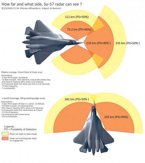
''The greater the wavelength is ,longer is the detecting/tracking distance''. L-Band AESA has 8 times greater wavelength than X- band AESA ( 24cm vs 3 cm).

'Stealthflanker' made some calculations here 5 years ago ( page 39).

N036Estimate-8-13-2020.png

That was in August 2020 but NPP Pulsar made four-channel TRM's with max output pulse power per channel of 700W even 15 years ago. Su-57 of course has 4 linear L-band AESA ( 2 in wingslats and two in LEVCON's) and each 1.6 m wide antenna has in fact 24 radiating elements in the two rows. That is in total,12 RE can be used for the given position of the wingslats/LEVCON's. As mentioned before, L-Band AESA are 2D radars ( tracking by distance-azimuth) where data for elevation can come via data-link from air/ground assets. Again , '' the use of the L-band in air-to-air radar operation is the T-50's primary task of detecting stealth aircraft ''.

I 've found one comment and maybe someone can better explain what it is about...

''WHEN FULLY FUNCTIONAL AND MATURE, THIS L-BAND AESA RADAR HAS THE POTENTIAL TO BE A GAME CHANGER IN AERIAL WARFARE. FIRSTLY IT STANDS A BETTER CHANCE OF DETECTING FIGHTER-SIZED STEALTH AIRCRAFT COMPARED WITH ITS X-BAND COUNTERPARTS AS MOST LOW OBSERVABLE AIRCRAFTS HAVE DESIGNS OPTIMIZED FOR STEALTHINESS IN THE X-BAND. MANY STEALTH SHAPING FEATURES SUCH AS JAGGED EXHAUST NOZZLES, FACETED SURFACES AND SPECIALLY SHAPED ENGINE INLETS BECOME INEFFECTIVE IN THE CONTROLLED SCATTERING OF INCOMING RADAR WAVES WHEN THEIR SIZE APPROXIMATES THE WAVELENGTH OF THE INBOUND PULSE.SO A L-BAND RADAR MIGHT JUST PICK UP A FAINT SIGNATURE WHERE THE X-BAND SEES NOTHING.'
 
@ Null

It is interesting what Carlo Kopp wrote in his article from 2009 about the power of L-band AESA TRM's...

''With the existing Tikhomirov NIIP L-band AESA design using twelve TR channels per array, and a pair of arrays, the NPP Pulsar disclosure permits some estimation of nett AESA power ratings. If we then assume each TR channel can produce one kiloWatt of RF power with more powerful ganged RF transistors with a total rating of 500 Watt / ~20% Duty Cycle, then this yields a rating of 2 x 12 x 1 kiloWatt for a total of 24 kiloWatts for a pair of arrays.''

As we know now in that period ( 2009/2010/2011) ,NPP Pulsar achieved max output pulse power per channel of 700W with the news from 2011/12 that they increased the power to almost 1kW. What Carlo did not count is that Su-57 has four instead of two L-band AESA with a 48 RE's in total for the scanning in one given position of the wingslats/LEVCON's.


Material about RE of the L-band AESA developed under the Project known as 'Horseshoe'.

L-band broadband wide-angle AESA emitters

Problem statement:

The problem of designing emitters of a finite active phased antenna array (AESA) of one type is currently relevant. This AESA is characterized by high energy with wide-angle scanning in a wide frequency band
Objective:

To demonstrate the achievement of an unambiguous mutual understanding by developers and operators of the features of common emitters for the construction of energy-efficient broadband L-band AESAs with wide-angle scanning in two planes.
Results:

The existing technical solutions used in the construction of AESA operating in the decimeter wavelength range are analyzed. The features of the construction of AESA based on symmetric dipoles with a reflector, as well as AESA based on printed emitters are considered in general. An analysis of technical solutions used in the creation of vibrator phased array antennas was carried out, taking into account the requirements for the operating frequency band, ensuring coordination in the required sector of scanning angles, and ensuring the stability of the spatial directivity pattern/radar beam (DP) of the emitters in the array.

Practical significance:

Microstrip emitters and antenna arrays based on them are currently the de facto "standard" in the construction of broadband antennas.However, in the case of constructing highly efficient transceiver arrays in the decimeter frequency range with high pulse powers, the use of dipole-based emitters remains relevant (preferred).
 
''The greater the wavelength is ,longer is the detecting/tracking distance''. L-Band AESA has 8 times greater wavelength than X- band AESA ( 24cm vs 3 cm).
It is not that simple, otherwise all fighters would be using L band or even VHF band as radar.
While it's true that stealth fighters have a larger RCS at lower frequencies, there’s a trade-off. With the same aperture size, the lower the operating frequency, the broader the radar beam becomes. This not only reduces accuracy but also impacts directivity , essentially how focused the energy is. Think of the difference between a flashlight and a laser beam. Lower frequencies wave may travel farther, but that doesn’t necessarily translate to better detection range.
Also, the wider your radar beam is, the more likely that self propelled jammer like MALD-X, SPEAR-EW also located inside your main lobe while you looking at target and you can't use SLC or SLB technique to suppress their signal
 
Last edited:
''The greater the wavelength is ,longer is the detecting/tracking distance''. L-Band AESA has 8 times greater wavelength than X- band AESA ( 24cm vs 3 cm).
Though it must be mentioned that waves traveling further is a double-edged sword - it means that it has to contend with that much more noise and that much easier to jam. A jammers strength decreases with a square of the distance, so if the L-band side array has 200km range, it's possible that a jammer at 1000km can suppress L-band detection - essentially flooding the airwaves and making L-band detection impossible. Which might be why in an actual wartime scenario, where the point is disrupting the enemy killchain, not hiding, that L-band stealth is entirely unnecessary and detection in the same band is impossible.
 
It is not that simple, otherwise all fighters would be using L band or even VHF band as radar.
While it's true that stealth fighters have a larger RCS at lower frequencies, there’s a trade-off. With the same aperture size, the lower the operating frequency, the broader the radar beam becomes. This not only reduces accuracy but also impacts directivity , essentially how focused the energy is. Think of the difference between a flashlight and a laser beam. Lower frequencies wave may travel farther, but that doesn’t necessarily translate to better detection range.
Also, the wider your radar beam is, the more likely that self propelled jammer like MALD-X, SPEAR-EW also located inside your main lobe while you looking at target and you can't use SLC or SLB technique to suppress their signal
L-bands have less accuracy than X-band but are still used for fire control frequencies to track and hit targets from far away, also not counting that electronics for homing heads have improved for further lock on tracking distance capabilities. Is it possible for F-35s or F-22s to jam both L and X-band simultaneously using EW systems or their EW systems can only select one?

Edit: Also very important information I forgot to add. I think generally aircrafts will fly around with a 120-degree radar beam azimuth turned on. Lets say L-band is very useless in tracking to the point that air-to-air missile sensors on the missiles would not find the target if the Su-57s L-band radar pointed at a target from a specific direction. If both aircrafts are stealth and have 1m2 tracking capabilities from 200kms with a 120 degree X-band radar beam and still cannot see each other. The one also using L-band might be able to see the one that is just using X-band and switch its own 120 degree X-band to a 2 degree X-band radar beam to identify where the stealth target is on where the L-band radar found it.

I heard that an F-22 has something like 1m2 target tracking at a 200-240km distance and that it can use a 2 by 2 degree radar beam that would allow it to track the same target 1m2 at 400kms and of course a smaller RCS target than 1m2 can be tracked at 200kms with that same 2 by 2 degree radar beam. If two F-22s have seen each other as adversaries and are 400kms from each other facing in opposite directions, they would still not track each other. But if one got equipped with an L-band radar that F-22 would have a better chance tracking the other F-22 with it and if it is being tracked with that F-22 using L-band that same F-22 can use the 2 degree X-band radar beam to pin point it and track that F-22 1st with better accuracy before that F-22 tracks it back.
If using a 2 by 2 degree X-band radar beam off the bat from a far distance to track a target is like trying to find a needle in a haystack than the L-band can be used as a magnet.
 
Last edited:
L-bands have less accuracy than X-band but are still used for fire control frequencies to track and hit targets from far away, also not counting that electronics for homing heads have improved for further lock on tracking distance capabilities. Is it possible for F-35s or F-22s to jam both L and X-band simultaneously using EW systems or their EW systems can only select one?
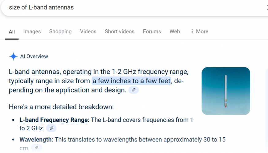
Yes, you can use an L-band radar for fire control, but you'll need a significantly larger antenna. For example, if your X-band radar, operating at a 3 cm wavelength with a 90 cm aperture, has a beamwidth of 2.3 degrees, then to achieve the same beamwidth in L-band (30 cm wavelength), the required antenna diameter would need to be 9 meters.
Yes you can jam both L band and X band at the same times since you can drop multiple decoys. F-35 alone can use APG-81, ALE-70, Brite cloud, Spear-ew or MALD-X to jam.


Edit: Also very important information I forgot to add. I think generally aircrafts will fly around with a 120-degree radar beam azimuth turned on. Lets say L-band is very useless in tracking to the point that air-to-air missile sensors on the missiles would not find the target if the Su-57s L-band radar pointed at a target from a specific direction. If both aircrafts are stealth and have 1m2 tracking capabilities from 200kms with a 120 degree X-band radar beam and still cannot see each other. The one also using L-band might be able to see the one that is just using X-band and switch its own 120 degree X-band to a 2 degree X-band radar beam to identify where the stealth target is on where the L-band radar found it.

I heard that an F-22 has something like 1m2 target tracking at a 200-240km distance and that it can use a 2 by 2 degree radar beam that would allow it to track the same target 1m2 at 400kms and of course a smaller RCS target than 1m2 can be tracked at 200kms with that same 2 by 2 degree radar beam. If two F-22s have seen each other as adversaries and are 400kms from each other facing in opposite directions, they would still not track each other. But if one got equipped with an L-band radar that F-22 would have a better chance tracking the other F-22 with it and if it is being tracked with that F-22 using L-band that same F-22 can use the 2 degree X-band radar beam to pin point it and track that F-22 1st with better accuracy before that F-22 tracks it back.
If using a 2 by 2 degree X-band radar beam off the bat from a far distance to track a target is like trying to find a needle in a haystack than the L-band can be used as a magnet.
This is a common misconception about how radar works. A radar’s beamwidth is determined by its operating frequency and aperture size higher frequencies or larger apertures result in a narrower beam.
When a radar manufacturer states that a system has a 200 km range with a 120-degree search volume and a 400 km range with cued search, What they actually mean is that you when you reduce radar search volume, your dwell time at each beam position will increase. And that result in longer detection range because you integrate higher number of pulses together.
Yes, you can use an L-band radar to reduce the search volume of an X-band radar, effectively increasing X-band radar detection range. However, the reverse is also true. When operating any radar whether L-band or X-band you expose yourself to enemy ESM. And if they have sensor fusion, that ESM will also cue their radar toward your direction
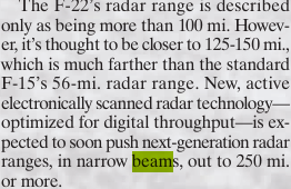
 
L-bands have less accuracy than X-band but are still used for fire control frequencies to track and hit targets from far away
Yeah but now you're talking about a radar much much larger than whatever the su57 can carry. This mythical "radar" function of the L-band arrays are more myth than physics. Be aware of some of these russian sources being just magazines, sites, and blogs much like the american TWZ.com rather than actual manufacturers' claims. And even then, it's not like russian manufacturers are not well known for lofty claims that are not backed with performances in the real world.
 
Last edited:
And if they have sensor fusion, that ESM will also cue their radar toward your direction
Which is true, but L band emitter gets whole 255 deg picture in a faster scan; silent or no. Both can do frequency hopping(LPI) to complicate things, and shooting down su-57 is in any case massively more difficult than shooting down AWACS.

Opfor cues only on the emitter; rest of redfor maintains privilege of keeping silence.
This is a significant synergy with GBAD(and unified fuzed air situation), other felons(bystatics), and especially other redfor fighters (cued narrow search and engagement).

There is merit to aggressiveness, if one can survive it. If you're fighting a much larger LO force with inferior non-LO force, this is unavoidable risk, If you want to guarantee bluefor will be seen and engaged.
If you can live without it - no problem, but you'll end up as Iran, North Korea or Ukraine: spicy, but leaky. Saddam has shown potential consequences.

GBADs, normal fighters under ground control and AWACS will only get you so far; LO force will eventually disassemble them simply through superiority in initiative.

Otherwise, the only real option to provide robust defense is to aim at >1:1 force without discarding gbad. That's Soviet Union/China.
 
Last edited:
So *checks notes* for the next 35 years, that is? Even less, if we consider that Russian equipment are usually cheaper because they have less usable life built into them...

So, in short, sensor fusion and MUM-T? That hardly makes the Su-57 a 6th-gen fighter—at most, it's a 5.5th-gen.

And if we consider that broadband-VLO is typically considered a critical design element of what makes a jet '6th gen,' this is another aspect where the Felon falls short compared to its competitors...
It was stated to include technologies which are generally associated with the "sixth generation".

One such technology being the effective use of UCAV "wingmen" or as the Americans call them CCA (collaborative combat aircraft). Something the Su-57 more or less pioneered within it's generation through tests with the S-70 UCAV years ago.

It's pretty evident, especially considering joint testing under combat conditions behind enemy lines in UA, that the Russians are very committed to get the S-70 worked out and to get it to work in conjunction with the Su-57.

On top of that comes the patent for the tandem seat Su-57 (Su-57D? Su-60?) which was labeled something along the lines of battlefield management complex, I can remember something like that. So similar to the J-20S it will be tandem seat stealth fighter that's intended to make use of CCAs to boost it's combat effectiveness and extend the sensor and strike range beyond what the actual jet usually is able to achieve. And just like the J-20S which is based on the J-20A, the Su-57D/Su-60 will be based on the Su-57M.

So you have a modernized 5th generation fighter that can operate with combat drones and has the necessary hard and software to do so effectively. In short, you have a modernized 5th Gen that can do something that's heavily associated with the next generation of jet fighters.

So yeah, as they said, it will feature some aspects of next generation developments. Or as you said "5.5th Gen".
 
I always thought that The Su-47 was so cool, much in the same manner as The YF-23 was radically different to what eventually became The F-22, & unlike The Su-57, The Berkut also had proper S-Ducts but only one weapons bay. I could also see them modifying the design to change the shape of the intakes & add levcons later down the road, but ultimately, one of the primary reasons that it was never adopted was due to the problems with forward-swept wings limiting the maximum speed to Mach 1.6, which, ironically enough, is currently the same limit as The F-35, albeit for reasons related to RAM, iirc.

Never forget, however, that The Su-47 first flew at a time when Russia was still in the abject misery of The 1990s, so the money simply wasn't there, even if it could have been built in numbers, so in the end, the platform wound up being a kind of flying laboratory for various technologies that were later incorporated into The Su-57, so it wasn't a total loss. I can't do anything about the irst bulb, though, lol, smh.

As for The Su-75, yes, it's a much better stealth design, especially if they opt to keep the v-tail, & The Checkmate also features a faceted EOTS-like device underneath the fuselage, so it looks like someone at Sukhoi finally got the memo in that regard, but evidently, everyone is STILL not on the same page as the aircraft retains the standard irst bulb in front of the cockpit. Sigh.

In terms of modifying The Su-57, it would probably be best to get rid of the second weapons bay so as to ease the overall stress on the airframe & then smooth the bottom, which would also yield more storage for the single weapons bay. Do that, give us a faceted irst, said EOT-like setup from The Su-75, & then let's see where we are in terms of its rcs. Who knows - a return of 0.006 m2, or thereabouts, might actually be quite attainable, provided that the dircms are also removed. Continuing down the current road is just a waste of time & money, imo.

Oops, almost forgot - the partial S-Ducts are also complex, expensive, & don't yield the necessary level of radar reduction, so yeah. Not great, Bob.

So your prospect to make the aircraft "better" is crippling it's ability to carry ordnance (removing an entire weapons bay, literally one of the driving factors of the entire design) as well as making it less survivable (removal of DIRCM)?

At that point just say you think the MiG-15 is optimal aircraft, given it lacks such "flaws", and should be produced again in the thousands.

Who needs a supercruising stealth fighter that can carry several Kh-69s internally and has direct infrared countermeasures to stay alive longer? Clearly all these engineers at sukhoi with their diplomas have no idea how an aircraft is designed after several decades of doing it. Luckily you enlightened us all.
 
This is a common misconception about how radar works. A radar’s beamwidth is determined by its operating frequency and aperture size higher frequencies or larger apertures result in a narrower beam.
When a radar manufacturer states that a system has a 200 km range with a 120-degree search volume and a 400 km range with cued search, What they actually mean is that you when you reduce radar search volume, your dwell time at each beam position will increase. And that result in longer detection range because you integrate higher number of pulses together.
Yes, you can use an L-band radar to reduce the search volume of an X-band radar, effectively increasing X-band radar detection range. However, the reverse is also true. When operating any radar whether L-band or X-band you expose yourself to enemy ESM. And if they have sensor fusion, that ESM will also cue their radar toward your direction

1743523238499.png
Any turned on radar in general get exposed to ESM, it's not like most aircrafts in combat will use RWR and infrared as the main source to track targets. Unless you're telling me that RWRs are sufficient enough to cue any aircrafts radar beam to be narrower to point towards the target where the RWR will show where it's at?


Yes, you can use an L-band radar for fire control, but you'll need a significantly larger antenna. For example, if your X-band radar, operating at a 3 cm wavelength with a 90 cm aperture, has a beamwidth of 2.3 degrees, then to achieve the same beamwidth in L-band (30 cm wavelength), the required antenna diameter would need to be 9 meters.
Yes you can jam both L band and X band at the same times since you can drop multiple decoys. F-35 alone can use APG-81, ALE-70, Brite cloud, Spear-ew or MALD-X to jam.
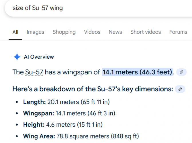
Yeah but now you're talking about a radar much much larger than whatever the su57 can carry. This mythical "radar" function of the L-band arrays are more myth than physics. Be aware of some of these russian sources being just magazines, sites, and blogs much like the american TWZ.com rather than actual manufacturers' claims. And even then, it's not like russian manufacturers are not well known for lofty claims that are not backed with performances in the real world.

1743523664862.png
1743523900009.png
 

Please donate to support the forum.

Back
Top Bottom