Su-57 Avionics

stealthflanker

ACCESS: Top Secret
Senior Member
Joined
11 February 2010
Messages
1,636
Reaction score
2,644
Thank you for all the data.What is the main problem for us ('public') is that we don't know real characteristics of those TRMs inside of the four centimetric X-band AESA.


Then what ? You can use that paper and do your own calculation. Especially that Radar Range Equation is widely known and all you need is some reasonable basic assumption.

14-18 Watt use that.

Just dumping articles and papers without actually draw meaningful information is kinda like spamming tbh.
 
@Ronny

Yes, tnx. I've found some data :

Pulse Doppler radars remain the primary long range sensors used by fighter aircraft for BVR combat.Peak Power (Ppeak) [kW] is the maximum pulsed power the radar can emit.


So what we have ... 1526 TRM's in the main forward N036 AESA x 10W =15.26 kW + 2 SLAR N036B AESA with 358 TRM's each is 716 x 10W=7.16 kW ,total= 22.42 kW ?
I can't see a reason to add up the peak power output of three non-overlapping antennas.

The interesting comparison would be the ratio of power to the side arrays compared to front - basically only a quarter, so all things equal max detection range for these is similarly less.
 
Then what ? You can use that paper and do your own calculation. Especially that Radar Range Equation is widely known and all you need is some reasonable basic assumption.

14-18 Watt use that.

Just dumping articles and papers without actually draw meaningful information is kinda like spamming tbh.

Theory and papyrology,yes....

In contrary, if I may, I will present two cases from the practice ,real life.

On March 1999 during Operation Allied Force, one YuAF MiG-29B pilot, detected and tracked low-flying cruise missile (it was BGM-109 Tomahawk) at a distance of 30km in the front hemisphere. If I am right ,BGM-109 with metallic skin has about 0.3 sqm of frontal RCS in centimetric X-band ( angle aspect +/-15°) ? He flew at about 4000m ,cruise missile at about 100m AGL. Radar N019EB of his MiG-29B could not work in the lock-on mode. As we know,N019EB was downgraded export version of the N019 for non-WP countries.Radar N019 'Rubin' possess TWT with about 1kW of average power in the HPRF mode and with max output pulse power of about 8kW in HPRF mode. Due to unfinished overhaul during 1996/97, the YuAF MiG-29Bs had mostly malfunctioning radars with significantly weakened TWT's.

On May 2013, during the exercise over Pemboi range in Syberia ,one MiG-31DZ locked-on and engage incoming low-flying cruise missile Kh-55 launched from the Tu-95MS with AAM type R-33 from a distance of 90km. Detection/tracking distance was certainly bigger. N007 Zaslon's main TWT has 2.5kW of average power in HPRF mode and has max output pulse power of 10kW in HPRF mode. PRF in the HPRF mode for both is 180-200kHz.

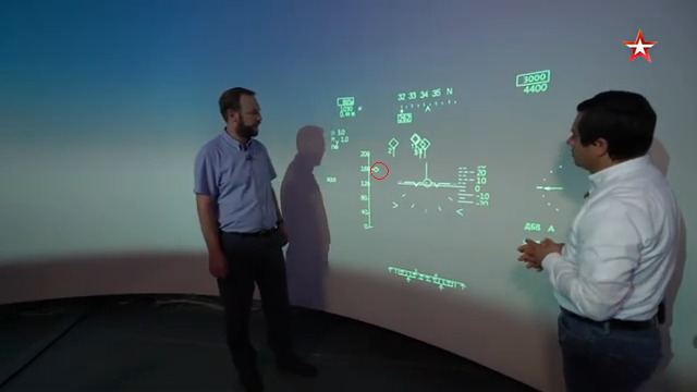
If we talk about N036 ( frontal AESA) maybe only that we have are some sequences made in 2018 in Sukhoi sim-room. From 21:42 we can see 4 aircraft tracked in PPS mode ( front hemipshere) with a current distance to aircraft scale.Numbers besides scale are : 40,80,120,160 and 200 km.Suppose that it was half of the main scale ranging from 0-400km (0-50-100-150-200-250-300-350-400 , like for N035 Irbis).

View: https://www.youtube.com/watch?v=FsXUJYEp0B4
 
Last edited:
Theory and papyrology,yes....

Any radar design regardless origins of country start with Radar range equation. whether you like it or not. Differences with practical experience lies in the manufacturing and then environment. Good book exist and this one below is actually translated from Russia on the subject.

1742510474108.png


If we talk about N036 ( frontal AESA) maybe only that we have are some sequences made in 2018 in Sukhoi sim-room. From 21:42 we can see 4 aircraft tracked in PPS mode ( front hemipshere) with a current distance to aircraft scale.Numbers besides scale are : 40,80,120,160 and 200 km.Suppose that it was half of the main scale ranging from 0-400km (0-50-100-150-200-250-300-350-400 , like for N035 Irbis).

Yeah and they're at 180 km range, if that arrow i circled in red indicates the distance.
1742510294287.png

It doesnt however really tell anything about TRM ratings. It only tell several targets are being detected at x range.

In contrary, if I may, I will present two cases from the practice ,real life.

On March 1999 during Operation Allied Force, one YuAF MiG-29B pilot, detected and tracked low-flying cruise missile (it was BGM-109 Tomahawk) at a distance of 30km in the front hemisphere. If I am right ,BGM-109 with metallic skin has about 0.3 sqm of frontal RCS in centimetric X-band ( angle aspect +/-15°) ? He flew at about 4000m ,cruise missile at about 100m AGL. Radar N019EB of his MiG-29B could not work in the lock-on mode. As we know,N019EB was downgraded export version of the N019 for non-WP countries.Radar N019 'Rubin' possess TWT with about 1kW of average power in the HPRF mode and with max output pulse power of about 8kW in HPRF mode. Due to unfinished overhaul during 1996/97, the YuAF MiG-29Bs had mostly malfunctioning radars with significantly weakened TWT's.

On May 2013, during the exercise over Pemboi range in Syberia ,one MiG-31DZ locked-on and engage incoming low-flying cruise missile Kh-55 launched from the Tu-95MS with AAM type R-33 from a distance of 90km. Detection/tracking distance was certainly bigger. N007 Zaslon's main TWT has 2.5kW of average power in HPRF mode and has max output pulse power of 10kW in HPRF mode. PRF in the HPRF mode for both is 180-200kHz.

Then what's the point ?
 
Any radar design regardless origins of country start with Radar range equation. whether you like it or not. Differences with practical experience lies in the manufacturing and then environment. Good book exist and this one below is actually translated from Russia on the subject.

View attachment 763677


Yeah and they're at 180 km range, if that arrow i circled in red indicates the distance.
View attachment 763670

It doesnt however really tell anything about TRM ratings. It only tell several targets are being detected at x range.


Then what's the point ?

Of course,as mentioned before ,first comes theory,papyrology,math. modelling,comp. simulation etc... Thanks for the recommended book.

160 km exactly ,arrow show that current distance to aircraft/target ,yes.

No of course but the point of the story is that we have sometimes completely different data ,values etc in the practice then what we can read from some sources.

In the meantime....

Yury Trutnev (as Deputy Prime Minister of Russia and Presidential Envoy to the Far Eastern Federal District) was in KnAAZ about month ago. We can see one almost finished new Su-57.Maybe it is already finished and ready for the delivery...

View: https://www.youtube.com/watch?v=azoBMiXJrZs
 
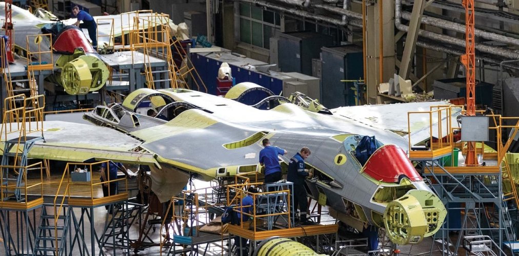
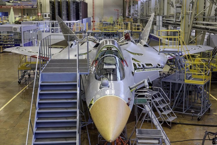
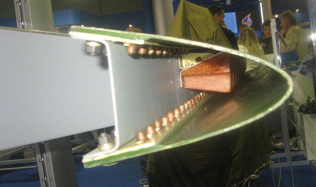
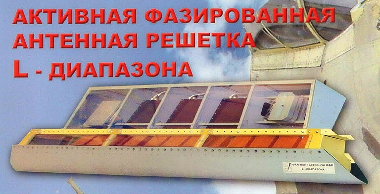
We mentioned and wrote some comments about that decimetric L-band AESA radars N036L.Here we can see them during serial production of the Su-57's in the KnAAZ.

Su-57 in KnAAZ 1.jpg

Su-57 in KnAAZ.jpg

In the meantime I've finally found some transl. of those pages that we have from the Russian doc. If I may, I will put it them here.Page 1 is already translated .

''2. Goals, objectives and initial data for the work 2.1 Goal of the work Development of technology, algorithms and hardware for assessing and adjusting the amplitude-phase characteristics and directional diagrams of the PESA and AESA and their elements during the creation and serial production of the radar. 2.2 Objectives of work In the course of the R&D, the following tasks should be solved: - a basic technology for creating a linear phased array (PESA) / AESA of the L-band and a general scheme for its construction, ensuring the implementation of the modes of operation of the IFF and radar; - the basic technologies for the manufacture of key devices AESA-L have been developed:a block of emitters, a receiving-transmitting amplifier module ( TRM or PPUM), a distribution and phasing device (URF) and a pattern generator ( radar beam ) ; - prototypes of input devices for linear PESA / AESA L-band were developed and manufactured in accordance with the general construction scheme; - programs and methods were developed, and prototypes of input devices of linear PESA / AESA L-band were adjusted and tested; -tests of the created technology, algorithms and hardware for assessing and adjusting the amplitude-phase characteristics and directional patterns ( radiation patterns -radar beams) of the PESA and AESA and their elements were carried out. - a set of letter complect ( Liter on russian for adjusting working frequencies or radiation patterns ) type "O" was developed for prototypes of the L-band PESA / AESA input devices and test models for the developed technologies; - the conclusion of the consumer enterprise was received on the level of parameters provided by the developed technology; - proposals were given for the manufacturer, the procedure and terms for mastering the product. 2.3 Initial data .As a result of the R&D, basic technologies should be created for the production of key input devices of the L-band PESA / AESA, taking into account the possibility of placement on the T-50 , consisting of: specified radiation characteristics when working with a specialized radio-transparent fairing; - the distribution and phasing device should be based on the microwave hybrid-integral Circuits for SHF ( Super High Frequency ) with hinged mounting of LF ( Low Frequency) control components and the use of a microstrip transmission line; - the radiation pattern ( radar beam ) former should be made on the basis of a symmetrical strip line, using modern materials such as Rodgers ( Rodgers materials ) ; - TRM should be made four-channel, with power amplifiers (PA) for transmission and reception in each of them. All PAs are based on microwave /Monolithic Integrated Circuits for SHF with the implementation of low duty cycle (Q = 20) modes, provided when using liquid cooling.''

''3. The electrical circuit of the TRM must ensure interface with the mains of control and information signals. Stage 3. Content of work 3.1 Stages of work and their results Content of work of stage Result 1 Draft and technical design for technologies, algorithms and hardware for assessing and adjusting the amplitude-phase characteristics and directional diagrams of the phased array/PESA and AESA and their elements during the creation and serial production of the radar ... Development of the basic technology for constructing PESA / AESA L-band. Development of basic technologies for the manufacture of key PESA / AESA devices for the emitter unit, TRM, URF ( distribution and phasing devices) , pattern generator. Manufacturing of models of L-band AESA input devices. (what is presented) Explanatory note to the draft technical design on technologies, algorithms and hardware for assessing and adjusting the amplitude-phase characteristics and directional patterns of the phased array/PESA and AESA and their elements during the creation and serial production of the radar ..Models of the input devices of the phased array / AESA L-band : -- block of emitters; - transceiver amplifier module; - distribution and phasing device; - radiation pattern /beam shaper. Terms of implementation Terms of performance of stages of work are set at the conclusion of a state contract 2 Development of design documentation for prototypes of input devices of the L-band phased array -PESA/AESA and techn. doc. for the developed technologies. Development of programs and test methods for models of input devices for linear PESA / AESA L-band. Testing of models of input devices of L-band phased array-PESA / AESA. Design documentation for prototypes of L-band phased array / AFAR input devices and technical documentation for developed technologies. The program and methods of testing the models of the input devices of the L-band PESA / AESA. Test reports of the models of the incoming The deadlines for the stages of work are established at the conclusion of the state contract.''

''4. Stage Content of stage work Result 3 Manufacturing of prototypes of L-band phased array -PESA/ AESA input devices. Conducting preliminary tests of prototypes of the input devices of the L-band PESA / AESA . Adjustment of design documentation and technical documentation based on PI results. Assignment of the letter "O" ( working frequencies) to RKD, TD ( static and flight test models ) Methodology for predicting the characteristics of L-band PESA / AESA based on the test results of prototypes of input devices. (what is shown) devices. Acts and protocols of PI of prototypes of input phased array / PESA and AESA L-band devices. Sets of test models letter "O" for prototypes of the input devices PESA / AESA L and TD of the letter "O" for the developed technologies. Scientific and technical report on ROC. Terms of performance Terms of performance of stages of work are established when concluding a state contract Note: 1. The content of stages of work is specified according to the results of a competition when concluding a state contract. 2. The list of documents developed during the organization and implementation of R&D (R&D stages) are presented in accordance with the requirements of GOST RV.( GOST RV 15.002-2003 “System of product development and launching into production. Military equipment. Quality Management System. General Requirements "is a state military standard of the Russian Federation that sets requirements for a quality management system. ) 1. Sets of CD letter "O" for prototypes of input devices L-band PESA / AESA and TD letter "O" for the developed technologies. 2. Models of the incoming PESA / AESA L-band devices. 3. Prototypes of L-band phased array PESA / AESA input devices including: - block of emitters; - transceiver amplifier module ( TRM or PPUM);''

''6. - Distribution and phasing device (URF) - DN shaper ( radar beam ) . 4.2 Requirements for the designation of the L-rband phased array PESA / AESA as part of the developed prototypes of input devices is intended for directional transmission of radar signals and signals of the state identification system in the frequency range GHz (f1 subband) and GHz (f2 subband), respectively, as well as for receiving signals in the frequency band GHz Linear L-band PESA / AESA as part of the developed prototypes of input devices should provide one-dimensional electronic beam control in all specified frequency ranges in the azimuthal angular sector of the L-band PESA / AESA should form the following radar beam pattern. When operating in the f1 sub-band: - total DN ( radiation pattern) during transmission and reception; - differential DN during reception (simultaneously with the total); - compensatory beam when working at the reception (simultaneously with the total);When operating in the f2 sub-band: - total DP during transmission and reception; - compensatory DN during transmission; - compensatory DN when working at the reception (simultaneously with the total); When working on transmission, it should be possible to form a total DN for two operating modes of the maximum power mode and optimal DN. Scanning sector of AESA L -band in the azimuthal plane is +/-55°. The appearance of diffraction lobes when scanning in a given sector is not allowed. The polarization of the field of the emitted and received signals is vertical. The potential for transmitting in the maximum power mode should be at least ( no less then ) 360X n2 Watts, where n is the number of emitters ( 12 pour one antenna ) . The potential for transmitting in the optimal DN ( radar beam ) mode should be at least 250X n2 Watts , where n is the number of emitters. The gain in the receive mode must be at least 7X n2, where n is the number of emitters. The width of the radiation pattern/ beam in the azimuthal plane at a level of minus 3 dB when operating in the f1 sub-band should be.''

''7. When operating in transmission : - maximum power mode, degrees - (130+ - 3) / N / cosΘ; - optimal DN mode, deg - (125+ - 3) / N / cosΘ where Θ is the angle of deviation of the main maximum of the DN relative to the normal to the antenna, N is the number of emitters . When operating on receiving , deg: (135+ - 3) / N / cosΘ, where Θ is the deflection angle the main maximum of the pattern relative to the normal to the antenna, N number of emitters; optimal DN mode, deg - (108+ - 2) / N / cosΘ; where Θ is the angle of deviation of the main maximum of the antenna pattern relative to the normal to the antenna, N is the number of emitters When operating at reception, degrees: (120+ - 2) / N / cosΘ, where Θ is the angle of deviation of the main maximum of the pattern relative to the normal to the antenna, N is the number of emitters. Width of the pattern in the elevation plane at the level of minus 3 dB should be 70-90 degrees in all modes. When operating in the f1 subband, the maximum side lobe of the total DN should be in the + - 30 / cosθ zone relative to the beam axis.The level of the maximum side lobe at the axial position of the beam should not be higher than minus 17 dB in the transmission mode and minus 22 dB in the receiving mode. - The overlap ratio of the side lobes of the total DP of the differential DP when transmitting in the f2 subband must be at least: For the maximum range mode: - in the scanning sector to; + - 30° -0.68 - in the scanning sector over; + - 25° -0.62. For the optimal DN mode: in the scanning sector up to; + - 25° -0.78 - in the scanning sector above the + - 25° -0.70 . Coefficient of overlapping of the side lobes of the total DN of the differential DN when working for receiving in the f2 subband must be at least: - in the scanning sector to; + - 25° -0.86 - in the scanning sector above the + - 25° -0.80 . Depth of the difference DN minimum relative to the total DN maximum should be at least 25 dB . The steepness of the synthesized direction finding characteristic (DF) should be at least 15cosΘ% / deg. Beam positioning error no more than:''

''8. when working in the sub-range ∆f1: 0.8 ° / cosΘ; - when working in the sub-range ∆f2: 0.6 ° / cosΘ The installation time of the L-band PESA / AESA beam in any angular position should not exceed 10 μs. The DN inversion time should not exceed 0.4 μs. The return to the initial antenna pattern should be made no more than 0.4 μs after the control signal is applied. Requirements for the characteristics of the emitter unit . The standing wave ratio level or VSWR at the emitter input must not exceed the 1.8 . Emitters must have linear polarization orthogonal to the AESA plane . The mass of the emitter unit must not exceed 0.87 kg . Requirements for characteristics of PPUM-TRM PPUM should have 4/5 transmitting / receiving channels . The output pulse power per channel should be at least 400 W. The maximum deviation of the output power value should be no more than 50 W. Parameters of the amplified pulse: - duration, 1-100μs; - duty cycle;20-200Requirements for the shape of the output pulse in the f1 subband : - duration of the rise and fall, no more, 0.1μs: narrowing of the envelope relative to the input pulse, no more,0.1 μs: front delay relative to the input pulse, no more, 0.1 μs . - bevel of the top of the envelope, no more, 2% Requirements for the shape of the output pulse in the f2 subband: - duration of the leading edge, no more, 0.15μs: - duration of the fall, no more than, 0.25μs: The noise figure of the receiving channel should not exceed 3dB , The efficiency of the TRM must be at least 20%.Power consumption of TRM should not exceed 500W , The mass of the TRM should not exceed 4.35 kg Requirements for distribution and phasing device , must be four-channel.''

''9. Distribution and phasing device (URF) should form a constant amplitude distribution at the outputs in the case of an active PA/AESA and uneven according to a special law in the case of a passive PA/PESA . The bit width of the phase shifter is not less than 5. The standard deviation of the phase setting at the URF outputs should not exceed 5° , URF must have an efficiency of at least 60%. Power consumption should not exceed 19 W. The mass of the URF should not exceed 0.42 kg. Requirements for the DN/beam generator The VSWR level at the inputs and outputs of the DN generator should not exceed 1.3.. The transmission coefficient from the input to the outputs of the antenna pattern shaper should be 3.2 ± 0.3 dB. The decoupling between the outputs of the antenna pattern must be at least 27 dB .. The DN mass former should not exceed 0.13 kg.Increased temperature of the environment for prototypes of the input devices of the PESA / AESA L-band, placed in the front part of the deflected toe of the wing: -working, ° С - plus 75 °; -working increased short-term, ° С - plus 135 °; -limiting, ° С - plus 140 ° . Reliability requirements. Criteria for failure of prototypes of input PESA / AESA L-band devices should be determined at the development stage .So that's it ,pages 10,11 and 12 give some info that are not more interesting ( no techn. data ) .''

Oooops, hm I obviously lost page no 5, sorry.
 
On the previous page we have now almost complete translation of the doc. about the Project 'The Scale' that is in connection with the development of the decimetric L band AESA N036L. I forgot that I have some translations of the articles from 2008/2009/2010/2011 about those L band AESA. Here they are:

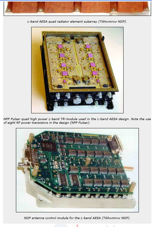
These are the test results conducted about 20 years ago ( real tests of the L-band AESA prototype antenna in NIIP named after V.V Tikhomirov) .Source is one article of NPP 'Pulsar' from 2008. Mentioned before the model of L-band AESA was first publicly shown on MAKS-2007.


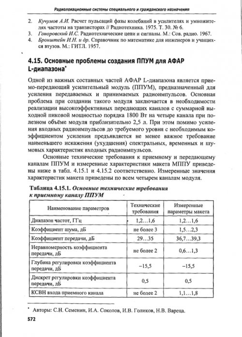
The main problems of creating TRM's for the L-band AESA

''
One of the important components of the L-band AESA is the transmit-receive amplifier module (TRAM), designed to amplify transmitted and received radio pulses.The main problem in creating such a module is the need to implement highly efficient transmission channels with a total output peak power of about 1800 W per four channels with a useful module volume of approximately 2.5 l . In addition to amplifying the input radio pulses to the required level with the required gain, an equally important requirement is the least distortion (deterioration) of the spectral, temporal and noise characteristics of the input radio pulses. The main technical requirements for the receiving and transmitting channels of the PPUM/TRM and the measured characteristics of the model of the TRM are given below in Tables 1 and 2, respectively. The measured values of the characteristics of the breadboard are given for all four channels of the module.


Table 1

Basic technical requirements for the receiving channel of the TRM

Name of parameters : Frequency range, GHz ... Technical requirements : 1.2-1.6 , Measured parameters of the test model : 1.2-1.6
Noise figure, dB ... Technical requirements : 3 , Measured parameters of the test model :1.5-2.3
Transmit coefficient, dB ... Technical requirements : 29-35 , Measured parameters of the test model :36.7-39.3
Unevenness of the transmission coefficient, dB Technical requirements : no more than 2 , Measured parameters of the test model : 0.6-1.3
Gain adjustment depth, dB ...Technical requirements : -15.5 , Measured parameters of the test model : -15.5
Discreet adjustment of the transmit coefficient, dB...Technical requirements :0.5 , Measured parameters of the test model 0.5
VSWR input of the receiving channel ....Technical requirements : no more then 2 ,Measured parameters of the test model : 1.1-1.8

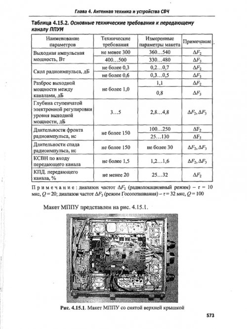
Table 2

Basic technical requirements for the transmitting channel of the TRM

Name of parameters: Output impulse power, W ..Technical requirements : no less than 300 ( for radar mode) and 400-500 ( for IFF mode) ,Measured parameters of the test model : 360-540 ( for radar mode) and 330-480 ( for IFF mode)
Chip of radio pulse, dB..Technical requirements : no more than 0.3 ( for radar mode) and 0.6 ( for IFF mode) ,
Measured parameters of the test model : 0.2-0.7 ( for radar mode) and 0.3-0.5 ( for IFF mode )
The spread of the output power between channels, dB...Technical requirements : no more than 1.0 , Measured parameters of the test model : 1.1 ( for radar mode) and 0.8 ( for IFF mode)
Depth of step electronic output power level control, dB ....Technical requirements :3-5 ( for both modes) ,Measured parameters of the test model : 2.8-4.8 ( for both modes )
The duration of the front of the radio pulse, ns(nanosec).. .Technical requirements : no more than 150 ( for both modes) , Measured parameters of the test model : 100-250 ( for radar mode) and 25-130 ( for IFF mode)
The duration of the falloff of the radio pulse, ns ..Technical requirements : no more than 150 ,Measured parameters of the test model : no more then 30 ( for both modes )
VSWR at the input of the transmitting channel...Technical requirements :no more than 1.5 ,Measured parameters of the test model : 1.2-1.6 ( for both modes)
Efficiency( Duty Cycle ) of transmission channel,% ...no less than 20 , Measured parameters of the test model: 25-32 for the radar mode.
Note: frequency range ΔF2 (radar mode) - τ = 10 μs, Q = 20; frequency range ΔF3 (IFF mode) - τ = 32 μs, Q = 100 .''

It is interesting that Carlo Kopp wrote in his article from 2009 that Duty Cycle is ~20% but several years earlier ,the test model ( prototype of L-band AESA) had 25-32 % of the DC .

From another article ( 2009 ) :

L-band multichannel broadband microwave transmit-receiver module for airborne radar with AESA .

''The modules are 4-channel, each TRM includes a signal processor that controls the amplitude and phase of the TRM , as well as primary information processing. The output power of the TRM is hundreds of W, the capacity of the phase shifters is from 5 to 7 digits, the range the adjustment of the attenuators is about 25 dB.Overall dimensions (HxWxD), no more: 70x1650x90 mm, which are additionally limited by the shape of the available space under the nose fairing .The features of assessing monostatic and bistatic AESA are considered. Numerical algorithms have been tested and a diagram of the backscattering of a phased array from log-periodic and monopole emitters of the decimeter range with an operating frequency range of 1 ... 1.6 GHz is presented when irradiated with a wave of the centimeter range in the band 8.5 ... 12.5 GHz. It is known that the sweep angle of the Su-57 wing is approximately 48°, therefore, to view the radar in the forward direction, it is necessary to deflect the beam at least by the same angle. Max Pulse power per element 500W. Average power per element 250W .The preferred number of elements in the radiating system is 12.''


This is another article about L-band AESA ( also from 2009 );

ON-BOARD LINEAR AESA OF DECIMETRIC BAND

''When placing antennas together decimeter and centimeter wavelengths, a number of problems arise - a largewidth of the radar beam of PESA-AESA for IFF does not allow obtaining a sufficient angular resolution. Moreover, combining emitters of two AESA in a single aperture causes mutual distortion of antenna characteristics. When switching from passive ESA to AESA , difficulties arise in combining two antennas inone aperture. Therefore, the question arises about the possibility of autonomous execution of AESA IFF.In the course of a detailed analysis of the surfaces of modern and future aircraft, it wasrevealed that the most promising is the placement of the AESA IFF in the leading edge of the wing. A rather extended aperture with a length of up to 10λ can be placed in the wing tip, which will be able to provide the required angular resolution in one plane - in azimuth. In practice, this is quite sufficient, despite the lack of angular resolution in the plane elevation angle.In addition, there is the possibility of placing on board not one, but two AESA , which expands the scanning sector of the radar- IFF antenna.

Considering that the constituent AESA blocks have sufficient broadband, AESA can perform the functions of multiple antennas. Considering the positive aspects of placing the IFF antenna in a movable nose wing, do not forget about the strict restrictions on the overall dimensions of the blocks,imposed by such an extraordinary placement. Temperature conditions at variousflight modes and mechanical effects on the blocks create additional difficulties fordevelopers.For example, the temperature in the leading edge of the wing tip can reach + 180°С,and the mechanical loads ( g load) are at least 5.5g. Therefore, special attention waspaid to the development of the emitter, which should form a given DN, taking into account the influence of closely spaced fairing and maintain performance in harsh climatic conditions.Autonomous placement of the IFF antenna assumes a fairly long cable network.

Considering the amount of attenuation in the coaxial conductor, to ensure the requiredenergy parameters, it is necessary to install a powerful transmitter on board. It has becomeone of the reasons for the implementation of the IFF antenna using the AESA technology is the inclusion in the antenna active module.The classic performance of the active modules that make up the AESA assumes monolithic design options. In most cases, it is justified, however, when working in the decimeter wavelength range, the dimensions of the module become rather bulky.Therefore, the AESA IFF is built according to the following scheme: the signal received by the emitting systemamplified in the receiving channel of the module, phase shifters made by a separate device,provide the necessary phase shift in each channel, then the signal from each channelsummed in power dividers. AESA is controlled by the control unitantenna (ACU), the main task of which is the calculation of phase codes and controlphase shifters AESA, i.e. providing electronic scanning with a beam.

All feeding voltages are supplied to the units from a secondary power source.AESA modular design allows compact placement in one wing compartmentactive modules, and in the other - distribution and phasing devices (URF), anddiagram-forming device (DOU). In addition to being compact, such a construction schemeallows you to easily switch from the active version of the antenna to the passive ESA( from AESA to PESA ) , by means of simple exclusion of the amplifier modules from the circuit. All other blocks designed inNIIP are based on proven technologies and can be used for its intended purposein almost any version of the PAR (phased array radar ) . Description of the construction of blocks and their characteristics are given in the full text of the report.The main stages of setting up / working with AESA are:- measurement of the characteristics of active (transceiver) modules;- writing to the flash-memory of control devices (CU) of the necessary correctingdummies allowing to control the amplitude-phase distribution (AFD);- checking the AFD at the output of the amplifier modules as part of the AESA;- mathematical modeling of AESA characteristics using special software forthe results of measurements of the AFD;- measurement of characteristics of radiation AESA.

The measurement of the characteristics of the amplifier modules is carried out in order to compensate for differences between the module channels in phase incursions and the implementation of a given amplitudedistribution. The values of the phase raids of each channel of the module, and the required attenuation value to create a given amplitude distribution( AR ).For this, a four-bit attenuator is installed in the receiving channel of the module, and inthe transmitting channel is provided with a stepwise adjustment of the output power level.The processing of the phases recorded in the CU is carried out by the URF phase shifters.Verification of the accuracy of amplitude-phase distribution-AFD implementation is carried out taking into account the cable network. More details about the verification process are described in the full report. According to the results of measurements of the AFD the expected characteristics of the study of AESA are calculated.At the moment, NIIP has manufactured, configured and tested a sample of AESA-IFF .The sample is made on the basis of an emitting system of 12 emitters combined in three blocks, three 4-channel amplifier modules( TRM), two six-channel distribution and phasing devices and diagram-forming device.The transmission of microwave power between the units is carried out by coaxial cables.''

So this article from 2009 confirms that tests occurred earlier ,in 2008 maybe even earlier as mentioned before and that was in fact model-prototype of L band AESA ( radar and IFF ) for Su-57 in NIIP .This is a very interesting detail :

'' A rather extended aperture with a length of up to 10λ can be placed in the wing tip, which will be able to provide the required angular resolution in one plane - in azimuth. ''

So that kind of antenna could be 240cm in width ( λ=24cm x 10λ ) but instead of that solution ,they made and installed 4 antennas with width of about 160cm in LEVCON's tip and in wing slats tip . There are more technical and tactical possibilities with 4 rather than 2 antennas . As written before, these 4 bigger antennas have two waveguides . One ( upper) for emitting signals when LEVCON's and wing slats are in the lower position and another row ( lower) for emitting signals when LEVCON's and wing slats are in the neutral position.

Advertisement from the MAKS2009

''At the MAKS-2009 air show, at the stand of the Tikhomirov Research Institute of Instrumentation, L-band AESA will also be demonstrated. Designed to fit into the deflectable wing tips of a fighter jet. It is also made on modern hybrid-integral domestic technologies and provides electronic scanning by a beam in a wide sector of angles in azimuth and in a wide frequency band. This locator, like the X-band AESA, was assembled at NIIP, where a unique laboratory testing base was created for this, including anechoic chambers equipped with the latest modern technology.The use of the L-band in air-to-air radar operation is the T-50's primary task of detecting stealth aircraft ''

Then there are some NPP Pulsar articles from 2010/2011 about the modernisation and upgrading of those TRM:

MODERNIZATION OF A POWERFUL L-BAND ON-BOARD AESA MODULE

''The module of the initial development was presented at the Pulsar-2008 conference, and is now being mastered in production. The issue of its modernization is a response to the requirement for a prompt increase in the level of operational characteristics, which is typical of rapidly developing areas of technology.The main goal of the upgrade is to increase the output pulse power level from 400 W to 700 W in a record frequency band of 1 -1.5 GHz in each of the 4 channels of the module. At the same time, the overall and connection characteristics of the module remain unchanged.
The modernization is based on a new generation of integrated assemblies called “power amplifiers” to replace powerful microwave transistors, as well as the development of the principle of volumetric integration.The upgraded module is a transceiver with a noise factor in a given band of no more than 4 dB. A variant of constructive upgrade of the housing is considered in order to improve the technological efficiency of assembly, control and repairability.
In terms of the parameter specific output pulse power per unit of module volume, the obtained result (2 kW/l) exceeds known world achievements.''

ELECTRICAL AND FUNCTIONAL CHARACTERISTICS OF THE UPGRADED MODULE FOR THE L-BAND AIRBORNE AESA

I.V. Korenkov
FSUE NPP Pulsar, Moscow

''The module developed and supplied to the customer is characterized by a high level of output power (400 W per channel), wide bandwidth (1 – 1.5 GHz), and high functional capabilities.The main ones are: high sensitivity in reception mode (noise factor less than 4 dB), the presence of a secondary power source (SPS) with high voltage stabilization rates, multi-level built-in control, ensuring operation in a wide temperature range (from –60°C to +70°C), control of the phase of the received and transmitted signals.During the production and operation of the module, a requirement arose to increase the output power of each channel from 400 to 700 W. At the same time, the customer refused the "antenna equivalent" function.''

All of these info are from the period before test flights with N036L which started from 2013 on the prototype number 055 blue ( 2008-2011). I must find NPP Pulsar articles from 2011/2012 where is mentioned that they increased max output pulse power per channel to almost 1kW.
 
Last edited:
On the previous page we have now almost complete translation of the doc. about the Project 'The Scale' that is in connection with the development of the decimetric L band AESA N036L. I forgot that I have some translations of the articles from 2008/2009/2010/2011 about those L band AESA. Here they are:

These are the test results conducted about 20 years ago ( real tests of the L-band AESA prototype antenna in NIIP named after V.V Tikhomirov) .Source is one article of NPP 'Pulsar' from 2008. Mentioned before the model of L-band AESA was first publicly shown on MAKS-2007.


The main problems of creating TRM's for the L-band AESA

''
One of the important components of the L-band AESA is the transmit-receive amplifier module (TRAM), designed to amplify transmitted and received radio pulses.The main problem in creating such a module is the need to implement highly efficient transmission channels with a total output peak power of about 1800 W per four channels with a useful module volume of approximately 2.5 l . In addition to amplifying the input radio pulses to the required level with the required gain, an equally important requirement is the least distortion (deterioration) of the spectral, temporal and noise characteristics of the input radio pulses. The main technical requirements for the receiving and transmitting channels of the PPUM/TRM and the measured characteristics of the model of the TRM are given below in Tables 1 and 2, respectively. The measured values of the characteristics of the breadboard are given for all four channels of the module.


Table 1

Basic technical requirements for the receiving channel of the TRM

Name of parameters : Frequency range, GHz ... Technical requirements : 1.2-1.6 , Measured parameters of the test model : 1.2-1.6
Noise figure, dB ... Technical requirements : 3 , Measured parameters of the test model :1.5-2.3
Transmit coefficient, dB ... Technical requirements : 29-35 , Measured parameters of the test model :36.7-39.3
Unevenness of the transmission coefficient, dB Technical requirements : no more than 2 , Measured parameters of the test model : 0.6-1.3
Gain adjustment depth, dB ...Technical requirements : -15.5 , Measured parameters of the test model : -15.5
Discreet adjustment of the transmit coefficient, dB...Technical requirements :0.5 , Measured parameters of the test model 0.5
VSWR input of the receiving channel ....Technical requirements : no more then 2 ,Measured parameters of the test model : 1.1-1.8

Table 2

Basic technical requirements for the transmitting channel of the TRM

Name of parameters: Output impulse power, W ..Technical requirements : no less than 300 ( for radar mode) and 400-500 ( for IFF mode) ,Measured parameters of the test model : 360-540 ( for radar mode) and 330-480 ( for IFF mode)
Chip of radio pulse, dB..Technical requirements : no more than 0.3 ( for radar mode) and 0.6 ( for IFF mode) ,
Measured parameters of the test model : 0.2-0.7 ( for radar mode) and 0.3-0.5 ( for IFF mode )
The spread of the output power between channels, dB...Technical requirements : no more than 1.0 , Measured parameters of the test model : 1.1 ( for radar mode) and 0.8 ( for IFF mode)
Depth of step electronic output power level control, dB ....Technical requirements :3-5 ( for both modes) ,Measured parameters of the test model : 2.8-4.8 ( for both modes )
The duration of the front of the radio pulse, ns(nanosec).. .Technical requirements : no more than 150 ( for both modes) , Measured parameters of the test model : 100-250 ( for radar mode) and 25-130 ( for IFF mode)
The duration of the falloff of the radio pulse, ns ..Technical requirements : no more than 150 ,Measured parameters of the test model : no more then 30 ( for both modes )
VSWR at the input of the transmitting channel...Technical requirements :no more than 1.5 ,Measured parameters of the test model : 1.2-1.6 ( for both modes)
Efficiency( Duty Cycle ) of transmission channel,% ...no less than 20 , Measured parameters of the test model: 25-32 for the radar mode.
Note: frequency range ΔF2 (radar mode) - τ = 10 μs, Q = 20; frequency range ΔF3 (IFF mode) - τ = 32 μs, Q = 100 .''

It is interesting that Carlo Kopp wrote in his article from 2009 that Duty Cycle is ~20% but several years earlier ,the test model ( prototype of L-band AESA) had 25-32 % of the DC .

From another article ( 2009 ) :

L-band multichannel broadband microwave transmit-receiver module for airborne radar with AESA .

''The modules are 4-channel, each TRM includes a signal processor that controls the amplitude and phase of the TRM , as well as primary information processing. The output power of the TRM is hundreds of W, the capacity of the phase shifters is from 5 to 7 digits, the range the adjustment of the attenuators is about 25 dB.Overall dimensions (HxWxD), no more: 70x1650x90 mm, which are additionally limited by the shape of the available space under the nose fairing .The features of assessing monostatic and bistatic AESA are considered. Numerical algorithms have been tested and a diagram of the backscattering of a phased array from log-periodic and monopole emitters of the decimeter range with an operating frequency range of 1 ... 1.6 GHz is presented when irradiated with a wave of the centimeter range in the band 8.5 ... 12.5 GHz. It is known that the sweep angle of the Su-57 wing is approximately 48°, therefore, to view the radar in the forward direction, it is necessary to deflect the beam at least by the same angle. Max Pulse power per element 500W. Average power per element 250W .The preferred number of elements in the radiating system is 12.''


This is another article about L-band AESA ( also from 2009 );

ON-BOARD LINEAR AESA OF DECIMETRIC BAND

''When placing antennas together decimeter and centimeter wavelengths, a number of problems arise - a largewidth of the radar beam of PESA-AESA for IFF does not allow obtaining a sufficient angular resolution. Moreover, combining emitters of two AESA in a single aperture causes mutual distortion of antenna characteristics. When switching from passive ESA to AESA , difficulties arise in combining two antennas inone aperture. Therefore, the question arises about the possibility of autonomous execution of AESA IFF.In the course of a detailed analysis of the surfaces of modern and future aircraft, it wasrevealed that the most promising is the placement of the AESA IFF in the leading edge of the wing. A rather extended aperture with a length of up to 10λ can be placed in the wing tip, which will be able to provide the required angular resolution in one plane - in azimuth. In practice, this is quite sufficient, despite the lack of angular resolution in the plane elevation angle.In addition, there is the possibility of placing on board not one, but two AESA , which expands the scanning sector of the radar- IFF antenna.

Considering that the constituent AESA blocks have sufficient broadband, AESA can perform the functions of multiple antennas. Considering the positive aspects of placing the IFF antenna in a movable nose wing, do not forget about the strict restrictions on the overall dimensions of the blocks,imposed by such an extraordinary placement. Temperature conditions at variousflight modes and mechanical effects on the blocks create additional difficulties fordevelopers.For example, the temperature in the leading edge of the wing tip can reach + 180°С,and the mechanical loads ( g load) are at least 5.5g. Therefore, special attention waspaid to the development of the emitter, which should form a given DN, taking into account the influence of closely spaced fairing and maintain performance in harsh climatic conditions.Autonomous placement of the IFF antenna assumes a fairly long cable network.

Considering the amount of attenuation in the coaxial conductor, to ensure the requiredenergy parameters, it is necessary to install a powerful transmitter on board. It has becomeone of the reasons for the implementation of the IFF antenna using the AESA technology is the inclusion in the antenna active module.The classic performance of the active modules that make up the AESA assumes monolithic design options. In most cases, it is justified, however, when working in the decimeter wavelength range, the dimensions of the module become rather bulky.Therefore, the AESA IFF is built according to the following scheme: the signal received by the emitting systemamplified in the receiving channel of the module, phase shifters made by a separate device,provide the necessary phase shift in each channel, then the signal from each channelsummed in power dividers. AESA is controlled by the control unitantenna (ACU), the main task of which is the calculation of phase codes and controlphase shifters AESA, i.e. providing electronic scanning with a beam.

All feeding voltages are supplied to the units from a secondary power source.AESA modular design allows compact placement in one wing compartmentactive modules, and in the other - distribution and phasing devices (URF), anddiagram-forming device (DOU). In addition to being compact, such a construction schemeallows you to easily switch from the active version of the antenna to the passive ESA( from AESA to PESA ) , by means of simple exclusion of the amplifier modules from the circuit. All other blocks designed inNIIP are based on proven technologies and can be used for its intended purposein almost any version of the PAR (phased array radar ) . Description of the construction of blocks and their characteristics are given in the full text of the report.The main stages of setting up / working with AESA are:- measurement of the characteristics of active (transceiver) modules;- writing to the flash-memory of control devices (CU) of the necessary correctingdummies allowing to control the amplitude-phase distribution (AFD);- checking the AFD at the output of the amplifier modules as part of the AESA;- mathematical modeling of AESA characteristics using special software forthe results of measurements of the AFD;- measurement of characteristics of radiation AESA.

The measurement of the characteristics of the amplifier modules is carried out in order to compensate for differences between the module channels in phase incursions and the implementation of a given amplitudedistribution. The values of the phase raids of each channel of the module, and the required attenuation value to create a given amplitude distribution( AR ).For this, a four-bit attenuator is installed in the receiving channel of the module, and inthe transmitting channel is provided with a stepwise adjustment of the output power level.The processing of the phases recorded in the CU is carried out by the URF phase shifters.Verification of the accuracy of amplitude-phase distribution-AFD implementation is carried out taking into account the cable network. More details about the verification process are described in the full report. According to the results of measurements of the AFD the expected characteristics of the study of AESA are calculated.At the moment, NIIP has manufactured, configured and tested a sample of AESA-IFF .The sample is made on the basis of an emitting system of 12 emitters combined in three blocks, three 4-channel amplifier modules( TRM), two six-channel distribution and phasing devices and diagram-forming device.The transmission of microwave power between the units is carried out by coaxial cables.''

So this article from 2009 confirms that tests occurred earlier ,in 2008 maybe even earlier as mentioned before and that was in fact model-prototype of L band AESA ( radar and IFF ) for Su-57 in NIIP .This is a very interesting detail :

'' A rather extended aperture with a length of up to 10λ can be placed in the wing tip, which will be able to provide the required angular resolution in one plane - in azimuth. ''

So that kind of antenna could be 240cm in width ( λ=24cm x 10λ ) but instead of that solution ,they made and installed 4 antennas with width of about 160cm in LEVCON's tip and in wing slats tip . There are more technical and tactical possibilities with 4 rather than 2 antennas . As written before, these 4 bigger antennas have two waveguides . One ( upper) for emitting signals when LEVCON's and wing slats are in the lower position and another row ( lower) for emitting signals when LEVCON's and wing slats are in the neutral position.

Advertisement from the MAKS2009

''At the MAKS-2009 air show, at the stand of the Tikhomirov Research Institute of Instrumentation, L-band AESA will also be demonstrated. Designed to fit into the deflectable wing tips of a fighter jet. It is also made on modern hybrid-integral domestic technologies and provides electronic scanning by a beam in a wide sector of angles in azimuth and in a wide frequency band. This locator, like the X-band AESA, was assembled at NIIP, where a unique laboratory testing base was created for this, including anechoic chambers equipped with the latest modern technology.The use of the L-band in air-to-air radar operation is the T-50's primary task of detecting stealth aircraft ''

Then there are some NPP Pulsar articles from 2010/2011 about the modernisation and upgrading of those TRM:

MODERNIZATION OF A POWERFUL L-BAND ON-BOARD AESA MODULE

''The module of the initial development was presented at the Pulsar-2008 conference, and is now being mastered in production. The issue of its modernization is a response to the requirement for a prompt increase in the level of operational characteristics, which is typical of rapidly developing areas of technology.The main goal of the upgrade is to increase the output pulse power level from 400 W to 700 W in a record frequency band of 1 -1.5 GHz in each of the 4 channels of the module. At the same time, the overall and connection characteristics of the module remain unchanged.
The modernization is based on a new generation of integrated assemblies called “power amplifiers” to replace powerful microwave transistors, as well as the development of the principle of volumetric integration.The upgraded module is a transceiver with a noise factor in a given band of no more than 4 dB. A variant of constructive upgrade of the housing is considered in order to improve the technological efficiency of assembly, control and repairability.
In terms of the parameter specific output pulse power per unit of module volume, the obtained result (2 kW/l) exceeds known world achievements.''

ELECTRICAL AND FUNCTIONAL CHARACTERISTICS OF THE UPGRADED MODULE FOR THE L-BAND AIRBORNE AESA

I.V. Korenkov
FSUE NPP Pulsar, Moscow

''The module developed and supplied to the customer is characterized by a high level of output power (400 W per channel), wide bandwidth (1 – 1.5 GHz), and high functional capabilities.The main ones are: high sensitivity in reception mode (noise factor less than 4 dB), the presence of a secondary power source (SPS) with high voltage stabilization rates, multi-level built-in control, ensuring operation in a wide temperature range (from –60°C to +70°C), control of the phase of the received and transmitted signals.During the production and operation of the module, a requirement arose to increase the output power of each channel from 400 to 700 W. At the same time, the customer refused the "antenna equivalent" function.''

All of these info are from the period before test flights with N036L which started from 2013 on the prototype number 055 blue ( 2008-2011). I must find NPP Pulsar articles from 2011/2012 where is mentioned that they increased max output pulse power per channel to almost 1kW.
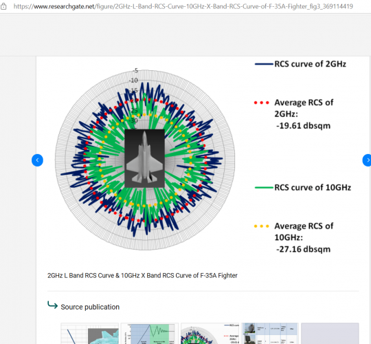
I am starting to wonder how many 6th gen designs will apply the same concept in making stealth aircrafts hunt other stealth aircrafts.
1743375663196.png
Depending on frequency range of bands and angles the size of RCS returns on radar can be magnified by 10 times the amount. I am assuming most high-end fighter aircrafts have 20 kilowatts max power and performance range of 1m2-3m2 in a 120 degree azimuth search for 200kms and a 1m2-3m2 in a 2 degree beam search for 350-400kms. Even if the L-bands on the Su-57 don't match the main X-band in power the Su-57's own stealth to get a little closer to another adversary stealth aircraft in comparison to 4th gens makes the L-band tracking deadly.

I do hope we get some news on what kind of avionic enhancements the Su-57M has undergone.
 
I am starting to wonder how many 6th gen designs will apply the same concept in making stealth aircrafts hunt other stealth aircrafts.
View attachment 765143
Depending on frequency range of bands and angles the size of RCS returns on radar can be magnified by 10 times the amount. I am assuming most high-end fighter aircrafts have 20 kilowatts max power and performance range of 1m2-3m2 in a 120 degree azimuth search for 200kms and a 1m2-3m2 in a 2 degree beam search for 350-400kms. Even if the L-bands on the Su-57 don't match the main X-band in power the Su-57's own stealth to get a little closer to another adversary stealth aircraft in comparison to 4th gens makes the L-band tracking deadly.

I do hope we get some news on what kind of avionic enhancements the Su-57M has undergone.

''The greater the wavelength is ,longer is the detecting/tracking distance''. L-Band AESA has 8 times greater wavelength than X- band AESA ( 24cm vs 3 cm).

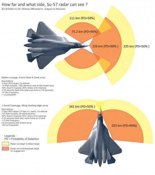
'Stealthflanker' made some calculations here 5 years ago ( page 39).

N036Estimate-8-13-2020.png

That was in August 2020 but NPP Pulsar made four-channel TRM's with max output pulse power per channel of 700W even 15 years ago. Su-57 of course has 4 linear L-band AESA ( 2 in wingslats and two in LEVCON's) and each 1.6 m wide antenna has in fact 24 radiating elements in the two rows. That is in total,12 RE can be used for the given position of the wingslats/LEVCON's. As mentioned before, L-Band AESA are 2D radars ( tracking by distance-azimuth) where data for elevation can come via data-link from air/ground assets. Again , '' the use of the L-band in air-to-air radar operation is the T-50's primary task of detecting stealth aircraft ''.

I 've found one comment and maybe someone can better explain what it is about...

''WHEN FULLY FUNCTIONAL AND MATURE, THIS L-BAND AESA RADAR HAS THE POTENTIAL TO BE A GAME CHANGER IN AERIAL WARFARE. FIRSTLY IT STANDS A BETTER CHANCE OF DETECTING FIGHTER-SIZED STEALTH AIRCRAFT COMPARED WITH ITS X-BAND COUNTERPARTS AS MOST LOW OBSERVABLE AIRCRAFTS HAVE DESIGNS OPTIMIZED FOR STEALTHINESS IN THE X-BAND. MANY STEALTH SHAPING FEATURES SUCH AS JAGGED EXHAUST NOZZLES, FACETED SURFACES AND SPECIALLY SHAPED ENGINE INLETS BECOME INEFFECTIVE IN THE CONTROLLED SCATTERING OF INCOMING RADAR WAVES WHEN THEIR SIZE APPROXIMATES THE WAVELENGTH OF THE INBOUND PULSE.SO A L-BAND RADAR MIGHT JUST PICK UP A FAINT SIGNATURE WHERE THE X-BAND SEES NOTHING.'
 
@ Null

It is interesting what Carlo Kopp wrote in his article from 2009 about the power of L-band AESA TRM's...

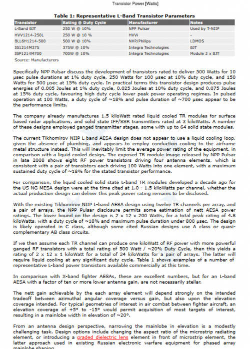
''With the existing Tikhomirov NIIP L-band AESA design using twelve TR channels per array, and a pair of arrays, the NPP Pulsar disclosure permits some estimation of nett AESA power ratings. If we then assume each TR channel can produce one kiloWatt of RF power with more powerful ganged RF transistors with a total rating of 500 Watt / ~20% Duty Cycle, then this yields a rating of 2 x 12 x 1 kiloWatt for a total of 24 kiloWatts for a pair of arrays.''

As we know now in that period ( 2009/2010/2011) ,NPP Pulsar achieved max output pulse power per channel of 700W with the news from 2011/12 that they increased the power to almost 1kW. What Carlo did not count is that Su-57 has four instead of two L-band AESA with a 48 RE's in total for the scanning in one given position of the wingslats/LEVCON's.
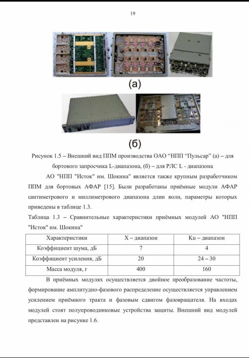

Material about RE of the L-band AESA developed under the Project known as 'Horseshoe'.

L-band broadband wide-angle AESA emitters

Problem statement:

The problem of designing emitters of a finite active phased antenna array (AESA) of one type is currently relevant. This AESA is characterized by high energy with wide-angle scanning in a wide frequency band
Objective:

To demonstrate the achievement of an unambiguous mutual understanding by developers and operators of the features of common emitters for the construction of energy-efficient broadband L-band AESAs with wide-angle scanning in two planes.
Results:

The existing technical solutions used in the construction of AESA operating in the decimeter wavelength range are analyzed. The features of the construction of AESA based on symmetric dipoles with a reflector, as well as AESA based on printed emitters are considered in general. An analysis of technical solutions used in the creation of vibrator phased array antennas was carried out, taking into account the requirements for the operating frequency band, ensuring coordination in the required sector of scanning angles, and ensuring the stability of the spatial directivity pattern/radar beam (DP) of the emitters in the array.

Practical significance:

Microstrip emitters and antenna arrays based on them are currently the de facto "standard" in the construction of broadband antennas.However, in the case of constructing highly efficient transceiver arrays in the decimeter frequency range with high pulse powers, the use of dipole-based emitters remains relevant (preferred).
 
''The greater the wavelength is ,longer is the detecting/tracking distance''. L-Band AESA has 8 times greater wavelength than X- band AESA ( 24cm vs 3 cm).
It is not that simple, otherwise all fighters would be using L band or even VHF band as radar.
While it's true that stealth fighters have a larger RCS at lower frequencies, there’s a trade-off. With the same aperture size, the lower the operating frequency, the broader the radar beam becomes. This not only reduces accuracy but also impacts directivity , essentially how focused the energy is. Think of the difference between a flashlight and a laser beam. Lower frequencies wave may travel farther, but that doesn’t necessarily translate to better detection range.
Also, the wider your radar beam is, the more likely that self propelled jammer like MALD-X, SPEAR-EW also located inside your main lobe while you looking at target and you can't use SLC or SLB technique to suppress their signal
 
Last edited:
It is not that simple, otherwise all fighters would be using L band or even VHF band as radar.
While it's true that stealth fighters have a larger RCS at lower frequencies, there’s a trade-off. With the same aperture size, the lower the operating frequency, the broader the radar beam becomes. This not only reduces accuracy but also impacts directivity , essentially how focused the energy is. Think of the difference between a flashlight and a laser beam. Lower frequencies wave may travel farther, but that doesn’t necessarily translate to better detection range.
Also, the wider your radar beam is, the more likely that self propelled jammer like MALD-X, SPEAR-EW also located inside your main lobe while you looking at target and you can't use SLC or SLB technique to suppress their signal
L-bands have less accuracy than X-band but are still used for fire control frequencies to track and hit targets from far away, also not counting that electronics for homing heads have improved for further lock on tracking distance capabilities. Is it possible for F-35s or F-22s to jam both L and X-band simultaneously using EW systems or their EW systems can only select one?

Edit: Also very important information I forgot to add. I think generally aircrafts will fly around with a 120-degree radar beam azimuth turned on. Lets say L-band is very useless in tracking to the point that air-to-air missile sensors on the missiles would not find the target if the Su-57s L-band radar pointed at a target from a specific direction. If both aircrafts are stealth and have 1m2 tracking capabilities from 200kms with a 120 degree X-band radar beam and still cannot see each other. The one also using L-band might be able to see the one that is just using X-band and switch its own 120 degree X-band to a 2 degree X-band radar beam to identify where the stealth target is on where the L-band radar found it.

I heard that an F-22 has something like 1m2 target tracking at a 200-240km distance and that it can use a 2 by 2 degree radar beam that would allow it to track the same target 1m2 at 400kms and of course a smaller RCS target than 1m2 can be tracked at 200kms with that same 2 by 2 degree radar beam. If two F-22s have seen each other as adversaries and are 400kms from each other facing in opposite directions, they would still not track each other. But if one got equipped with an L-band radar that F-22 would have a better chance tracking the other F-22 with it and if it is being tracked with that F-22 using L-band that same F-22 can use the 2 degree X-band radar beam to pin point it and track that F-22 1st with better accuracy before that F-22 tracks it back.
If using a 2 by 2 degree X-band radar beam off the bat from a far distance to track a target is like trying to find a needle in a haystack than the L-band can be used as a magnet.
 
Last edited:
L-bands have less accuracy than X-band but are still used for fire control frequencies to track and hit targets from far away, also not counting that electronics for homing heads have improved for further lock on tracking distance capabilities. Is it possible for F-35s or F-22s to jam both L and X-band simultaneously using EW systems or their EW systems can only select one?
Yes, you can use an L-band radar for fire control, but you'll need a significantly larger antenna. For example, if your X-band radar, operating at a 3 cm wavelength with a 90 cm aperture, has a beamwidth of 2.3 degrees, then to achieve the same beamwidth in L-band (30 cm wavelength), the required antenna diameter would need to be 9 meters.
Yes you can jam both L band and X band at the same times since you can drop multiple decoys. F-35 alone can use APG-81, ALE-70, Brite cloud, Spear-ew or MALD-X to jam.


Edit: Also very important information I forgot to add. I think generally aircrafts will fly around with a 120-degree radar beam azimuth turned on. Lets say L-band is very useless in tracking to the point that air-to-air missile sensors on the missiles would not find the target if the Su-57s L-band radar pointed at a target from a specific direction. If both aircrafts are stealth and have 1m2 tracking capabilities from 200kms with a 120 degree X-band radar beam and still cannot see each other. The one also using L-band might be able to see the one that is just using X-band and switch its own 120 degree X-band to a 2 degree X-band radar beam to identify where the stealth target is on where the L-band radar found it.

I heard that an F-22 has something like 1m2 target tracking at a 200-240km distance and that it can use a 2 by 2 degree radar beam that would allow it to track the same target 1m2 at 400kms and of course a smaller RCS target than 1m2 can be tracked at 200kms with that same 2 by 2 degree radar beam. If two F-22s have seen each other as adversaries and are 400kms from each other facing in opposite directions, they would still not track each other. But if one got equipped with an L-band radar that F-22 would have a better chance tracking the other F-22 with it and if it is being tracked with that F-22 using L-band that same F-22 can use the 2 degree X-band radar beam to pin point it and track that F-22 1st with better accuracy before that F-22 tracks it back.
If using a 2 by 2 degree X-band radar beam off the bat from a far distance to track a target is like trying to find a needle in a haystack than the L-band can be used as a magnet.
This is a common misconception about how radar works. A radar’s beamwidth is determined by its operating frequency and aperture size higher frequencies or larger apertures result in a narrower beam.
When a radar manufacturer states that a system has a 200 km range with a 120-degree search volume and a 400 km range with cued search, What they actually mean is that you when you reduce radar search volume, your dwell time at each beam position will increase. And that result in longer detection range because you integrate higher number of pulses together.
Yes, you can use an L-band radar to reduce the search volume of an X-band radar, effectively increasing X-band radar detection range. However, the reverse is also true. When operating any radar whether L-band or X-band you expose yourself to enemy ESM. And if they have sensor fusion, that ESM will also cue their radar toward your direction
 
And if they have sensor fusion, that ESM will also cue their radar toward your direction
Which is true, but L band emitter gets whole 255 deg picture in a faster scan; silent or no. Both can do frequency hopping(LPI) to complicate things, and shooting down su-57 is in any case massively more difficult than shooting down AWACS.

Opfor cues only on the emitter; rest of redfor maintains privilege of keeping silence.
This is a significant synergy with GBAD(and unified fuzed air situation), other felons(bystatics), and especially other redfor fighters (cued narrow search and engagement).

There is merit to aggressiveness, if one can survive it. If you're fighting a much larger LO force with inferior non-LO force, this is unavoidable risk, If you want to guarantee bluefor will be seen and engaged.
If you can live without it - no problem, but you'll end up as Iran, North Korea or Ukraine: spicy, but leaky. Saddam has shown potential consequences.

GBADs, normal fighters under ground control and AWACS will only get you so far; LO force will eventually disassemble them simply through superiority in initiative.

Otherwise, the only real option to provide robust defense is to aim at >1:1 force without discarding gbad. That's Soviet Union/China.
 
Last edited:
This is a common misconception about how radar works. A radar’s beamwidth is determined by its operating frequency and aperture size higher frequencies or larger apertures result in a narrower beam.
When a radar manufacturer states that a system has a 200 km range with a 120-degree search volume and a 400 km range with cued search, What they actually mean is that you when you reduce radar search volume, your dwell time at each beam position will increase. And that result in longer detection range because you integrate higher number of pulses together.
Yes, you can use an L-band radar to reduce the search volume of an X-band radar, effectively increasing X-band radar detection range. However, the reverse is also true. When operating any radar whether L-band or X-band you expose yourself to enemy ESM. And if they have sensor fusion, that ESM will also cue their radar toward your direction

1743523238499.png
Any turned on radar in general get exposed to ESM, it's not like most aircrafts in combat will use RWR and infrared as the main source to track targets. Unless you're telling me that RWRs are sufficient enough to cue any aircrafts radar beam to be narrower to point towards the target where the RWR will show where it's at?


Yes, you can use an L-band radar for fire control, but you'll need a significantly larger antenna. For example, if your X-band radar, operating at a 3 cm wavelength with a 90 cm aperture, has a beamwidth of 2.3 degrees, then to achieve the same beamwidth in L-band (30 cm wavelength), the required antenna diameter would need to be 9 meters.
Yes you can jam both L band and X band at the same times since you can drop multiple decoys. F-35 alone can use APG-81, ALE-70, Brite cloud, Spear-ew or MALD-X to jam.
Yeah but now you're talking about a radar much much larger than whatever the su57 can carry. This mythical "radar" function of the L-band arrays are more myth than physics. Be aware of some of these russian sources being just magazines, sites, and blogs much like the american TWZ.com rather than actual manufacturers' claims. And even then, it's not like russian manufacturers are not well known for lofty claims that are not backed with performances in the real world.

1743523664862.png
1743523900009.png
 
It is not that simple, otherwise all fighters would be using L band or even VHF band as radar.
While it's true that stealth fighters have a larger RCS at lower frequencies, there’s a trade-off. With the same aperture size, the lower the operating frequency, the broader the radar beam becomes. This not only reduces accuracy but also impacts directivity , essentially how focused the energy is. Think of the difference between a flashlight and a laser beam. Lower frequencies wave may travel farther, but that doesn’t necessarily translate to better detection range.
Also, the wider your radar beam is, the more likely that self propelled jammer like MALD-X, SPEAR-EW also located inside your main lobe while you looking at target and you can't use SLC or SLB technique to suppress their signal

We have now almost complete translated document under the Project ''The scale'' .Did you read it ?
 
Yeah but now you're talking about a radar much much larger than whatever the su57 can carry. This mythical "radar" function of the L-band arrays are more myth than physics. Be aware of some of these russian sources being just magazines, sites, and blogs much like the american TWZ.com rather than actual manufacturers' claims. And even then, it's not like russian manufacturers are not well known for lofty claims that are not backed with performances in the real world.

Mythical ,yes. We have some things now that are not from 'magazines, sites, and blogs' but from the NPP 'Pulsar' as the manufacturer of the TRM's for the L-band AESA.

So four-channel TRM has next working channels ( again):

Channel no 1 : IFF under the international standard ( NATO standard Mk-12).
Channel no 2: long range search/detect/track radar
Channel no 3: IFF under the state standard ( Parol system)
Channel no 4: ECM/interference signals as part of the L402 Himalay jamming system.
 
1743525868924.png
1743525911909.png
1743526208709.png
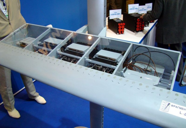
So the wing serves as the L-band antenna, but the modules of it are displayed in past exhibition of where it would be located in the wings?
 
Yes, I know what the common magazine wrote about the so called cued search. But like I already explained to you. It is a misconception. They are confusing between the angular search volume and the beam width.
Beam width is a physical quantity that is limited by operating frequency and aperture area, and you can calculate that value. Whereas volume search is something that can be reduced in size so your dwell time is longer

Any turned on radar in general get exposed to ESM, it's not like most aircrafts in combat will use RWR and infrared as the main source to track targets. Unless you're telling me that RWRs are sufficient enough to cue any aircrafts radar beam to be narrower to point towards the target where the RWR will show where it's at?
Not all RWR are created equal.
Take for example: SPO-15 can only give general direction of threat and threat type
IMG_8339.png

By contrast, more modern ESM system such as ASQ-213 R7 is accurate enough to guide PGM to target

IMG_8340.jpeg

The answer to your question is: yes, modern ESM can cue radar to point toward target. It is even easier for them if adversary radar has a wide beam width.

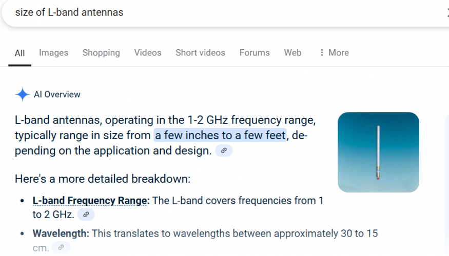
You are confused between the size of individual L-band antenna, and the size of the radar aperture which made from multiple individual L-band antenna.
Individual antenna can be as small as 1/4 or even 1/8 wavelength (just look at how small the antenna on mobile phone are).
But if you want directivity, your radar aperture need to be of a certain size. If you want your radar beam width to be small enough for targeting, then your L-band need to be quite big
IMG_8342.jpeg
 
We have now almost complete translated document under the Project ''The scale'' .Did you read it ?
Yes, I've seen some of your posts, but to be honest, without the original document's proper formatting such as tables, images, and illustrations it's difficult to draw a clear conclusion. Right now, it feels like a mix of multiple different articles rather than a cohesive analysis
It probably better if you just screenshot the document and let people use google translate to read it.
 
You are confused between the size of individual L-band antenna, and the size of the radar aperture which made from multiple individual L-band antenna.
Individual antenna can be as small as 1/4 or even 1/8 wavelength (just look at how small the antenna on mobile phone are).
But if you want directivity, your radar aperture need to be of a certain size. If you want your radar beam width to be small enough for targeting, then your L-band need to be quite big
IMG_8342.jpeg
So a bigger aircraft, there are AWACS that have bigger X-band radars.
 
Yes there are, that just mean the beam width is even smaller and therefore more accurate
Speaking of accuracy, I think the performance of the L-band accuracy was listed unless you agree with the calculations on this source?
1743529008774.png
1743529090750.png
1743529212332.png
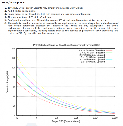
At least they estimated 40-70 nautical miles for a 1m2 target but that is with the use of L-band and still state room for increased performance if they added higher power and more modules in the last paragraph of that page.
 
View attachment 765320
View attachment 765321
View attachment 765326
So the wing serves as the L-band antenna, but the modules of it are displayed in past exhibition of where it would be located in the wings?

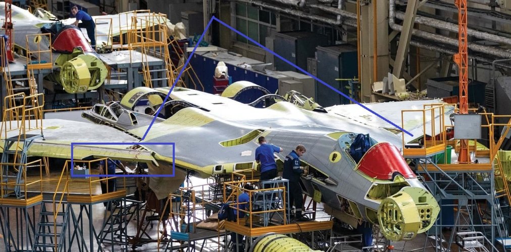
In fact ,1.6 wide L-band AESA ( antennas) are part of the wingslats and LEVCON's. On those photos we can see complete AESA with its radiating elements and TRM's of course . Take a look on this photo frome the KnAAZ. We can see the places inside of the wingslats where those two L-band AESA will be attached.

Su-57 in KnAAZ 1 mod.jpg
 
So a bigger aircraft, there are AWACS that have bigger X-band radars.

AWACS aircraft have in fact decimetric L or centimetric S-band search/detect/track radars with of course L-band used also for the IFF/ID.
 
Speaking of accuracy, I think the performance of the L-band accuracy was listed unless you agree with the calculations on this source?
View attachment 765332
View attachment 765333
View attachment 765334
At least they estimated 40-70 nautical miles for a 1m2 target but that is with the use of L-band and still state room for increased performance if they added higher power and more modules in the last paragraph of that page.

This citation is from that article wrote by dr Carlo Kopp in 2009 .

  1. ''TR module nominal power rating of 200 Watts per TR channel, for a total of 2.4 kiloWatts per array, and 4.8 kiloWatts for a two array installation.''
About twenty years ago NPP Pulsar achieved on the static tests max output pulse power ( for the Channel no2) of about 400W / in fact in the range of 360-540W) in the search radar mode. Then on 2010 they increased that power to level of 700W. After 2010 they increased that power to the level of almost 1kW.
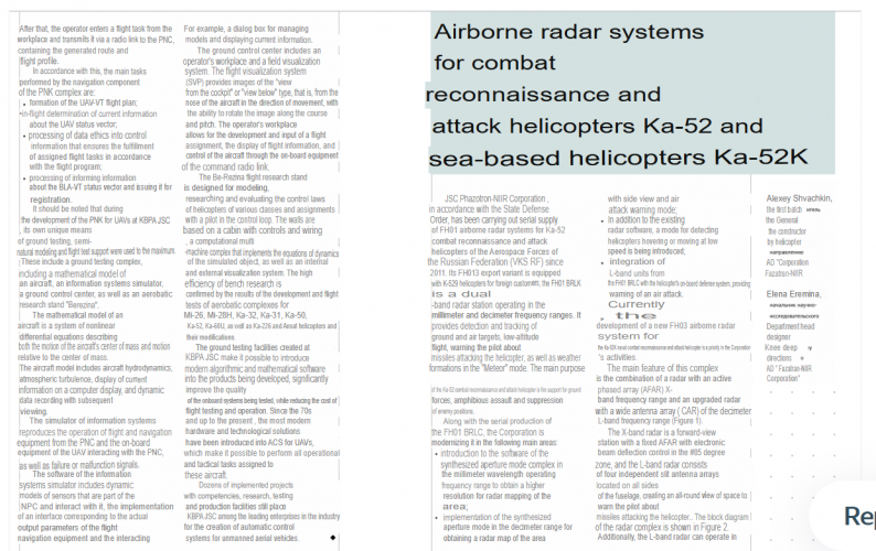
 
I cant find it because KRET deleted all their articles when the Ukraine war started but the google search function did give me this.
https://www.secretprojects.co.uk/threads/kamov-projects.2766/page-7 see post 279
1743530571545.png
and this
1743530060154.png
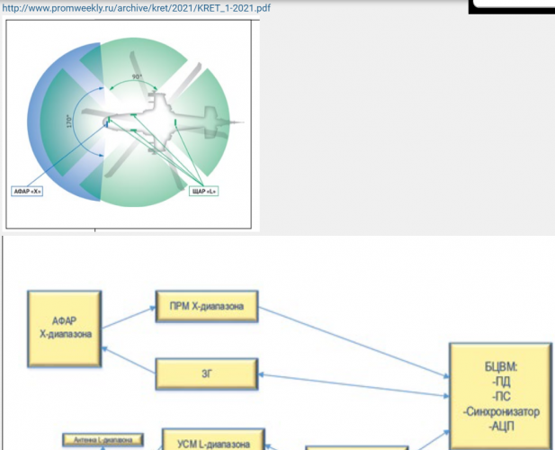
but they have shown in their magazine PDFs that they also used X and L-band radars for their helicopters, and I think helicopters dont have to be as big as AWACS aircrafts which gives reassurance that the L-bands on the Su-57 do indeed serve as a radar function to track targets.

L-band radars do have to have some benefits if they are sticking it in military assets that can fly and not sticking it in just for the fun of it.
 
I cant find it because KRET deleted all their articles when the Ukraine war started but the google search function did give me this.
https://www.secretprojects.co.uk/threads/kamov-projects.2766/page-7 see post 279
View attachment 765337
and this
View attachment 765336
but they have shown in their magazine PDFs that they also used X and L-band radars for their helicopters, and I think helicopters dont have to be as big as AWACS aircrafts which gives reassurance that the L-bands on the Su-57 do indeed serve as a radar function to track targets.

L-band radars do have to have some benefits if they are sticking it in military assets that can fly and not sticking it in just for the fun of it.
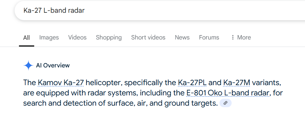
It is in fact the Kamov Ka-31 with the underfuselage rotatable radar E-801 Oko ( eye).

 
Last edited:
Since they love to stick radars with different bands on helicopters and aircrafts it seems I have received this news today and find it very relevant if they are going to stick radars working in K-band or higher later for the Su-57.
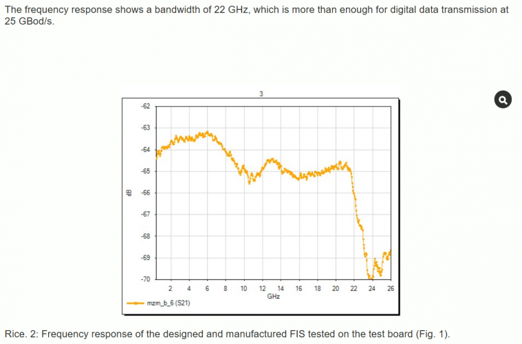
The Fistech startup, created on the basis of Skoltech, was the first in Russia to design and successfully test photonic integrated circuits for working with high-frequency signals with a bandwidth of up to 22 GHz. The development is aimed at providing Russian manufacturers with telecommunications solutions based on domestic FIS. The project was implemented with the support of the Ministry of Industry and Trade of Russia, Skoltech, and the Skolkovo Foundation.

Fistech is a participant in the Skolkovo project and is working on the development and market launch of domestic modules based on photonic integrated circuits for optical communication systems of its own design. Such FIs are applicable in coherent optical communication systems with a bandwidth of up to 100 Gbit/s per wavelength in the DP-QPSK format. The FIS functionality was tested on completely domestic test boards created within the framework of the project, which allow working with high-frequency signals over 40 GHz.

The manufactured photonic chips were integrated onto test boards with the participation of ZNTC JSC and tested with the support of the Center for Shared Use of the National Research Center "Kurchatov Institute" (NIISI), NRNU MEPHI, LLC T8, and the Skoltech Laboratory of Integrated Photonics.
1743554829864.png
Currently, the second stage of testing is being completed - testing the IQ modulator supporting the QPSK format and the coherent receiver. These modules are integrated with modulator drivers and transimpedance amplifiers to improve eye pattern quality and transmission stability. The completion of tests is expected in early June 2025.
  • Smaller waves than X-band with PIC transceiver modules could be used on radar antennas to function as radars and offer better tracking precision along with tracking stealth depending how far they will go raising the frequency because they successfully tested a PIC working as a transceiver works with sending and receiving 22ghz radio signals as means for digital data communication.
  • Su-57 can be offered with long range communication that can transfer large amounts of data.
  • Could function as RWR/EW use and depending on the operating frequency of the PIC modules they can jam incoming air to air missile radar heads that track targets based on the frequencies they use which are higher than X-band.
 
Speaking of accuracy, I think the performance of the L-band accuracy was listed unless you agree with the calculations on this source?
At least they estimated 40-70 nautical miles for a 1m2 target but that is with the use of L-band and still state room for increased performance if they added higher power and more modules in the last paragraph of that page.
Carlo Kopp's calculations are generally solid, but his conclusions can be questionable due to his strong bias toward the F-22 and the F-111 fleet

It is in fact the Kamov Ka-31 with the underfuselage rotatable radar E-801 Oko ( eye).

Yes, but E-801 is a lot bigger than the individual L-band array on Su-57.
Firstly, it has like 4 row of L band transmitter in the vertical, that mean it can determine target altitude whereas L band on leading edge of su-57 can't scan vertically
Secondly, the length of E-801 is about 6 meters whereas length of individual L band on Su-57 is about 1.6-1.8 meters

This citation is from that article wrote by dr Carlo Kopp in 2009 .

  1. ''TR module nominal power rating of 200 Watts per TR channel, for a total of 2.4 kiloWatts per array, and 4.8 kiloWatts for a two array installation.''
About twenty years ago NPP Pulsar achieved on the static tests max output pulse power ( for the Channel no2) of about 400W / in fact in the range of 360-540W) in the search radar mode. Then on 2010 they increased that power to level of 700W. After 2010 they increased that power to the level of almost 1kW.
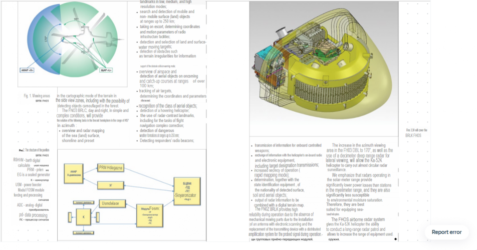
Having a more powerful radar is not just a simple case of adding more powerful T/R elements, cooling is very important. Changing from 4.8 kW to 24 kW total is quite a significant increase in term of cooling.
 
Last edited:
Carlo Kopp's calculations are generally solid, but his conclusions can be questionable due to his strong bias toward the F-22 and the F-111 fleet


Yes, but E-801 is a lot bigger than the individual L-band array on Su-57.
Firstly, it has like 4 row of L band transmitter in the vertical, that mean it can determine target altitude whereas L band on leading edge of su-57 can't scan vertically
Secondly, the length of E-801 is about 6 meters whereas length of individual L band on Su-57 is about 1.6-1.8 meters


Having a more powerful radar is not just a simple case of adding more powerful T/R elements, cooling is very important. Changing from 4.8 kW to 24 kW total is quite a significant increase in term of cooling.
This discussion on Su-57 avionics should be moved to its own topic in Avionics section.

Speculation on random components with zero link to Su-57 don't even below in an Su-57 avionics discussion.
 
Yes there are, that just mean the beam width is even smaller and therefore more accurate

About the beam width of the L-band PESA/AESA we have data in the mentioned doc.( transl. page 7 and 8).

Carlo Kopp's calculations are generally solid, but his conclusions can be questionable due to his strong bias toward the F-22 and the F-111 fleet


Yes, but E-801 is a lot bigger than the individual L-band array on Su-57.
Firstly, it has like 4 row of L band transmitter in the vertical, that mean it can determine target altitude whereas L band on leading edge of su-57 can't scan vertically
Secondly, the length of E-801 is about 6 meters whereas length of individual L band on Su-57 is about 1.6-1.8 meters


Having a more powerful radar is not just a simple case of adding more powerful T/R elements, cooling is very important. Changing from 4.8 kW to 24 kW total is quite a significant increase in term of cooling.

Hm,when prototype number 055 blue began flying from 2013,it was equipped with four L-band AESA where each TRM had four channels with min 500W of max output pulse power per channel ( DC about 30%).Keep on mind that channel no2 ( radar channel) got increased max output pulse power to 700W from 2010. So if we speak about total max output pulse power for all four antennas ,we have 48 RE ( radiating elements) for a total of 48 working channels where min pulse power was maybe 500W and max maybe even 1kW (from 2013).That was in total 24 kW of pulse power (assumption for the pulse power of 500W e.g.as average ) but we must keep on mind that from four working channels, only one is for the real radar mode. So we have 12 'radar channels' in total of four L-band antennas with max pulse power maybe 12 kW ( if we speak about real flight tests from 2013).

Another material from the NPP 'Pulsar' as the manufacturer of those TRM's :

''JSC NPP Pulsar has developed a series of L-band TRM's for onboard AESA . The modules are 4-channel, each TRM includes a signal processor that controls the amplitude and phase of the TRM, as well as the primary processing of information.
The output power of the TRM is hundreds of W, the phase shifter bit depth is from 5 to 7 bits, the attenuator adjustment range is about 25 dB. The appearance of the TRM is shown in Figure 1.5.''

What we have here is in fact TRM for the on-board digital interrogator with decimetric L-band AESA type 4283MP for the Su-35S ( a ) and the TRM for the L-band AESA (PESA) for the Su-57 ( b).

TRM's.jpg

''Figure 1.5 – External appearance of the TRM manufactured by JSC NPP Pulsar (a) – for the L-band on-board interrogator, (b) – for the L-band radar.''

Again: Overall dimensions of the TRM (HxWxD), no more: 70x1650x90 mm,volume: 2.5l, weight: about 4kg.

I already wrote about this and gave translated page for this material about static tests of the prototype model of TRM for the L band AESA.What we can see is that total max output pulse power for the one TRM ( with all four channels) was 1800W or 450W for the each channel with DC 25-32% for the so called radar channel. Each antenna has three TRM's so that was 5400W or in total 21600W for all four antennas . On the bottom is the photo of the model of TRM w/o its cover.

TRM L band AESA  1.jpg

TRM L band AESA  2.jpg

@overscan

Sorry but I coudn't find that topic.
 
Last edited:
About the beam width of the L-band PESA/AESA we have data in the mentioned doc.( transl. page 7 and 8).
To be honest, the wording of that document is quite confusing when translate from Russia to English
But if I understand it correctly, the elevation beam width is 70-90 degrees while the azimuth beamwidth is 30 degrees?.
Hm,when prototype number 055 blue began flying from 2013,it was equipped with four L-band AESA where each TRM had four channels with min 500W of max output pulse power per channel ( DC about 30%).Keep on mind that channel no2 ( radar channel) got increased max output pulse power to 700W from 2010. So if we speak about total max output pulse power for all four antennas ,we have 48 RE ( radiating elements) for a total of 48 working channels where min pulse power was maybe 500W and max maybe even 1kW (from 2013).That was in total 24 kW of pulse power (assumption for the pulse power of 500W e.g.as average ) but we must keep on mind that from four working channels, only one is for the real radar mode. So we have 12 'radar channels' in total of four L-band antennas with max pulse power maybe 12 kW ( if we speak about real flight tests from 2013).
I'm very confused by your calculation.
Where did you get the maximum and minimum output per channel? Is it specially mentioned for Su-57 radar or is it a generic L-band? Did you simply multiply the individual output of each channel to determine the output of each TR module, and then multiply again to calculate the radar's total output?. If they are already in separate channel let say jamming/IFF/radar..etc what make you think their peak power can be grouped together for radar?
Additionally, considering that the L-band arrays on the left and right sides of the aircraft have minimal overlap due to the field of views nature of ESA why are you counting their peak power together?
Another material from the NPP 'Pulsar' as the manufacturer of those TRM's :
''JSC NPP Pulsar has developed a series of L-band TRM's for onboard AESA . The modules are 4-channel, each TRM includes a signal processor that controls the amplitude and phase of the TRM, as well as the primary processing of information.
The output power of the TRM is hundreds of W, the phase shifter bit depth is from 5 to 7 bits, the attenuator adjustment range is about 25 dB. The appearance of the TRM is shown in Figure 1.5.''
What we have here is in fact TRM for the on-board digital interrogator with decimetric L-band AESA type 4283MP for the Su-35S ( a ) and the TRM for the L-band AESA (PESA) for the Su-57 ( b).
''Figure 1.5 – External appearance of the TRM manufactured by JSC NPP Pulsar (a) – for the L-band on-board interrogator, (b) – for the L-band radar.''
Again: Overall dimensions of the TRM (HxWxD), no more: 70x1650x90 mm,volume: 2.5l, weight: about 4kg.
I don't quite understand your point here?
I see they said a is L band T/R module for IFF and b is for radar, but what part does it say the L band on either Su-35 or Su-57?
 
Last edited:
This is getting rather confusing; I thought the initial arguments were something along the lines that L-band radars have to be big in order to function which is why a large passenger size aircraft was brought up as an example, but there is also clear evidence that Kamov helicopters operate using dual X and L band radars to track targets. One thing is not like the other.
 
To be honest, the wording of that document is quite confusing when translate from Russia to English
But if I understand it correctly, the elevation beam width is 70-90 degrees while the azimuth beamwidth is 30 degrees?.

I'm very confused by your calculation.
Where did you get the maximum and minimum output per channel? Is it specially mentioned for Su-57 radar or is it a generic L-band? Did you simply multiply the individual output of each channel to determine the output of each TR module, and then multiply again to calculate the radar's total output?. If they are already in separate channel let say jamming/IFF/radar..etc what make you think their peak power can be grouped together
Additionally, considering that the L-band arrays on the left and right sides of the aircraft have minimal overlap due to the field of views nature of ESA why are you counting their peak power together?

I don't quite understand your point here?
I see they said a is L band T/R module for IFF and b is for radar, but what part does it say the L band on either Su-35 or Su-57?

Yes, you have the translation of the pages no 7 and 8 where we have data about beamwidth.

Data in that two tables are from the static tests ( period 2005-2006) of the TRM for the L band AESA for Su-57. It is simple because there is description about values for the radar and for the IFF channel ( modes) . About total peak power as I already wrote ,we must keep on mind that there are only one real radar channel per TRM. So we have 12 radar channels in total ( if we speak only about decimetric radar posibilities). Btw, L band AESA have 110° of azimuthal FoV.

All data are from NPP Pulsar as manufacturer of the TRM for the L band AESA .Yes ,for the IFF L band AESA for Su-35S and for the combined IFF/radar/jamm L band AESA for the Su-57. On the mini-photo (a) we can see TRM for the L band AESA of the IFF interrogator for the Su-35S and on the mini photo (b) is the TRM for the L band AESA of the Su-57.
 
This is getting rather confusing; I thought the initial arguments were something along the lines that L-band radars have to be big in order to function which is why a large passenger size aircraft was brought up as an example, but there is also clear evidence that Kamov helicopters operate using dual X and L band radars to track targets. One thing is not like the other.
You misunderstood the argument. A lower frequency radar need to be bigger to achieve the same level of accuracy as a radar working at higher frequency. For example, if your X-band radar, operating at a 3 cm wavelength with a 90 cm aperture, has a beamwidth of 2.3 degrees, then to achieve the same beamwidth in L-band (30 cm wavelength), the required antenna diameter would need to be 9 meters. That the reason why L band, VHF band , HF band are much bigger compared to X band, Ka band radar. A L band working as fire control radar would be very big
Taking practical example:
E-801 L-band radar on Ka-31 helicopter is very big compared to V006 rzet X band radar on Ka-52M, it is also much bigger compared to the L band on Su-57, the aperture area of E-801 is about 53 times bigger compared to the leading edge L band on Su-57
 
Yes, you have the translation of the pages no 7 and 8 where we have data about beamwidth.
alright, what is the beamwidth value? can you maybe screenshot the line about beamwidth?
Due to the formatting of the translator and maybe the wording in Russia, it quite hard for me to fully understand what that document trying to say. From the translator, it looks to me like they were listing various requirement about scanning sector, field of regard, output power, sidelobe level ..etc. I can't seem to find anywhere they made a mention of azimuth beamwidth
Data in that two tables are from the static tests ( period 2005-2006) of the TRM for the L band AESA for Su-57. It is simple because there is description about values for the radar and for the IFF channel ( modes) . About total peak power as I already wrote ,we must keep on mind that there are only one real radar channel per TRM. So we have 12 radar channels in total ( if we speak only about decimetric radar posibilities).
When I replied, your post didn't have two table, that why I was confused with the value.
So basically 500W peak per T/R module for radar?
Is there any information about their cooling requirement?

Btw, L band AESA have 110° of azimuthal FoV.
So quite similar to most ESA basically.
 
@Squirrel you are very close to a post ban.

1) Post sources for your "article translations". This should be the name of the article and source, this can be in Russian. Links to the originals would be useful if available, or post the test in Russian with a translation afterwards.
2) Check whether it in some way is relevant to the topic of Su-57 avionics. The existence of a thing in a lab and the presence of a thing in a production Su-57 are two very different things.
3) Read your translations and post conclusions and questions

Otherwise its just a spam dump of contextless words with no attribution or analysis. Garbage.
 
Last edited:
Yes, you can make a small L band AESA antenna with small numbers of modules, but the width of the radar beam formed will be very wide. For IFF or EW this probably isn't an issue but as a radar this will make any target locations gathered from it pretty imprecise.

As far as I can gather the Su-35 L band antenna has no elevation scanning at all, so you couldn't actually tell how high the target you detected is. With a 1.2m antenna width, even in azimuth it won't be super precise about azimuth angle either. Not sure if the Su-57 improves here.

It doesn't make it worthless to explore such a capability as part of sensor fusion, but its not some kind of revolutionary way to put an AWACS radar in a fighter.
 
You misunderstood the argument. A lower frequency radar need to be bigger to achieve the same level of accuracy as a radar working at higher frequency. For example, if your X-band radar, operating at a 3 cm wavelength with a 90 cm aperture, has a beamwidth of 2.3 degrees, then to achieve the same beamwidth in L-band (30 cm wavelength), the required antenna diameter would need to be 9 meters. That the reason why L band, VHF band , HF band are much bigger compared to X band, Ka band radar. A L band working as fire control radar would be very big
Taking practical example:
E-801 L-band radar on Ka-31 helicopter is very big compared to V006 rzet X band radar on Ka-52M, it is also much bigger compared to the L band on Su-57, the aperture area of E-801 is about 53 times bigger compared to the leading edge L band on Su-57
1743712763472.png
1743712998427.png
BRLC FH03 radar consists of 4 slot L-band arrays and one X-band slot array in the front. it can search for detection of moving and stationary surface (ground) objects at ranges of up to 250 km. Detects air objects passed 100 kms. I am assuming the L-band arrays on the Su-57 wings are far bigger than the 4 L-band arrays on the helicopter they are talking about.
The L-bands they are talking about sound like they are used for radar surveillance
The increase in the FH03 radar's azimuth coverage area to 170°, as well as the use of a decimeter-range radar for lateral scanning, will allow the Ka-52K helicopter to carry out virtually all-round radar surveillance.
1743714491747.png
1743714541757.png
The L-band they state can detect objects camouflaged in the forest or be used as air surveillance, I am assuming the 100km+ is what they are referencing for the L-band and 250kms for the X-band. Maybe the antenna size and power range would put the L-band tracking capabilities to be efficient at 200kms but anything past that as imprecise?
 

Please donate to support the forum.

Back
Top Bottom