On the previous page we have now almost complete translation of the doc. about the Project 'The Scale' that is in connection with the development of the decimetric L band AESA N036L. I forgot that I have some translations of the articles from 2008/2009/2010/2011 about those L band AESA. Here they are:
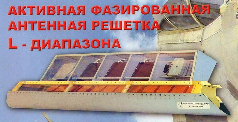
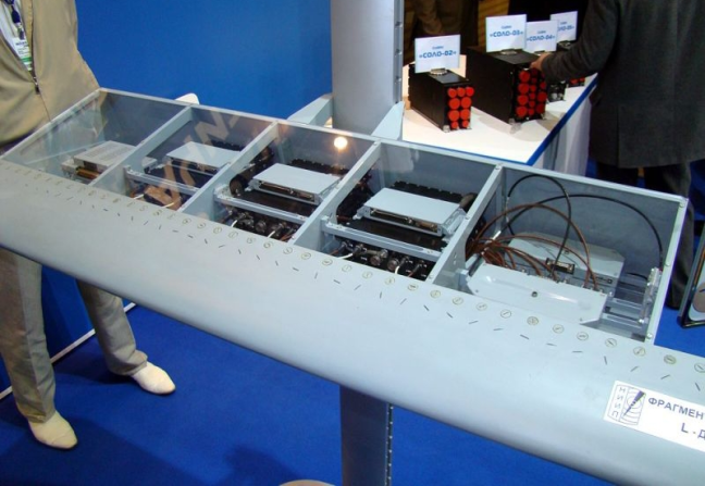
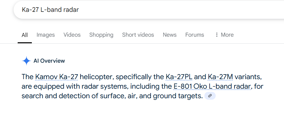
These are the test results conducted about 20 years ago ( real tests of the L-band AESA prototype antenna in NIIP named after V.V Tikhomirov) .Source is one article of NPP 'Pulsar' from 2008. Mentioned before the model of L-band AESA was first publicly shown on MAKS-2007.
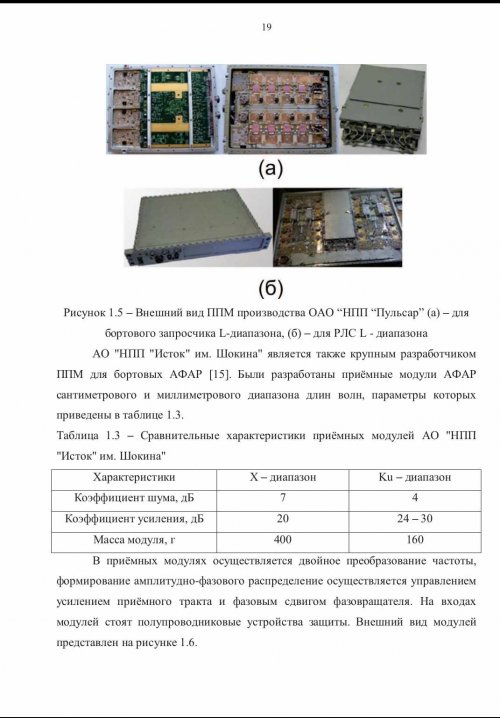
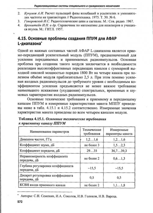
The main problems of creating TRM's for the L-band AESA
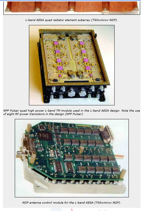
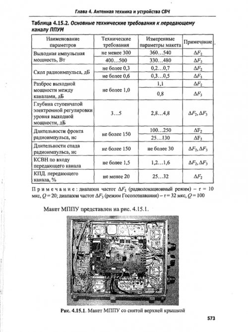
''One of the important components of the L-band AESA is the transmit-receive amplifier module (TRAM), designed to amplify transmitted and received radio pulses.The main problem in creating such a module is the need to implement highly efficient transmission channels with a total output peak power of about 1800 W per four channels with a useful module volume of approximately 2.5 l . In addition to amplifying the input radio pulses to the required level with the required gain, an equally important requirement is the least distortion (deterioration) of the spectral, temporal and noise characteristics of the input radio pulses. The main technical requirements for the receiving and transmitting channels of the PPUM/TRM and the measured characteristics of the model of the TRM are given below in Tables 1 and 2, respectively. The measured values of the characteristics of the breadboard are given for all four channels of the module.
Table 1
Basic technical requirements for the receiving channel of the TRM
Name of parameters : Frequency range, GHz ... Technical requirements : 1.2-1.6 , Measured parameters of the test model : 1.2-1.6
Noise figure, dB ... Technical requirements : 3 , Measured parameters of the test model :1.5-2.3
Transmit coefficient, dB ... Technical requirements : 29-35 , Measured parameters of the test model :36.7-39.3
Unevenness of the transmission coefficient, dB Technical requirements : no more than 2 , Measured parameters of the test model : 0.6-1.3
Gain adjustment depth, dB ...Technical requirements : -15.5 , Measured parameters of the test model : -15.5
Discreet adjustment of the transmit coefficient, dB...Technical requirements :0.5 , Measured parameters of the test model 0.5
VSWR input of the receiving channel ....Technical requirements : no more then 2 ,Measured parameters of the test model : 1.1-1.8
Table 2
Basic technical requirements for the transmitting channel of the TRM
Name of parameters: Output impulse power, W ..Technical requirements : no less than 300 ( for radar mode) and 400-500 ( for IFF mode) ,Measured parameters of the test model : 360-540 ( for radar mode) and 330-480 ( for IFF mode)
Chip of radio pulse, dB..Technical requirements : no more than 0.3 ( for radar mode) and 0.6 ( for IFF mode) ,
Measured parameters of the test model : 0.2-0.7 ( for radar mode) and 0.3-0.5 ( for IFF mode )
The spread of the output power between channels, dB...Technical requirements : no more than 1.0 , Measured parameters of the test model : 1.1 ( for radar mode) and 0.8 ( for IFF mode)
Depth of step electronic output power level control, dB ....Technical requirements :3-5 ( for both modes) ,Measured parameters of the test model : 2.8-4.8 ( for both modes )
The duration of the front of the radio pulse, ns(nanosec).. .Technical requirements : no more than 150 ( for both modes) , Measured parameters of the test model : 100-250 ( for radar mode) and 25-130 ( for IFF mode)
The duration of the falloff of the radio pulse, ns ..Technical requirements : no more than 150 ,Measured parameters of the test model : no more then 30 ( for both modes )
VSWR at the input of the transmitting channel...Technical requirements :no more than 1.5 ,Measured parameters of the test model : 1.2-1.6 ( for both modes)
Efficiency( Duty Cycle ) of transmission channel,% ...no less than 20 , Measured parameters of the test model: 25-32 for the radar mode.
Note: frequency range ΔF2 (radar mode) - τ = 10 μs, Q = 20; frequency range ΔF3 (IFF mode) - τ = 32 μs, Q = 100 .''
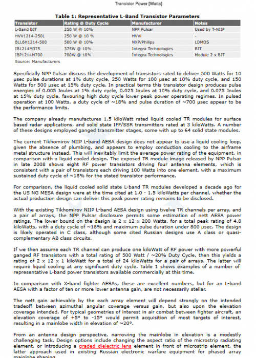
It is interesting that Carlo Kopp wrote in his article from 2009 that Duty Cycle is ~20% but several years earlier ,the test model ( prototype of L-band AESA) had 25-32 % of the DC .
From another article ( 2009 ) :
L-band multichannel broadband microwave transmit-receiver module for airborne radar with AESA .
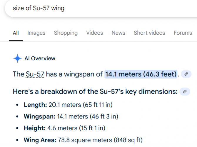
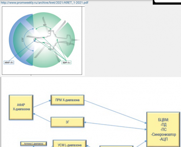
''The modules are 4-channel, each TRM includes a signal processor that controls the amplitude and phase of the TRM , as well as primary information processing. The output power of the TRM is hundreds of W, the capacity of the phase shifters is from 5 to 7 digits, the range the adjustment of the attenuators is about 25 dB.Overall dimensions (HxWxD), no more: 70x1650x90 mm, which are additionally limited by the shape of the available space under the nose fairing .The features of assessing monostatic and bistatic AESA are considered. Numerical algorithms have been tested and a diagram of the backscattering of a phased array from log-periodic and monopole emitters of the decimeter range with an operating frequency range of 1 ... 1.6 GHz is presented when irradiated with a wave of the centimeter range in the band 8.5 ... 12.5 GHz. It is known that the sweep angle of the Su-57 wing is approximately 48°, therefore, to view the radar in the forward direction, it is necessary to deflect the beam at least by the same angle. Max Pulse power per element 500W. Average power per element 250W .The preferred number of elements in the radiating system is 12.''
This is another article about L-band AESA ( also from 2009 );
ON-BOARD LINEAR AESA OF DECIMETRIC BAND
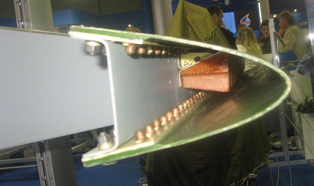
''When placing antennas together decimeter and centimeter wavelengths, a number of problems arise - a largewidth of the radar beam of PESA-AESA for IFF does not allow obtaining a sufficient angular resolution. Moreover, combining emitters of two AESA in a single aperture causes mutual distortion of antenna characteristics. When switching from passive ESA to AESA , difficulties arise in combining two antennas inone aperture. Therefore, the question arises about the possibility of autonomous execution of AESA IFF.In the course of a detailed analysis of the surfaces of modern and future aircraft, it wasrevealed that the most promising is the placement of the AESA IFF in the leading edge of the wing. A rather extended aperture with a length of up to 10λ can be placed in the wing tip, which will be able to provide the required angular resolution in one plane - in azimuth. In practice, this is quite sufficient, despite the lack of angular resolution in the plane elevation angle.In addition, there is the possibility of placing on board not one, but two AESA , which expands the scanning sector of the radar- IFF antenna.
Considering that the constituent AESA blocks have sufficient broadband, AESA can perform the functions of multiple antennas. Considering the positive aspects of placing the IFF antenna in a movable nose wing, do not forget about the strict restrictions on the overall dimensions of the blocks,imposed by such an extraordinary placement. Temperature conditions at variousflight modes and mechanical effects on the blocks create additional difficulties fordevelopers.For example, the temperature in the leading edge of the wing tip can reach + 180°С,and the mechanical loads ( g load) are at least 5.5g. Therefore, special attention waspaid to the development of the emitter, which should form a given DN, taking into account the influence of closely spaced fairing and maintain performance in harsh climatic conditions.Autonomous placement of the IFF antenna assumes a fairly long cable network.
Considering the amount of attenuation in the coaxial conductor, to ensure the requiredenergy parameters, it is necessary to install a powerful transmitter on board. It has becomeone of the reasons for the implementation of the IFF antenna using the AESA technology is the inclusion in the antenna active module.The classic performance of the active modules that make up the AESA assumes monolithic design options. In most cases, it is justified, however, when working in the decimeter wavelength range, the dimensions of the module become rather bulky.Therefore, the AESA IFF is built according to the following scheme: the signal received by the emitting systemamplified in the receiving channel of the module, phase shifters made by a separate device,provide the necessary phase shift in each channel, then the signal from each channelsummed in power dividers. AESA is controlled by the control unitantenna (ACU), the main task of which is the calculation of phase codes and controlphase shifters AESA, i.e. providing electronic scanning with a beam.
All feeding voltages are supplied to the units from a secondary power source.AESA modular design allows compact placement in one wing compartmentactive modules, and in the other - distribution and phasing devices (URF), anddiagram-forming device (DOU). In addition to being compact, such a construction schemeallows you to easily switch from the active version of the antenna to the passive ESA( from AESA to PESA ) , by means of simple exclusion of the amplifier modules from the circuit. All other blocks designed inNIIP are based on proven technologies and can be used for its intended purposein almost any version of the PAR (phased array radar ) . Description of the construction of blocks and their characteristics are given in the full text of the report.The main stages of setting up / working with AESA are:- measurement of the characteristics of active (transceiver) modules;- writing to the flash-memory of control devices (CU) of the necessary correctingdummies allowing to control the amplitude-phase distribution (AFD);- checking the AFD at the output of the amplifier modules as part of the AESA;- mathematical modeling of AESA characteristics using special software forthe results of measurements of the AFD;- measurement of characteristics of radiation AESA.
The measurement of the characteristics of the amplifier modules is carried out in order to compensate for differences between the module channels in phase incursions and the implementation of a given amplitudedistribution. The values of the phase raids of each channel of the module, and the required attenuation value to create a given amplitude distribution( AR ).For this, a four-bit attenuator is installed in the receiving channel of the module, and inthe transmitting channel is provided with a stepwise adjustment of the output power level.The processing of the phases recorded in the CU is carried out by the URF phase shifters.Verification of the accuracy of amplitude-phase distribution-AFD implementation is carried out taking into account the cable network. More details about the verification process are described in the full report. According to the results of measurements of the AFD the expected characteristics of the study of AESA are calculated.At the moment, NIIP has manufactured, configured and tested a sample of AESA-IFF .The sample is made on the basis of an emitting system of 12 emitters combined in three blocks, three 4-channel amplifier modules( TRM), two six-channel distribution and phasing devices and diagram-forming device.The transmission of microwave power between the units is carried out by coaxial cables.''
So this article from 2009 confirms that tests occurred earlier ,in 2008 maybe even earlier as mentioned before and that was in fact model-prototype of L band AESA ( radar and IFF ) for Su-57 in NIIP .This is a very interesting detail :
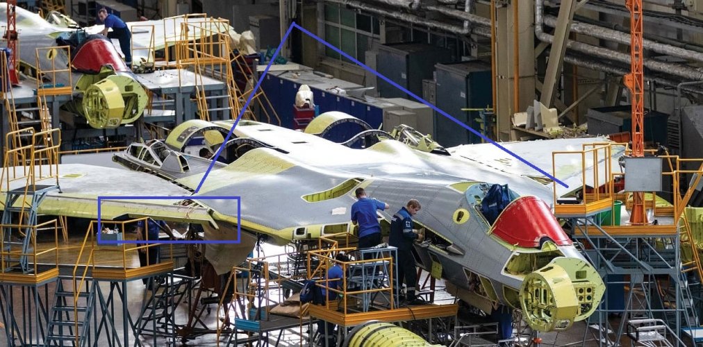
'' A rather extended aperture with a length of up to 10λ can be placed in the wing tip, which will be able to provide the required angular resolution in one plane - in azimuth. ''
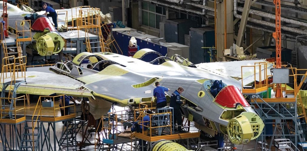
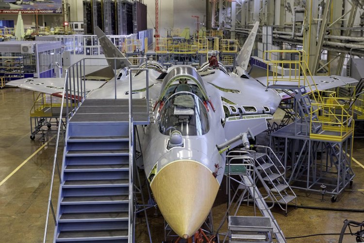
So that kind of antenna could be 240cm in width ( λ=24cm x 10λ ) but instead of that solution ,they made and installed 4 antennas with width of about 160cm in LEVCON's tip and in wing slats tip . There are more technical and tactical possibilities with 4 rather than 2 antennas . As written before, these 4 bigger antennas have two waveguides . One ( upper) for emitting signals when LEVCON's and wing slats are in the lower position and another row ( lower) for emitting signals when LEVCON's and wing slats are in the neutral position.
Advertisement from the MAKS2009
''At the MAKS-2009 air show, at the stand of the Tikhomirov Research Institute of Instrumentation, L-band AESA will also be demonstrated. Designed to fit into the deflectable wing tips of a fighter jet. It is also made on modern hybrid-integral domestic technologies and provides electronic scanning by a beam in a wide sector of angles in azimuth and in a wide frequency band. This locator, like the X-band AESA, was assembled at NIIP, where a unique laboratory testing base was created for this, including anechoic chambers equipped with the latest modern technology.The use of the L-band in air-to-air radar operation is the T-50's primary task of detecting stealth aircraft ''
Then there are some NPP Pulsar articles from 2010/2011 about the modernisation and upgrading of those TRM:
MODERNIZATION OF A POWERFUL L-BAND ON-BOARD AESA MODULE
''The module of the initial development was presented at the Pulsar-2008 conference, and is now being mastered in production. The issue of its modernization is a response to the requirement for a prompt increase in the level of operational characteristics, which is typical of rapidly developing areas of technology.The main goal of the upgrade is to increase the output pulse power level from 400 W to 700 W in a record frequency band of 1 -1.5 GHz in each of the 4 channels of the module. At the same time, the overall and connection characteristics of the module remain unchanged.
The modernization is based on a new generation of integrated assemblies called “power amplifiers” to replace powerful microwave transistors, as well as the development of the principle of volumetric integration.The upgraded module is a transceiver with a noise factor in a given band of no more than 4 dB. A variant of constructive upgrade of the housing is considered in order to improve the technological efficiency of assembly, control and repairability.
In terms of the parameter specific output pulse power per unit of module volume, the obtained result (2 kW/l) exceeds known world achievements.''
ELECTRICAL AND FUNCTIONAL CHARACTERISTICS OF THE UPGRADED MODULE FOR THE L-BAND AIRBORNE AESA
I.V. Korenkov
FSUE NPP Pulsar, Moscow
''The module developed and supplied to the customer is characterized by a high level of output power (400 W per channel), wide bandwidth (1 – 1.5 GHz), and high functional capabilities.The main ones are: high sensitivity in reception mode (noise factor less than 4 dB), the presence of a secondary power source (SPS) with high voltage stabilization rates, multi-level built-in control, ensuring operation in a wide temperature range (from –60°C to +70°C), control of the phase of the received and transmitted signals.During the production and operation of the module, a requirement arose to increase the output power of each channel from 400 to 700 W. At the same time, the customer refused the "antenna equivalent" function.''
All of these info are from the period before test flights with N036L which started from 2013 on the prototype number 055 blue ( 2008-2011). I must find NPP Pulsar articles from 2011/2012 where is mentioned that they increased max output pulse power per channel to almost 1kW.

