New edition of the 'Military acepptance'.
View: https://www.youtube.com/watch?v=eH_tG1MBcwI&t=75s
You are using an out of date browser. It may not display this or other websites correctly.
You should upgrade or use an alternative browser.
You should upgrade or use an alternative browser.
Sukhoi Su-57 flight testing, development & operations [2012-current]
Shaman Harris
ACCESS: Confidential
- Joined
- 26 March 2025
- Messages
- 51
- Reaction score
- 23
Thrust vectoring CAN improve trim drag and fuel burn.But is this the case for canted TVC?
- Joined
- 15 January 2021
- Messages
- 393
- Reaction score
- 1,439
If you move the nozzles symmetrically, you can adjust the trim drag. However, the canted orientation will generate wasted side forces that cancel out, so a bigger thrust penalty for trim drag reduction. Don’t know if it would be a net gain.Thrust vectoring CAN improve trim drag and fuel burn.But is this the case for canted TVC?
I'd say they are even more important. Modern planes rarely, go dogfighting. But improved safety and better take-off influencing every flight and reduce number of accidents.These are often glossed over.
Shaman Harris
ACCESS: Confidential
- Joined
- 26 March 2025
- Messages
- 51
- Reaction score
- 23
I think they are forced to stick with the canted nozzles. The airframe was designed to handle canted nozzles. It will flush with the rest of the aircraft better and get more rcs reduciton with uncanted nozzles .The loss of yaw can kinda be compensated with all moving v tail and "splitting the throttles". This sort of feels like an afterthought to me.
Shaman Harris
ACCESS: Confidential
- Joined
- 26 March 2025
- Messages
- 51
- Reaction score
- 23
Russia is well, large.Having long legs is good
Shaman Harris
ACCESS: Confidential
- Joined
- 26 March 2025
- Messages
- 51
- Reaction score
- 23
Well the first serial su-57 ,a few Y/F-22s and two 737 max have crashes related to FCS. The Japanese claimed the x-2 has a giant beetle RCS (because of US approval). It has exposed tvc metal paddles and the intakes are not planform aligned so it is just PR. The main purpose should be testing their own version of "Self Repairing Flight Control Capability" which seemed to be first researched by the F-15 ACTIVE.I'd say they are even more important. Modern planes rarely, go dogfighting. But improved safety and better take-off influencing every flight and reduce number of accidents.
Shaman Harris
ACCESS: Confidential
- Joined
- 26 March 2025
- Messages
- 51
- Reaction score
- 23
x-2 the plane is a flying test bed ,the atd-x programme had various concepts.
Shaman Harris
ACCESS: Confidential
- Joined
- 26 March 2025
- Messages
- 51
- Reaction score
- 23
The Su-27M was a project from the 80s to maximize the dogfight of the flanker so it got the canted TVC.Su-35 adopted it and eventually Su-57. Su-57 is not a body kit flanker of course but is still a "victim" of it. The weapons bay is derived from the Su-47 and they have to make do what they have.Weapons bay/pylon problems is not unique to Russia. KF-21 will have weapons bay some years later and the only "benefit" of the canted pylons of the super hornet is additonal drag.Using the weapons bay of Su-47 is quite reasonable.
The Su-27M was a project from the 80s to maximize the dogfight of the flanker so it got the canted TVC.Su-35 adopted it and eventually Su-57. Su-57 is not a body kit flanker of course but is still a "victim" of it. The weapons bay is derived from the Su-47 and they have to make do what they have.Weapons bay/pylon problems is not unique to Russia. KF-21 will have weapons bay some years later and the only "benefit" of the canted pylons of the super hornet is additonal drag.Using the weapons bay of Su-47 is quite reasonable.
Only one prototype of the Su-27M got TVC and that was T-10M-11 number 711, widely known as Su-37. After that ,same solution for the TVC was applied on Su-30MKA,MKI,MKM ( AL-31FP) ,then Su-35S ( AL-41F-1S) and Su-30SM/SM2 (AL-31FP/AL-41F-1S).
Of course ,AL-41F-1 and newer AL-51F for the Su-57 have that same solution.
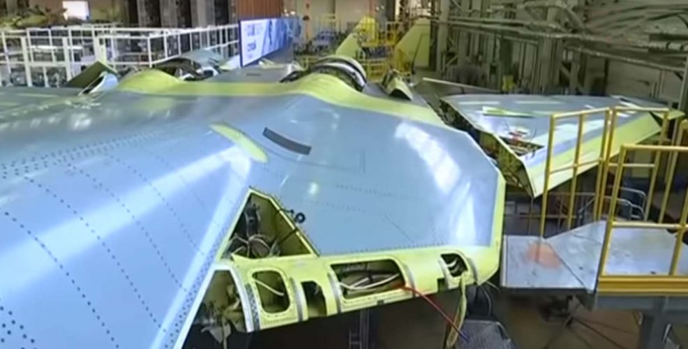
When we talk about that Su-47 called Berkut ( S-37), it was technological demonstrator for the stealth technologies and for the testing of the composite materials especially composites as structural materials for the wings.
Citation :
''In 2006-2007, after the weapon compartment was modernized, the aircraft was involved in the program to create the T-50 fighter project (later Su-57). The goal was to test the compartment doors and internal equipment for operability under real flight conditions. The information was actively used in the final stages of creating the weapon compartments of the T-50 fighter.''
''Work on the wing for the Berkut subsequently made it possible to use composites from Obninsk in the creation of the fifth-generation Su-57 fighter and the MS-21 airliner.''
On the photos we can see the legacy from the Su-47, the composites ( grayish blue color) and the weapon compartment doors.
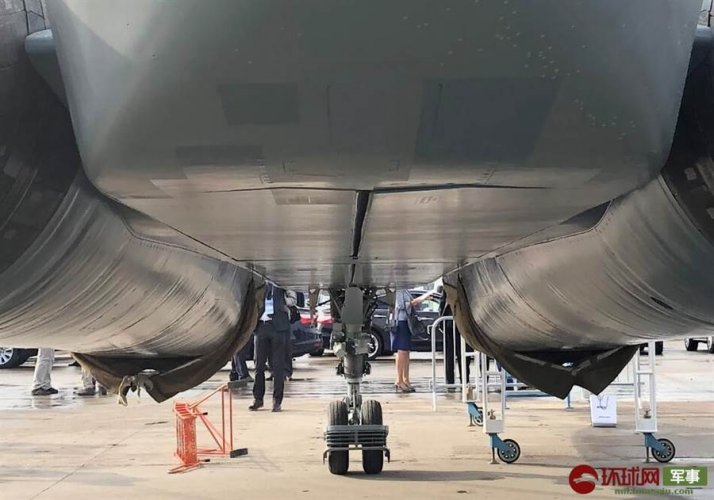
can someone explain why canted nozzles are not as good as vertical nozzles? Why do they create drag I never really understood that discussion? If I remember correctly the su-35/37 it was numbered 117 and it could move its nozzles up and down but not canted. Then when the su-30 was introduced that’s when the v pattern TVC was used.
- Joined
- 15 January 2021
- Messages
- 393
- Reaction score
- 1,439
What’s good about the canted nozzles is that when moved asymmetrically, they can generate yaw and rolling moments that can help maneuvering those planes without the complication of full 3D vectoring.
The downside is when they are actuated symmetrically for pitch vectoring, more thrust is wasted generating side loads that are cancelled out.
Plus, the new Su-57 2D flat nozzle just look wrong, and are unlikely to make a large contribution to overall stealth of the aircraft due to adding additional flat surfaces not aligned with the existing airframe edge alignment. It remains to be seen if there will be any significant improvement in observability inside the AB cavity.
Shaman Harris
ACCESS: Confidential
- Joined
- 26 March 2025
- Messages
- 51
- Reaction score
- 23
It is believed there is some kind of "blocker"What’s good about the canted nozzles is that when moved asymmetrically, they can generate yaw and rolling moments that can help maneuvering those planes without the complication of full 3D vectoring.
The downside is when they are actuated symmetrically for pitch vectoring, more thrust is wasted generating side loads that are cancelled out.
Plus, the new Su-57 2D flat nozzle just look wrong, and are unlikely to make a large contribution to overall stealth of the aircraft due to adding additional flat surfaces not aligned with the existing airframe edge alignment. It remains to be seen if there will be any significant improvement in observability inside the AB cavity.
Shaman Harris
ACCESS: Confidential
- Joined
- 26 March 2025
- Messages
- 51
- Reaction score
- 23

Su-57 Felon’s Two-Dimensional Thrust-Vectoring Engine Nozzle Breaks Cover
The flattened exhaust nozzle installed at an angle is planned to reduce the signature of advanced versions of the Su-57. The novel flattened exhaust nozzle is planned to reduce the radar signature of advanced versions of the Su-57 Felon fighter.
What’s good about the canted nozzles is that when moved asymmetrically, they can generate yaw and rolling moments that can help maneuvering those planes without the complication of full 3D vectoring.
The downside is when they are actuated symmetrically for pitch vectoring, more thrust is wasted generating side loads that are cancelled out.
Plus, the new Su-57 2D flat nozzle just look wrong, and are unlikely to make a large contribution to overall stealth of the aircraft due to adding additional flat surfaces not aligned with the existing airframe edge alignment. It remains to be seen if there will be any significant improvement in observability inside the AB cavity.
It's a 3D flat nozzle. M7 explained some details from 6:55 ( 2D vs 3D) ....
Apart from what was M7 analysed ,Mikhail Strelets said this :
‘'In essence, the flat nozzle complements the existing aerodynamic controls by allowing the creation of moments in three planes and thus pitch, roll and yaw control. And since the nozzle installation angle is preserved with axisymmetric, all the possibilities of super manoeuvring the aircraft are also preserved,’ explained Mikhail Strelets.''
''По словам главного конструктора, плоское сопло также обеспечивает малую заметность в радиолокационном диапазоне за счет характерной формы и может использоваться в широком диапазоне высот и скоростей полета самолета. Оно позволяет создавать управляющие моменты в трех плоскостях, сохраняя все возможности по сверхманевренности самолета.''
Last edited:
Shaman Harris
ACCESS: Confidential
- Joined
- 26 March 2025
- Messages
- 51
- Reaction score
- 23
"creation of moments " ,it is still canted 2d
Shaman Harris
ACCESS: Confidential
- Joined
- 26 March 2025
- Messages
- 51
- Reaction score
- 23
Shaman Harris
ACCESS: Confidential
- Joined
- 26 March 2025
- Messages
- 51
- Reaction score
- 23
Should someone open a thread dedicated to "Self Repairing Flight Control"?
Should someone open a thread dedicated to "Self Repairing Flight Control"?
Sounds like a good idea.
Null
ACCESS: Confidential
- Joined
- 16 December 2024
- Messages
- 74
- Reaction score
- 101
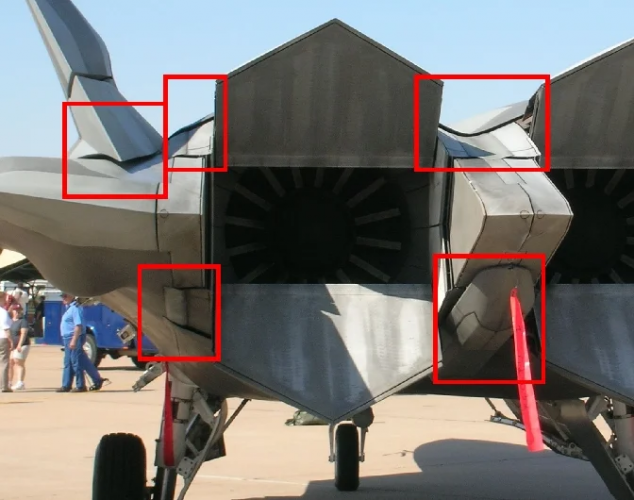
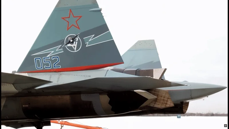
So which has better RCS treatment?What’s good about the canted nozzles is that when moved asymmetrically, they can generate yaw and rolling moments that can help maneuvering those planes without the complication of full 3D vectoring.
The downside is when they are actuated symmetrically for pitch vectoring, more thrust is wasted generating side loads that are cancelled out.
Plus, the new Su-57 2D flat nozzle just look wrong, and are unlikely to make a large contribution to overall stealth of the aircraft due to adding additional flat surfaces not aligned with the existing airframe edge alignment. It remains to be seen if there will be any significant improvement in observability inside the AB cavity.
Shaman Harris
ACCESS: Confidential
- Joined
- 26 March 2025
- Messages
- 51
- Reaction score
- 23
can't really make a plane "seamless" and polished
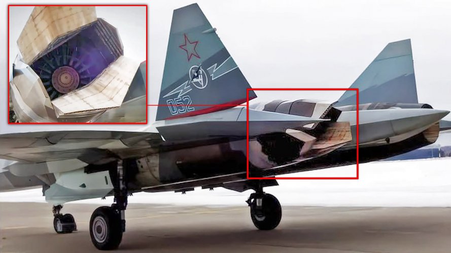
It is believed there is some kind of "blocker"
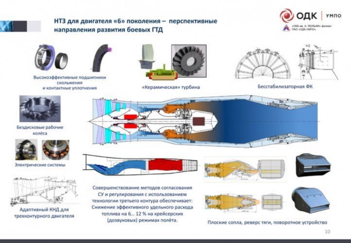
If you mean on this what we can see on the upper left mini-pic ,it is the AB chamber without stabilizer.
"creation of moments " ,it is still canted 2d
OK then ,now let us see what can do the '3D-nozzles' of the AL-41F-1S (also of AL-31FP and AL-41F1/-51F) .
On the upper left pic both nozzles (gas stream) are directed upwards, on the upper right pic, left nozzle is directed upwards,right is directed downwards.On the lower left pic we can see the vice-versa situation.
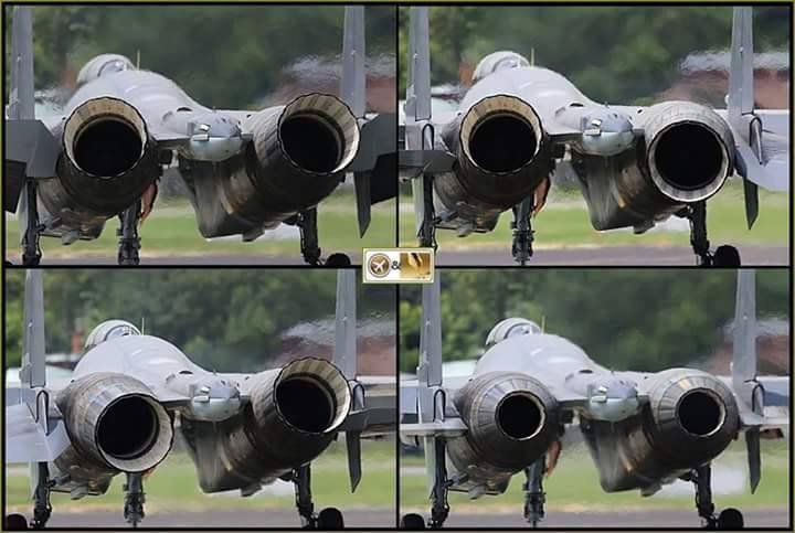
All of this can be done with that new flat nozzle.That's why this new flat nozzle is placed in this angled position.
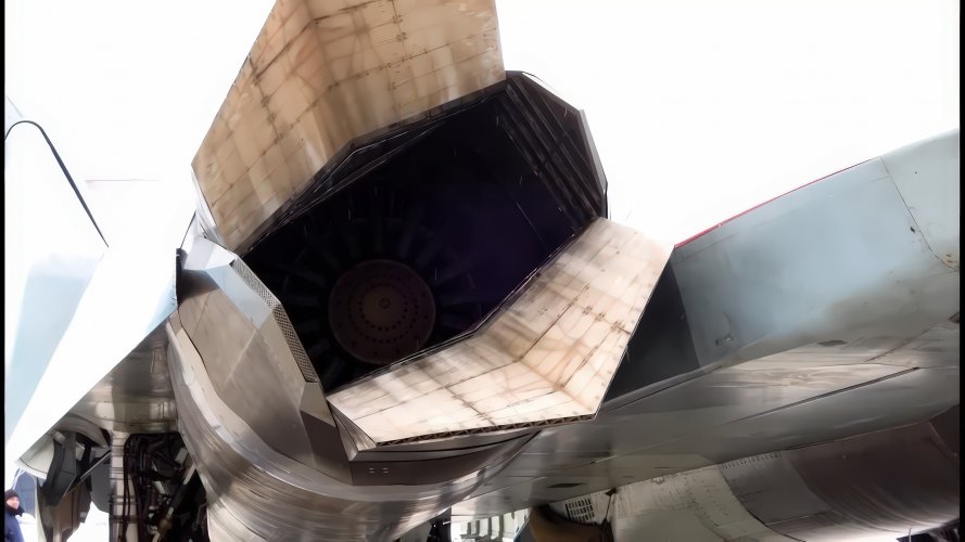
So on PW F119 we have the flat nozzles that can be directed only straight upwards and downwards.This new flat nozzle as we can see can be directed upwards/downwards but with a beveled angle as in the mentioned engines.
Patent doc. of the flat nozzle from 2017.
Плоское сопло турбореактивного авиационного двигателя
Плоское сопло турбореактивного авиационного двигателя
RU2674232C1 - Плоское сопло турбореактивного авиационного двигателя - Google Patents
ÐзобÑеÑение оÑноÑиÑÑÑ Ðº облаÑÑи авиаÑионного двигаÑелеÑÑÑоениÑ, а именно к конÑÑÑÑкÑии плоÑÐºÐ¸Ñ Ñопел ÑÑÑбоÑеакÑивнÑÑ Ð´Ð²Ð¸Ð³Ð°Ñелей. ÐлоÑкое Ñопло ÑодеÑÐ¶Ð¸Ñ Ð¿Ð¾ÑледоваÑелÑно...
patents.google.com
Shaman Harris
ACCESS: Confidential
- Joined
- 26 March 2025
- Messages
- 51
- Reaction score
- 23
LMFS
ACCESS: Top Secret
- Joined
- 19 March 2019
- Messages
- 533
- Reaction score
- 880
That is just a flawed animation made by someone that does not understand the planeIt's a 3D flat nozzle. M7 explained some details from 6:55 ( 2D vs 3D) ....
In fact, that was a candidate for the second stage engine ''Izdeliye 30'' called 'Yeniseisk-B'.
Some info from 2010,source was VPK :
''Условиями конкурса на разработку двигателя второго этапа для ПАК ФА, по словам Юрия Елисеева, предусматривалось конструирование двух прототипов: "Енисейск-А" - "Сатурну" и "Енисейск-Б" - "Салюту". Первый этап состязания, предполагавший создание отдельных деталей, завершился в ноябре 2008 года; второй, в ходе которого участники должны были представить демонстраторы узлов, финишировал в июне 2009-го. "Что касается "Салюта", - заявил гендиректор этого предприятия, - то имеется заключение комиссии, состоящей из представителей Минобороны, ЦИАМ и ЦНИИ-30 МО, гласящее, что работа выполнена в полном объеме на уровне не ниже мирового, результаты рекомендуются для использования при проектировании двигателя пятого поколения. Что касается "Сатурна", то им, насколько я знаю, второй этап пока не выполнен". К третьему этапу, объявление которого откладывается с третьего квартала прошлого года, в КБ "Салюта" создан аванпроект двигателя пятого поколения, который согласно заключению соответствует техническому заданию.
Как заявил Юрий Елисеев, "у меня никогда не было сомнений, что двигатель пятого поколения может быть создан только совместными усилиями. Финансирование должно идти через ОДК. ''
''According to Yuri Eliseev, the conditions of the competition for the development of the second stage engine for the PAK FA included the construction of two prototypes: "Yeniseisk-A" for "Saturn" and "Yeniseisk-B" for "Salyut". The first stage of the competition, which involved the creation of individual parts, was completed in November 2008; second, in which participants had to present demonstrators of components, finished in June 2009.
"As for Salyut," said the general director of this enterprise, "there is a conclusion from a commission consisting of representatives of the Ministry of Defense, TsIAM and TsNII-30 MO, stating that the work has been completed in full at a level no lower than the world level, the results are recommended for use in the design of a fifth-generation engine.
As for Saturn, as far as I know, they have not yet completed the second stage." For the third stage, the announcement of which has been postponed since the third quarter of last year, the Salyut Design Bureau has created a preliminary design for a fifth-generation engine, which, according to the conclusion, corresponds to the technical specifications.
As Yuri Eliseev stated, "I never had any doubts that the fifth generation engine can only be created through joint efforts. Financing should go through UEC.''
Двухконтурная интеграция // АвиаПорт.Новости
Началось объединение активов для создания авиадвигателя пятого поколения
That is just a flawed animation made by someone that does not understand the plane
The animation itself was of course wrong.
Galaxy
ACCESS: Restricted
- Joined
- 14 December 2024
- Messages
- 39
- Reaction score
- 60
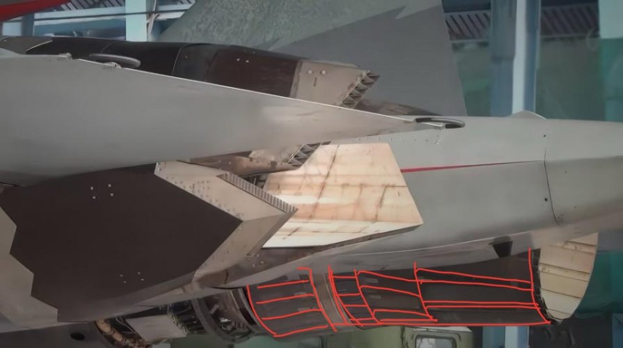
Your red marks clearly show that you don't understand what "RCS treatment" means.
So educate him instead of asking rhetorical questions. What is “RCS treatment”? The science says RCS can only be reduced, nothing can 100% be ‘treated’ in order to completely illuminate RCS. Any discontinuity, gap or seam creates interference with electromagnetic energy. Ideally designers want zero discontinuity with a surface that is perfectly smooth. However, in the real world that is not possible due to flight control surfaces, assess panels, auxiliary ports, bays, ect. There is no such concept of being invisible to radar, the best designers can do incorporate techniques such as faceting, edge alignment, RAM, ect in order to reduce the RCS. At certain distances and aspect angles some aircraft may be more or less invisible to certain radars operating in certain frequencies but once an aircraft gets closer to the source of illumination and the frequency and aspect angles are ideal then the aircraft may be visible.
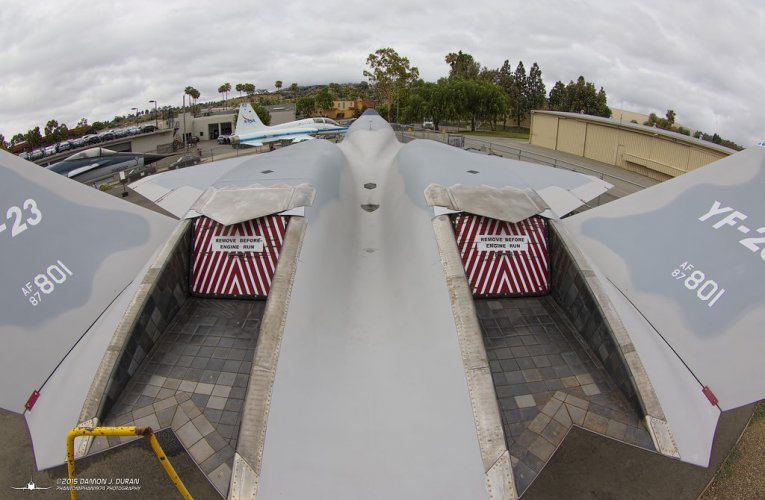
There are no such thing as gaps or seems that are stealth, that is a contradiction. The best engineers can do is redirect the RCS away or try to mask it by using RAM or trying to shield it behind other structures such as vertical stabilizers. Everything is a design compromise, the YF-22 had the TVC engines and horizontal stabilizers but payed a penalty in stealth compared to the YF-23.

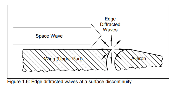
Yes the F-22 has serrated seams around the engine to minimize RCS and the effects of edge diffraction but it will never eliminate it completely and from every aspect angle. Moreover there are 90 degree corner reflectors. The reason the YF-23 had a lower RCS compared to the YF-22 was precisely because it omitted the horizontal stabilizers to eliminate those additional corner reflectors and simplified the engines. There is nearly no seams anywhere on the WF-23 as it’s a fixed engine recessed into the rear fuselage.
Rant mode on.
...rear array(for 360 coverage and more array estate than dedicated NGJs), side L arrays(~240 coverage), spherical optics in two bands(UV, mwIR), dual-band frontal irst(mw/lwir), spherical DIRCM, full integration (system design, data fusion, cross use for different subsystems) for everything above, active countermeasures as designed, actual flight and stol performance worthy of its generation, comprehendive weapon suite working earlier than 10 years after IOC, and LO. Helmet was also always there, too, the difference is you now got to see it in production form. As are other normal generation features no one bothers to mention.
A lot of things you've missed. All of them designed in since 2001, well known for more than a decade. All much more important for the aircraft than flat nozzles.
It makes your final assessment questionable, as you were clearly gauging some other aircraft.
Absolute majority of people coming to this thread with their opinions - don't even have wiki level knowledge on the subject(or do, and come somewhat overenthusiastic). Then it takes several pages of amazing discoveries.
It's one thing when someone comes to ask, but for judgements normally it's polite to at least make some research first?
And it happens over and over and over.
What’s good about the canted nozzles is that when moved asymmetrically, they can generate yaw and rolling moments that can help maneuvering those planes without the complication of full 3D vectoring.
The downside is when they are actuated symmetrically for pitch vectoring, more thrust is wasted generating side loads that are cancelled out.
Plus, the new Su-57 2D flat nozzle just look wrong, and are unlikely to make a large contribution to overall stealth of the aircraft due to adding additional flat surfaces not aligned with the existing airframe edge alignment. It remains to be seen if there will be any significant improvement in observability inside the AB cavity.
So flat smooth nozzles with less seams and discontinuities do almost nothing for RCS compared to round nozzles that have multiple chambers and dozens moving parts, bolts, gaps and no edge alignment?
Even if we are talking about the round “stealth” nozzles they still have the variable nozzle flaps that create some corner reflectors and at full deflection there are gaps between the flaps…there is simply no way that something like that has the same or lower RCS compared to a flat nozzle that emits all those flaps and gaps and moving parts. Moreover, the flat nozzles provide superior IR signature. With flat canted nozzles the engineers also eliminated the phenomenon of ‘creeping waves’ and also eliminated a rough cylinder and replaced it with a mostly smooth canted surface. The RCS improvement should be significant.
A rough illustration of what im talking about:
Isn't this the reason why the Su-57's engines are angled slightly outwards? I'd guess the Su-57 cruises at a slight positive AoA, like the Flankers do then the TVC would allow to have the engines point straight backwards in cruising flight.If you move the nozzles symmetrically, you can adjust the trim drag. However, the canted orientation will generate wasted side forces that cancel out, so a bigger thrust penalty for trim drag reduction. Don’t know if it would be a net gain.
Btw, how common is it for jets to cruise at positive AoA, particularly stealth ones? I'd assume this increases the RCS somewhat.
LMFS
ACCESS: Top Secret
- Joined
- 19 March 2019
- Messages
- 533
- Reaction score
- 880
Like 100% common, otherwise they would fall from the sky.Btw, how common is it for jets to cruise at positive AoA, particularly stealth ones? I'd assume this increases the RCS somewhat.
Trimming is another question. There TVC can be more efficient than aerodynamic surfaces, but specifically when the CoL transitions backwards in supersonic flight, the contribution of deflected TVC would be negative lift, so it is also not ideal. Maybe the LEVCONS are the best option there, always considering that the unstable design should allow to reduce the TVC deflection to a minimum in supersonic flight.
Pitching the aircraft isn't the only way to generate lift - there's vortex lift and the aerodynamic shape of the wings themselves.
I just realized that the engines are moving on a wrong axis for the scheme I proposed to work - outward angled engines with outward facing axis of TVC rotation means that at positive AoA, you need to rotate the nozzles down, not up to get the thrust vector to line up with the centerline of the aircraft. This also doesn't help with a backwards center of lift, as that assumes that the aircraft has a natural tendency to pitch down - angling the thrust downwards does the opposite of trimming.
Afaik Levcons aren't really pitch control devices - aerodynamically speaking they roughly change the virtual 'angle of attack' of the wings in terms of vortex generation, so they change the amount of lift the wings generate, not the location at which the forces appear. I'd say they help getting rid of induced drag instead of trim drag - though they can probably help with reducing the counterbalancing forces the tails or the TVC has to generate - that's why I asked the AoA question - upwards deflected Levcons have a similar lifting effect to pitching the aircraft itself.
Edit: Now that I think about it, keeping the flow attached might be more useful than having vortex lift, so the Su-57 might actually be flying at an AoA with its levcons slightly shifter downwards.
Last edited:
Shaman Harris
ACCESS: Confidential
- Joined
- 26 March 2025
- Messages
- 51
- Reaction score
- 23
Serious pylon problems on super hornet
Those LEVCON's are something really special and unique aerodynamic feature of the Su-57 as those LERX's are for the FFF ( Flanker Family Fighters).

Materials of the Polish and Chinese authors....
'LEVCON vs LERX'
''Amid actuated devices such as leading-edge flaps, trailing-edge flaps, or slats a new type of device has been trending in recent years. This device is called the leading-edge vortex controller (LEVCON), and it is a continuation of an already existing and widely used aerodynamic solution called the leading-edge root extension (LERX). In comparison, LEVCON is designed to operate similarly to LERX, with its aim being to generate lift-augmenting vortices, i.e., vortex lift, at high angles of attack. While LERX is a fixed aerodynamic component of the aircraft, LEVCONs are actuated devices, which improve their performance in areas beyond high-angle-of-attack scenarios.
In fact, this aerodynamic solution might have more significance in classified research, as it is currently implemented in only one operational aircraft type: the Russian Sukhoi Su-57.''

 www.mdpi.com
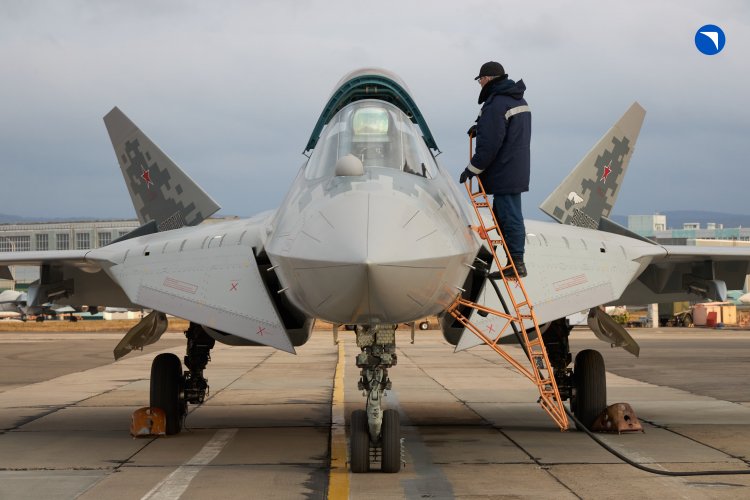
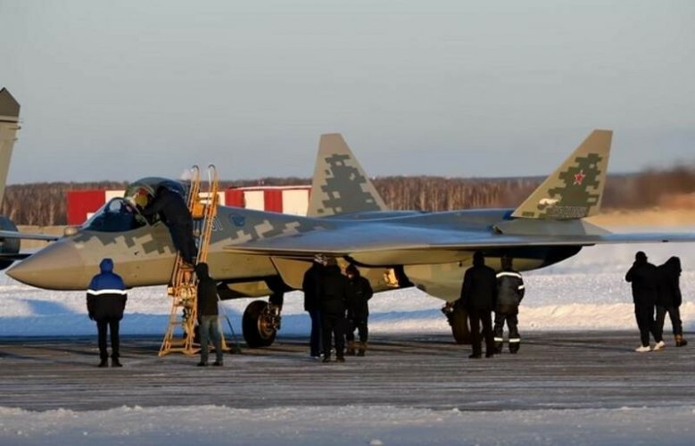
Rare photo where we can see LEVCON with little bit of upward deflection.

One older description....

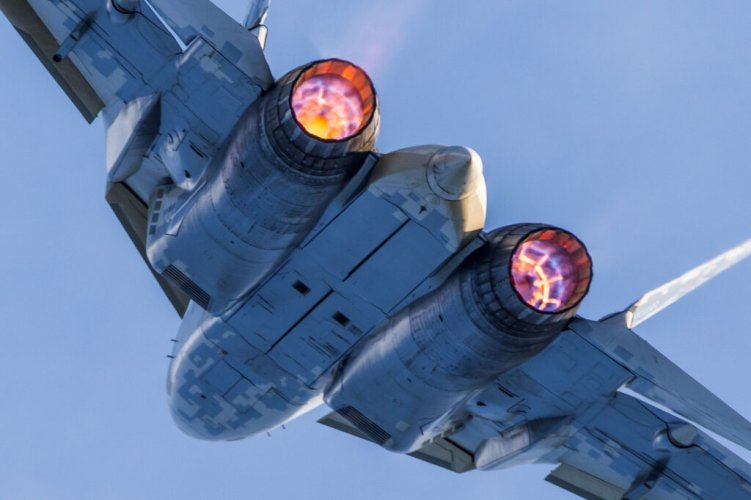
Two amazing pics ,engines on AB mode with LEVCON's in downward positions.Upper pic is even more interest because of the nozzles deflections.


Materials of the Polish and Chinese authors....
'LEVCON vs LERX'
''Amid actuated devices such as leading-edge flaps, trailing-edge flaps, or slats a new type of device has been trending in recent years. This device is called the leading-edge vortex controller (LEVCON), and it is a continuation of an already existing and widely used aerodynamic solution called the leading-edge root extension (LERX). In comparison, LEVCON is designed to operate similarly to LERX, with its aim being to generate lift-augmenting vortices, i.e., vortex lift, at high angles of attack. While LERX is a fixed aerodynamic component of the aircraft, LEVCONs are actuated devices, which improve their performance in areas beyond high-angle-of-attack scenarios.
In fact, this aerodynamic solution might have more significance in classified research, as it is currently implemented in only one operational aircraft type: the Russian Sukhoi Su-57.''
Leading-Edge Vortex Controller (LEVCON) Influence on the Aerodynamic Characteristics of a Modern Fighter Jet

Leading-Edge Vortex Controller (LEVCON) Influence on the Aerodynamic Characteristics of a Modern Fighter Jet
The purpose of this paper is to assess the influence of a novel type of vortex creation device called the leading-edge vortex controller (LEVCON) on the aerodynamic characteristics of a fighter jet. LEVCON has become a trending term in modern military aircraft in recent years and is a...
A Numerical Study on the Aerodynamic Characteristics of Leading-Edge Vortex Controllers on a Fighter Pertinent to Su-57
Rare photo where we can see LEVCON with little bit of upward deflection.
One older description....

Two amazing pics ,engines on AB mode with LEVCON's in downward positions.Upper pic is even more interest because of the nozzles deflections.
Manuducati
ACCESS: Secret
- Joined
- 25 November 2020
- Messages
- 328
- Reaction score
- 1,056
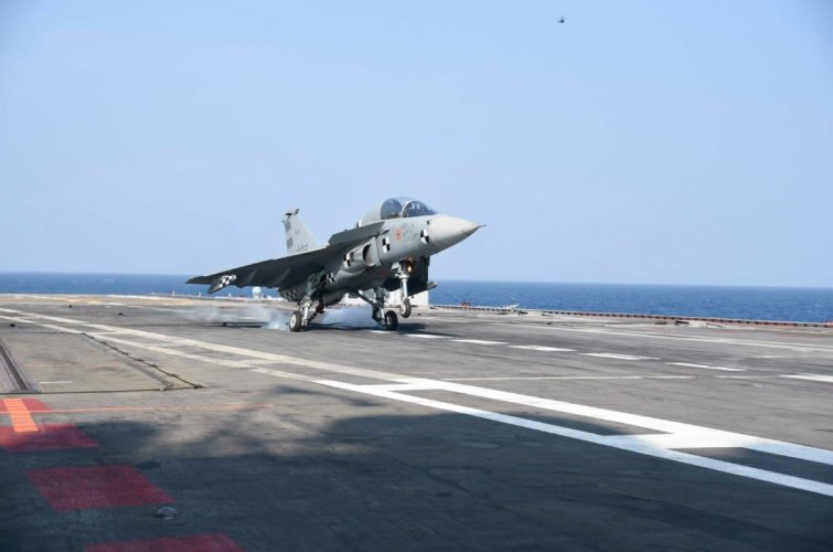
Every time I hear or read that the LEVCON concept is unique to the Su-57, I can't help...
(Plus a handful of unflown Northrop MRF studies.)View attachment 765032
Is that the Tejas?
Rhinocrates
ACCESS: Top Secret
- Joined
- 26 September 2006
- Messages
- 3,019
- Reaction score
- 7,659
OK then ,now let us see what can do the '3D-nozzles' of the AL-41F-1S (also of AL-31FP and AL-41F1/-51F) .
View attachment 764910
The aeronautical equivalent of twerking.
Manuducati
ACCESS: Secret
- Joined
- 25 November 2020
- Messages
- 328
- Reaction score
- 1,056
Is that the Tejas?
Yes, the naval Tejas, aka Navy LCA or LCA (N). Its development was halted in favor of the TEDBF, with the Rafale Marine being purchased in the meantime.
Shaman Harris
ACCESS: Confidential
- Joined
- 26 March 2025
- Messages
- 51
- Reaction score
- 23
very long development cycle,likely some after thoughtEvery time I hear or read that the LEVCON concept is unique to the Su-57, I can't help...
(Plus a handful of unflown Northrop MRF studies.)View attachment 765032
Stormingart
ACCESS: Restricted
- Joined
- 14 November 2024
- Messages
- 12
- Reaction score
- 14
Similar threads
-
Sukhoi Su-57 / T-50 / PAK FA first flight - pictures, videos and analysis [2010]
- Started by flateric
- Replies: 872
-
Sukhoi Su-57 / T-50 / PAK FA - flight testing and development Part I [2010-2012]
- Started by Matej
- Replies: 760
-
Sukhoi PAK FA news and speculation (T-50, I-21) Part I [2006-2008]
- Started by overscan (PaulMM)
- Replies: 455
-
Sukhoi's T-58M - an Su-24-based interceptor
- Started by overscan (PaulMM)
- Replies: 1
-
Article Related to Some of Russian Air Launched Missile Programme
- Started by ocay
- Replies: 0

