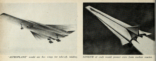
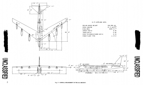
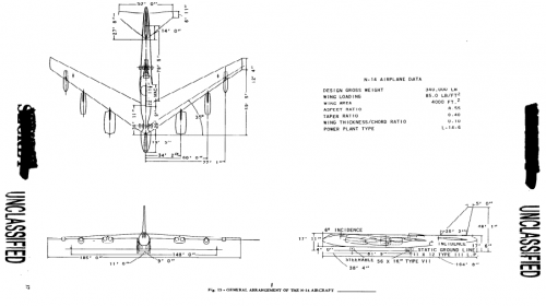
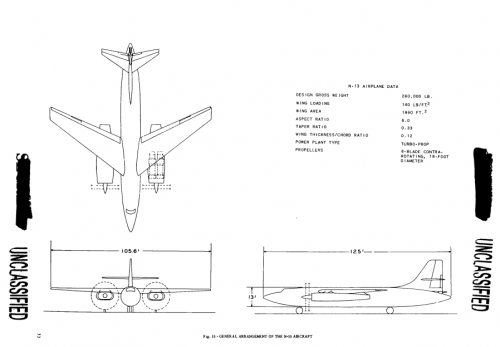
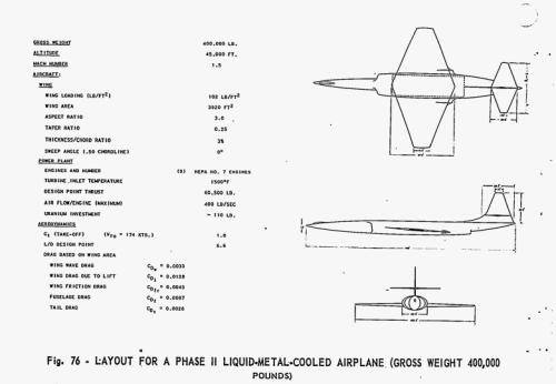
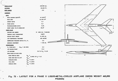
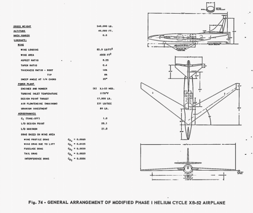
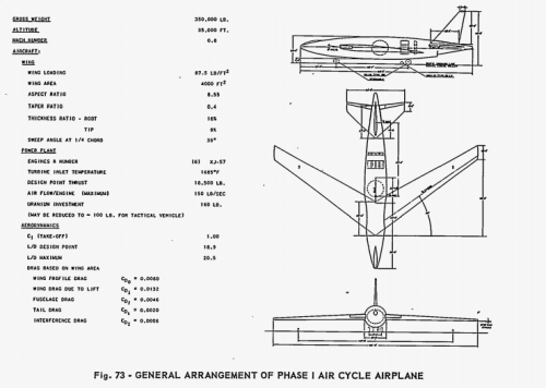
From Kryl'ya Rodine 4/2002,


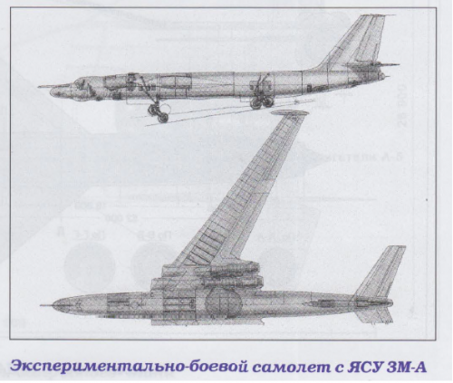
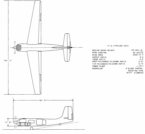
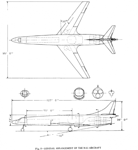
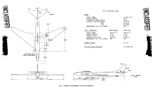
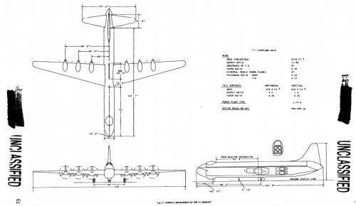
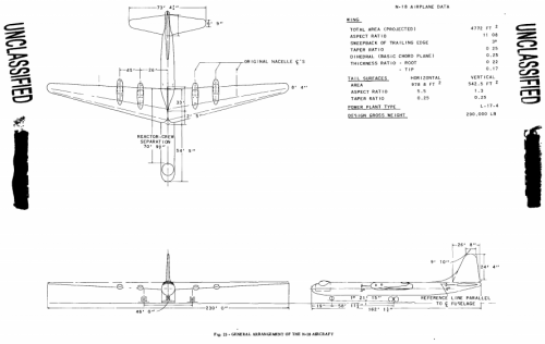
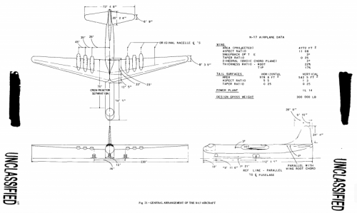
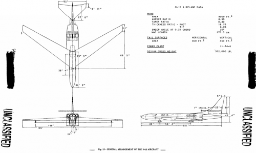
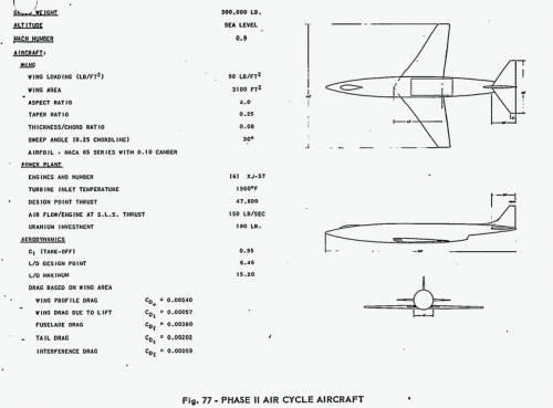
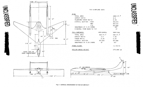
here is a 3-view to Convair Nuclear powered aircraft.
 

Attachments

  • Convair.png
    Convair.png
    69.9 KB · Views: 228
toura said:
HI ALL
From "Minidocavia" alain pelletier
Who know more ?


My dear Toura,


is that your question,a more info about Model-201 or something else ?.
 
My dear Hesham.

My question is :
"Could someone give me more details on this plane"
Have a nice time
PAUL
 
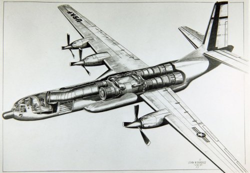
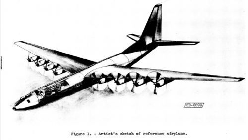
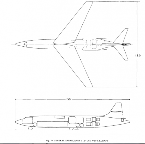
Here is a drawing that was simply identified as "Atomic engine transport". It appears to be a C-133 with the "atomic" engine mounted in the fuselage hold. Also note it only has 3 propeller driven engines, don't know if this was a mistake on the part of the artist. San Diego ASM has more of the artists paintings in their online archives. From looking at the photos it appears he may have worked for General Electric. Below is a link to this gallery. Don't know if was an actual project but thought I'd put it out there for people to see.


Attachments

  • Atomic engine transport.jpg
    Atomic engine transport.jpg
    242.6 KB · Views: 268
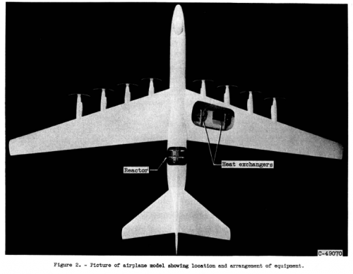
This concept has been discussed before. It wasn't a transport, as such, but an idea for a nuclear turbojet test aircraft. The engine shown here has one reactor feeding two separate turbojets; in this concept, only the starboard turbojet would be "live," with its own inlet and exhaust.

I suspect the lack of an inboard engine on the port wing is a "deleted for clarity" issue.
 
From kryl'ya Rodine 9-10/2013,


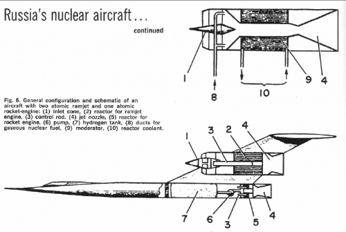
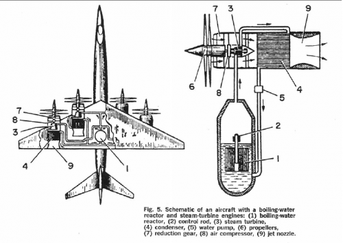
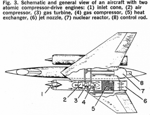
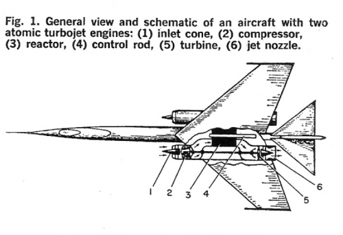
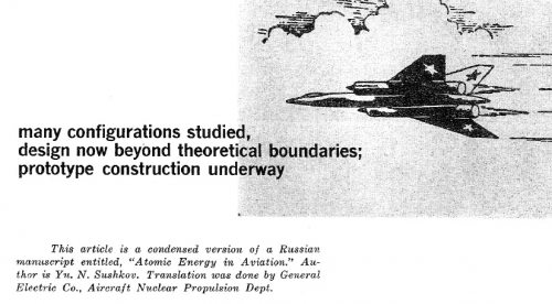
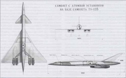
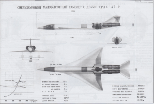
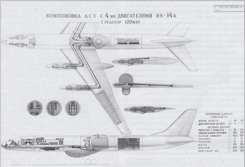
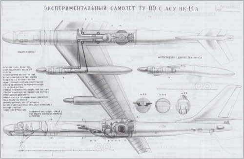
here is some Russian nuclear powered aircraft and projects.
 

Attachments

  • 7.png
    7.png
    395.5 KB · Views: 237
  • 6.png
    6.png
    503.7 KB · Views: 237
  • 5.png
    5.png
    524.9 KB · Views: 237
  • 4.png
    4.png
    625.4 KB · Views: 226
  • 3.png
    3.png
    580.6 KB · Views: 233
  • 2.png
    2.png
    478.8 KB · Views: 238
  • 1.png
    1.png
    465.9 KB · Views: 210
And;
 

Attachments

  • 8.png
    8.png
    663.3 KB · Views: 268
  • 9.png
    9.png
    674 KB · Views: 304
Very nice stuff,thanks a lot hesham,but I'm a bit curious about the image number 8,is it a bomber,fighter,or an unmanned aircraft?
 
pedrospe said:
Very nice stuff,thanks a lot hesham,but I'm a bit curious about the image number 8,is it a bomber,fighter,or an unmanned aircraft?


Hi Pedro,


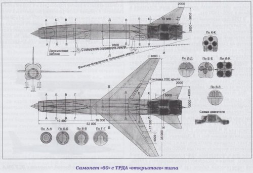
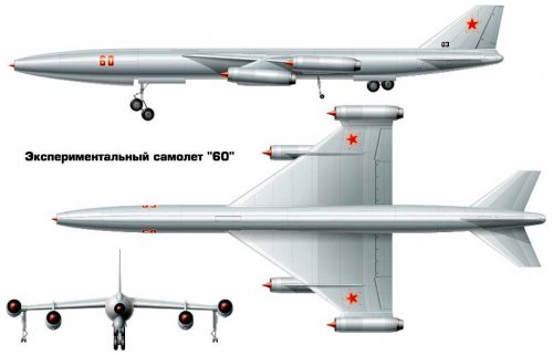
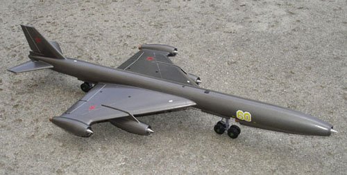
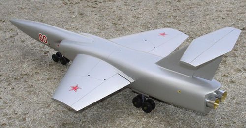
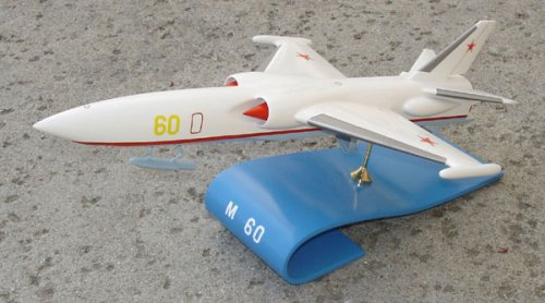
it was Myasishchev M-60 pilotless strategic bomber.
 
Hi,


here is a nuclear powered aircraft,maybe just a hypothetical one.


http://coollib.com/b/158254/read
 

Attachments

  • i_079 (1).jpg
    i_079 (1).jpg
    19.8 KB · Views: 153
My dear Granit,


I think this aircraft differs a little from Myasishchev M-60,it has engines mounted above
the fuselage and T-tail.
 
hesham said:
My dear Granit,


I think this aircraft differs a little from Myasishchev M-60,it has engines mounted above
the fuselage and T-tail.

The text on your link says it is about the M-60. Picture looks like an artistic representation.
 
OK my dear Granit,


we can say early artist drawing to it,with small minor different.
 
Hi,


https://archive.org/stream/missilesrockets6196unse#page/n705/mode/2up
 

Attachments

  • N-1.png
    N-1.png
    1,003.3 KB · Views: 164
  • N-2.png
    N-2.png
    666 KB · Views: 192
Great find my dear Moin1900,


and we can put them here.
 

Attachments

  • 15.png
    15.png
    101.8 KB · Views: 215
  • 14.png
    14.png
    68.6 KB · Views: 199
  • 13.png
    13.png
    66.8 KB · Views: 196
  • 12.png
    12.png
    45.3 KB · Views: 189
  • 11.png
    11.png
    35.2 KB · Views: 164
  • 10.png
    10.png
    31.7 KB · Views: 179
  • 9.png
    9.png
    55.1 KB · Views: 194
  • 8.png
    8.png
    49.1 KB · Views: 203
And;
 

Attachments

  • T-1.png
    T-1.png
    97.8 KB · Views: 161
  • 18.png
    18.png
    74.5 KB · Views: 165
  • 17.png
    17.png
    75.1 KB · Views: 168
  • 16.png
    16.png
    68.3 KB · Views: 140
Also;
 

Attachments

  • V.png
    V.png
    95 KB · Views: 127
  • IV.png
    IV.png
    69.1 KB · Views: 136
  • III.png
    III.png
    87.4 KB · Views: 136
  • II.png
    II.png
    107.8 KB · Views: 123
  • I.png
    I.png
    98.4 KB · Views: 121
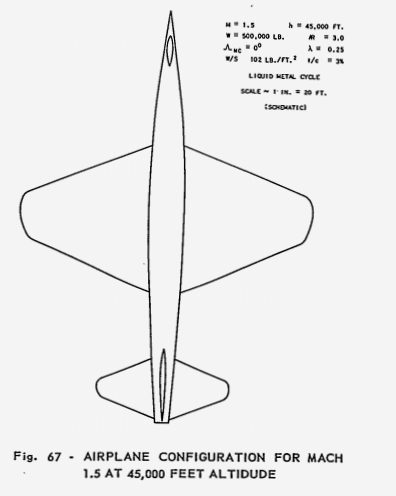
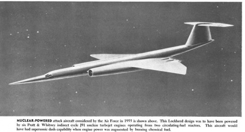
  • Lockheed.png
    Lockheed.png
    75.1 KB · Views: 126
  • 1.png
    1.png
    43.8 KB · Views: 105
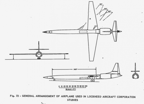
Finally;
 

Attachments

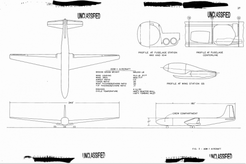
  • ASW-1.png
    ASW-1.png
    69 KB · Views: 148
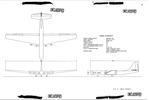
  • ASW-2.png
    ASW-2.png
    56.5 KB · Views: 177
Hi,

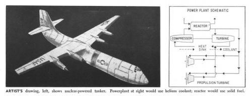
here is a Nuclear-Powered Tanker aircraft.

http://archive.aviationweek.com/image/spread/19580310/30/2
 

Attachments

  • 1.png
    1.png
    104.3 KB · Views: 214
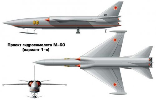
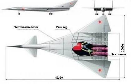
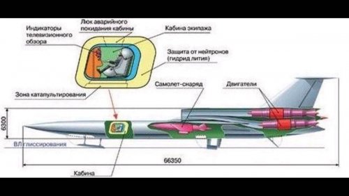
Hi! Myasishcchev M-60 nuclear bomber project.
http://testpilot.ru/russia/myasishchev/m/60/m60.htm

https://topwar.ru/77826-m-60-atomnyy-samolet-vm-myasischeva.html

https://ru.wikipedia.org/wiki/
"M-60
Originally, the designers saw the task of equipping m-50 special Motors Chief Designer a. m. Lyulka. But to the year 1956, it became clear that these engines have a number of problems: it was required to protect the crew from a large number of radiation, maintenance was supposed to occur remotely, strongly zagrjaznjalas' the environment Wednesday.
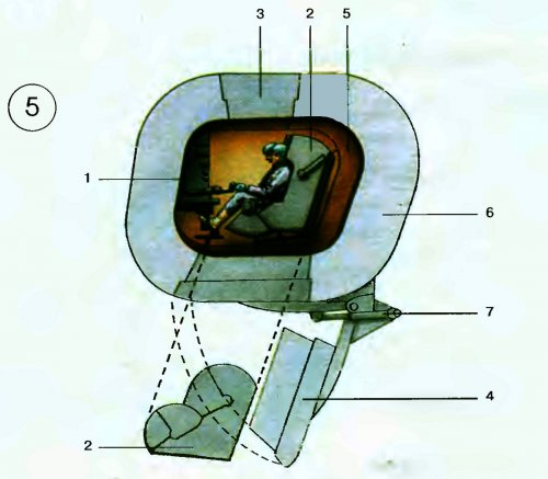
To protect the crew anticipated ispol'zovalat' dead lead capsule weighing approximately 60 tons. In the capsule would have maintained a positive pressure and Visual survey used television, radar screens and periscopes. Control of the plane partially fall on automatics. It was later invited to abandon altogether the crew as the plane could take off, climb, attack the target and return, but the idea was rejected.
For service of such aircraft needed special complexes. Required runway with a thickness of at least 0.5 m Engines were installed on the aircraft would automatically, immediately before the flight. Filling, delivery crew, suspension arms and so too should have been be automated because of the high radiation background."
"M-60 m
Due to the complexity of such land seaplane developed in parallel systems, m-60 m. All in all it was everything the same m-60, only the best engines raised above the ground. For take-off has been used a complex system of retractable underwater wings and gidrolyzh. These aircraft can be based not only in the southern latitudes of the USSR, but also in the North. At that time already possible to maintain such bases in unfrozen."
 

Attachments

  • Open system nuclear jet engine.jpg
    Open system nuclear jet engine.jpg
    22.4 KB · Views: 168
  • 309696_800.jpg
    309696_800.jpg
    102.4 KB · Views: 147
  • m60-3_3.jpg
    m60-3_3.jpg
    36.7 KB · Views: 126
  • m60-1v_3.jpg
    m60-1v_3.jpg
    35.8 KB · Views: 118
  • m60_3.jpg
    m60_3.jpg
    31 KB · Views: 112
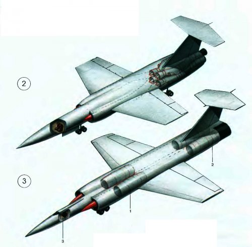
Hi! M-60 nuclear bomber two types.
http://tehno-science.ru/voennaya-texnika-710.html

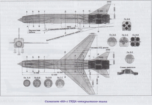
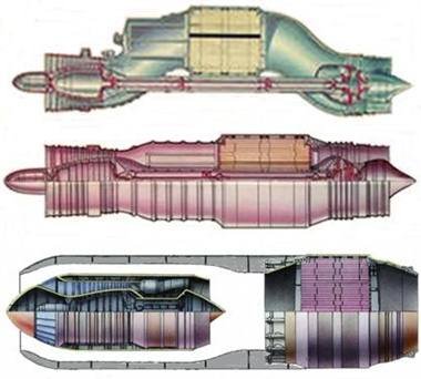
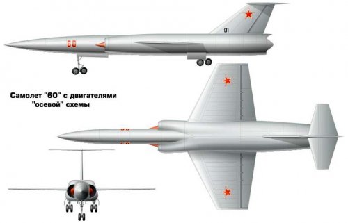
②. M-60 with engines rocker "schema:
takeoff weight is 225 tons, payload-25 t, altitude is 13-25 km, length — 58.8 m, wingspan — 30.6 m.

③. M-60 with a combined engine, flight characteristics are the same length: 51.6 m, wingspan is 26.5 m; are marked by numerals:
1—turbojet engine; 2-Atomic Reactor; 3 — the cockpit. (Nuclear reactor was used as afterburner.)

④. combined turboreaktivno-Atomic engine:
1-electric starter; 2-flap; 3-air duct straight through circuit; 4-compressor;
5— the combustion chamber; 6-nuclear reactor; 7 — fuel Assembly.

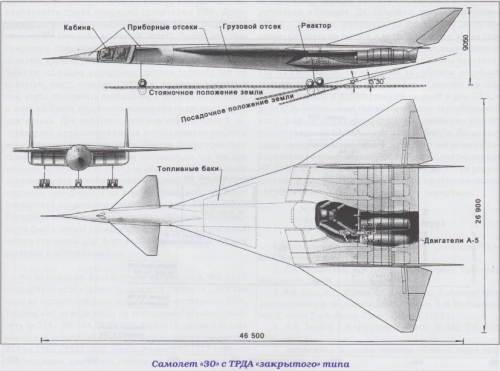
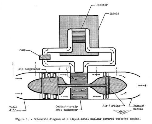
Bottom picture shows M-30 nuclear bomber project with closed system nuclear jet engine. Red color part shows nuclear reactor. Primary heat transfer system(coolant :for example liquid Na, boiling temperature 882.8°C) is closed to confine radioactive substance. Engine intake air was heated by heat exchanger.

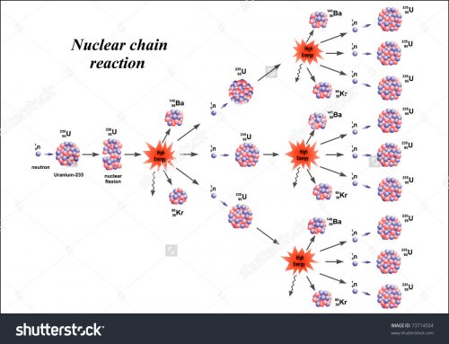
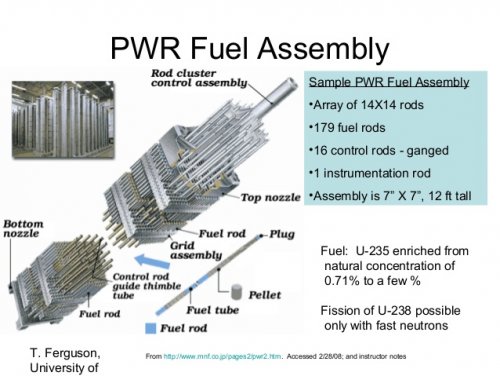
PWR : Pressurized Water Reactor. Reactor power control is conducted by control rod which insert to the fuel assembly to absorb nutron generated by chain reaction.
 

Attachments

  • chain reaction.jpg
    chain reaction.jpg
    125.2 KB · Views: 105
  • anp-ic-2.jpg
    anp-ic-2.jpg
    108.1 KB · Views: 107
  • session-10-nuclear-power-17-638.jpg
    session-10-nuclear-power-17-638.jpg
    88.3 KB · Views: 141
  • m30.jpg
    m30.jpg
    15.1 KB · Views: 152
  • M-60M CUTAWAY.jpg
    M-60M CUTAWAY.jpg
    79 KB · Views: 139
  • Atomolety-5.jpg
    Atomolety-5.jpg
    139 KB · Views: 119
  • Atomolety-4.jpg
    Atomolety-4.jpg
    75 KB · Views: 122
  • Atomolety-2-3.jpg
    Atomolety-2-3.jpg
    141.4 KB · Views: 129
Oh you did it!! ;)


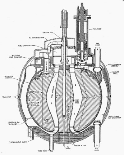
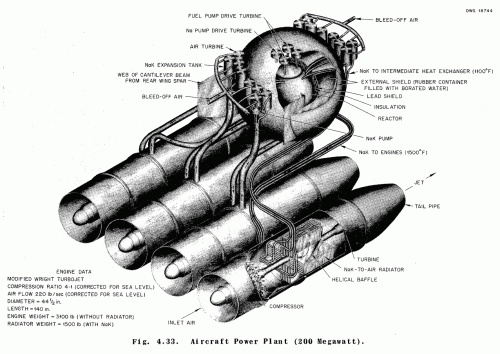
Surprisingly this design has intermediate heat transfer loop. Coolant of primary heat transfer loop is fluoride salt with liquid fuel which generate fission heat at reactor moderated flow pass(center of the reactor which surrounded by beryllium metal refrection moderator that moderate nutron to increase chain reaction). Coolant of secondary heat transfer loop is Nak. Heat transfer between primary heat trasnfer loop and secondary heat transfer loop is conducterd by intermediate heat exchanger(IHX).
Engine intake air is heated by Nak to air radiator. Perhaps fatally heavy system for the aircraft.
Engine inlet Nak temperature is 1500°F(815.6°C).

"Heat generated in the fluoride salt was removed by a liquid sodium coolant loop and then dumped in an air-cooled heat exchanger. The ARE(Aircraft Reactor Experiment) showed that not only was the UF4 chemically stable in the solvent, but also that the fission products generated by fission formed stable fluorides in the salt mixture and did not plate out on surfaces. Another surprise was that gaseous fission products were removed essentially automatically by the pumping action of the reactor, accumulating in the pump bowl above the reactor. The fluid fuel had a very strong negative temperature coefficient, and the reactor could easily be started and stopped by changing the power demand on the reactor, without control rods. Despite its success, the engineers were not anxious to run the reactor for an extended period, since the “in-and-out” tubular configuration could not drain the salt from the core in the event of an accident. After 8 days the reactor was shut down.

Flushed with success from the ARE, ORNL engineers proposed the liquid-fluoride reactor as the baseline for the Aircraft Reactor Program and it was selected. Plans were made to build a “real” liquid-fluoride reactor that would operate at 60 MWt and would be of a flight-like configuration. This reactor was to be called the Aircraft Reactor Test, but the engineers referred to it as the “Fireball”
. The Fireball was a reflector-moderated design that used the NaF-ZrF4-UF4 fuel of the ARE, but was moderated by beryllium metal and cooled by liquid sodium-potassium eutectic (NaK). The NaK was planned to carry the fission heat to the turbojet engines that would provide thrust to the aircraft in flight."
 

Attachments

  • nuclear reactor.jpg
    nuclear reactor.jpg
    227 KB · Views: 682
  • a0e98eefbb27209fc6b48de96d581fa2.gif
    a0e98eefbb27209fc6b48de96d581fa2.gif
    131.6 KB · Views: 698
Hi!


Attachments

  • M-60 VARIANT 1 (2).jpg
    M-60 VARIANT 1 (2).jpg
    53.4 KB · Views: 633
  • M-60 VARIANT 1 (1).jpg
    M-60 VARIANT 1 (1).jpg
    26.6 KB · Views: 612
  • M-60 VARIANT 2 MODEL.jpg
    M-60 VARIANT 2 MODEL.jpg
    38 KB · Views: 603
  • M-60 VARIANT 2.jpg
    M-60 VARIANT 2.jpg
    53.1 KB · Views: 107
  • M-60 SEAPLANE.jpg
    M-60 SEAPLANE.jpg
    72.8 KB · Views: 121
Hi! Chinese site.
"This is the nuclear-turbojet engine СКБ-500 designed for the Milacherx. Soviet engineers tested several types of nuclear-powered engines, including ramjet engines, turboprops, and turbojet engines. Engineers have repeatedly tested the different transmission mechanisms of the engines, with a focus on verifying the heat transfer of the nuclear reactors. After extensive trials and repeated scenarios between the engine and the transmission system, the Soviet engineers concluded that the direct cycle of the turbojet is the best option. Designers decided to use a direct cycle of energy transmission mode. This method will use the reactor as the energy source of the power plant to replace the combustion used by the jet engine.
In the direct recycle energy transfer device, the incoming air is first fed into the compressor of the turbojet engine and then passed through a duct that directs air to the reactor core. This time into the air as a reactor coolant at the same time is heating up. The air behind the core reactor reactor is returned to another air duct and is ejected from there through the turbine of the engine. "

Perhaps this engine also act as pure nuclear ramjet engine to shut control valve located front of the turbojet engine.

Engine structure: 1-electric start, 2-control valve, 3-ramjet housing , 4-compressor, 5-combustor, 6-flight control system, 7-fuel assembly
 

Attachments

  • m50_engine.jpg
    m50_engine.jpg
    35.3 KB · Views: 111
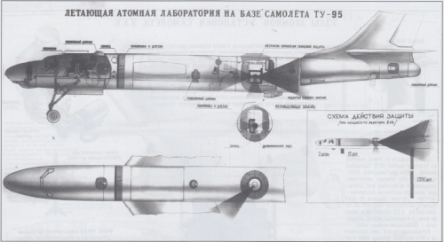
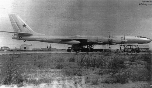
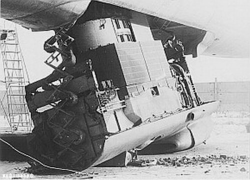
"Tupolev is well aware of the complexity of the task, the Bureau of the Group estimated that the manufacture of a prototype to up to 20 years time! Because a lot of technology is still immature or there are research and development problems, so the aircraft really shape to be time. They considered the first experimental nature of the nuclear power as a supporting power of the aircraft until the late 1970s or early 80s to launch. The purpose of the current program is to explore the feasibility of the technology. At the end of 1955, the designers began the first phase of the design and testing of a small nuclear reactor. In March 1956, the Soviet ministerial meeting designated Tupolev as soon as possible to produce flight test platform. Tupolev engineers decided to convert the existing chart-95M bomber into a "flying nuclear laboratory". The final figure -95LAL turned out.

By 1958, after the nuclear reactor was installed, the aircraft was ready for ground phase testing. During the summer of 1958, the nuclear power plant began testing. Shortly after the test, the designer was surprised to find that the reactor power reached the previously set requirements. The expert group immediately decided to begin preparations for the flight pilot phase. Between May and August 1961, Figure -95LAL completed 34 flight test missions. "

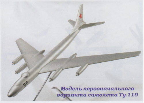
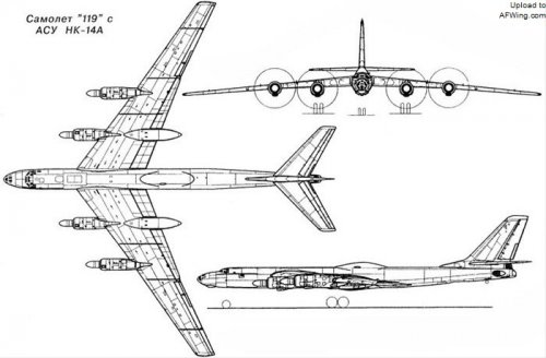
"All of the test flight, Figure -95LAL nuclear power plant are in a closed state. The main purpose of the flight is to obtain the flight parameters of the modified aircraft to verify that the machine is suitable as the ultimate nuclear power plant equipped with aircraft. A large amount of liquid sodium, beryllium oxide, cadmium, paraffin and fine steel are used to make the radiant cockpit - the core part that protects the pilots from lethal radiation. The result is so exciting Tupolev Design Bureau. It is estimated by the instrument that the radiation level in the cockpit is low, which paves the way for the design of a new body that can meet the actual requirements. The next stage of the program is to produce a new verification machine. This design from the outset will be nuclear energy as its main driving force. This new verification machine number 119 is designed on the basis of Figure -95.

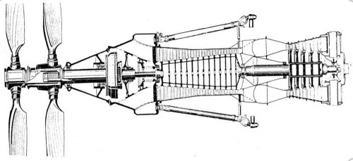
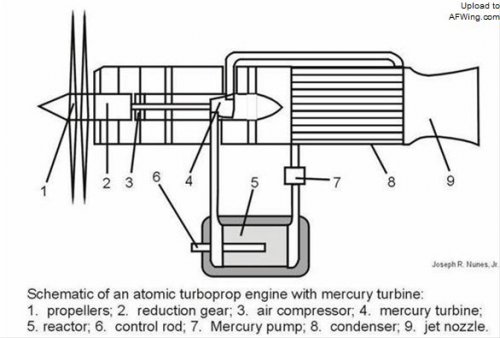
The main difference with the general figure -95 is that there are two of its four engines for the NK-14A turboprop engine with new heat exchangers installed. NK-14A is a very similar direct-loop engine. The main difference is that the air through the compressor, and did not lead to the reactor, but directly to the heat exchange system. At the same time, the heat generated by the nuclear reactor passes through the fluid to the heat exchange system. The combination of these two forces will allow the engine to produce the thrust required. The other two outboard engines are NK-12M. "

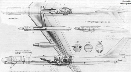
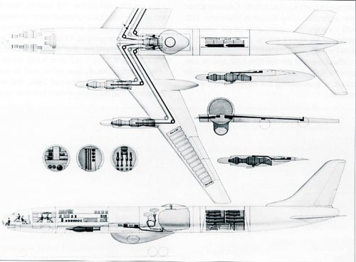
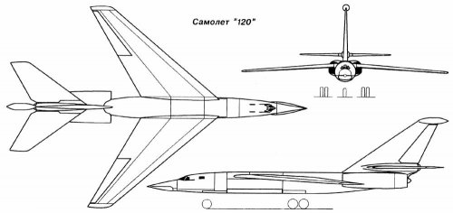
"At the same time when the Kuznetsov Design Bureau developed the engine, the schematic of the 119 aircraft was completed. The inside of the drawing shows that the internal magazine will place the reactor. From the reactor to the engine connecting pipe through the main body, and then forked up to the two wings, and ultimately directly connected to the two NK-14A engine heat exchanger. Tupolev estimated that by the end of 1965, 119 would take the airport takeoff and landing tests. After the test, the mixed engine group of No. 119 was replaced by four all-in-one NK-14A engines. The replacement of the NK-14A is different from the earlier test flight used. New engine changed from Figure -114 Business flight using NK-14A. However, the original drawings did not make any changes to the 119 facelift engine. Perhaps this episode seems to imply that the whole plan is stalled. In August 1966, due to budget constraints and major design bureaus took over the design task of developing new conventional aircraft, time-consuming, and not very safe figure-95LAL project came to an end. The cancellation of the plan did not mean that the Soviet Union had terminated its nuclear-powered aircraft research project. Because the same period, the other nuclear-powered aircraft project did not dismount. For example, later on the implementation of No. 117 in the 120 project. 120 is different from 119, it is nuclear power supersonic bomber project verification machine."
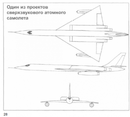
Around this project, the Soviet Union made a lot of research. The Soviet Union will focus on the new turbojet engine research and development and re-layout of the nuclear reactor system research. The newly designed system is required to provide more protection to crew and airborne avionics systems. 120 is expected to install the two new turbojet engines designed by the Kuznetsov Design Board. This time the installation of the reactor is different from the 119 practice, but installed in the tail. The reason is simple, the reactor from the cockpit farther the better, is to reduce the radiation on the crew of the most vulnerable to the law. The crew consisted of pilots, co-pilot and navigator, and their seats were placed in a heavy, confined, radiation shielded cockpit. 120 with 45 degrees swept wing, rear swept wing and front triangular landing gear design. From the appearance point of view, compared with the previous use of the traditional power of the Tupolev series bombers compared to 120 does not seem bloated. The goal of the Tupolev Design Bureau was to complete all R & D and testing work in the late 1970s and then put it into use. Unfortunately, 120 did not wait until that day. And 119 the same reason, 120 project in 119 after dismount was canceled. This plane did not even made the prototype of the 120 long-range fighting dream can only dusty in the yellowing of the design drawings.

Tupolev design bureau has made the next attempt. It is 132. But 132 is generally considered to be an attacker, not a bomber required by the plan. The installation of the power plant is similar to that of 120, and the reactor is mounted at the tail, before the two turbojet engines. And the entire power system all on the tail, unlike 119 and 120 there are still many auxiliary parts installed in the machine throughout. This engine can be operated either by conventional kerosene and by nuclear power. However, the Soviet designers only intend to use kerosene for aircraft takeoff and landing. All kerosene is poured into a special cabinet type container in front of the reactor. The other parts of the aircraft are almost the same as 120, but the right inside made some changes.

(Engine is like this?)
http://www.secretprojects.co.uk/forum/index.php?action=dlattach;topic=855.0;attach=575109;image
(Or like this? In this case air route to conbustion chamber or to mercury to air heat exchanger is selected by control valve?)
http://www.secretprojects.co.uk/forum/index.php?action=dlattach;topic=855.0;attach=575139;image

132 is expected to use delta wing, which is likely to be considered an important reason for attack aircraft. The tail is also used in the back sweep design, the level of stability in the wing roof. Technical problems quickly let 132 into a dead end. 132 was canceled in the mid-1960s. The last effort of the Tupolev Design Bureau was a plane that had not yet been completed. The aircraft is designed to be a supersonic bomber designed to compete with the US-based B-58 medium bomber.
However, by the funding, technology, security and other factors under the influence of the Soviet Union in the late 60's nuclear power aircraft enthusiasm finally exhausted. The Soviet Union decided to end all the projects launched, while giving up the results of the feasibility study. In general, the reason for the end of the plan is that the nuclear strike capability of the intercontinental ballistic missiles on the Soviet nuclear submarines is more accurate and cheaper (relative to the development of nuclear power aircraft). For the implementation of the planned economy of the Soviet Union, to strengthen the already underwater nuclear strike capability than to continue in the nuclear-powered aircraft this project burn more cost-effective. "

Of course No.3 drawing is little strange. Condenser(heat exchanger) should be located at front of the turbine.
I imagine that NK-14A engine shape is almost same as NK-12 turboprop engine. Nk-14A had condenser(mercury to air heat exchanger) instead of NK-12 conbustion chamber. Mercury to air heat exchanger must be very large compared with conbustion chamber.
 

Attachments

  • The first frame - 95LAL, code 119.jpg
    The first frame - 95LAL, code 119.jpg
    77.5 KB · Views: 122
  • NK-12.jpg
    NK-12.jpg
    65.7 KB · Views: 127
  • NK-14A.jpg
    NK-14A.jpg
    26 KB · Views: 114
  • Figure -95 Several designs of nuclear bombers.jpg
    Figure -95 Several designs of nuclear bombers.jpg
    53.1 KB · Views: 130
  • tu114.jpg
    tu114.jpg
    80.7 KB · Views: 135
  • tu95-119-2.jpg
    tu95-119-2.jpg
    60.9 KB · Views: 124
  • nk14.jpg
    nk14.jpg
    38.7 KB · Views: 119
  • tu-95_119.jpg
    tu-95_119.jpg
    52.5 KB · Views: 137
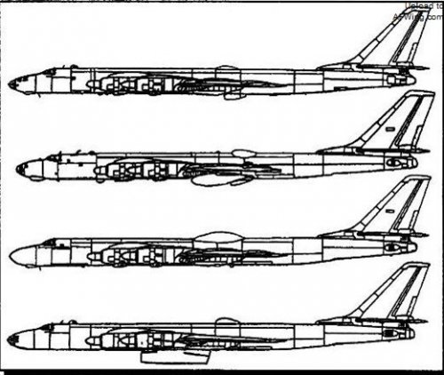
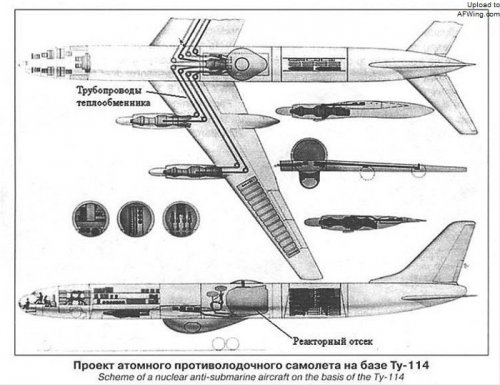
Tu-114 nuclear engine ASW larger image, 120 three side view and Tu-95LAL mercury cooling nuclear reactor.
 

Attachments

  • Project Atomic ASW aircraft TU-114.jpg
    Project Atomic ASW aircraft TU-114.jpg
    113.1 KB · Views: 177
  • 120.jpg
    120.jpg
    59.8 KB · Views: 189
  • Tu-95LAL. Dismantling the reactor.jpg
    Tu-95LAL. Dismantling the reactor.jpg
    72.6 KB · Views: 190

Similar threads

Please donate to support the forum.

Back
Top Bottom