You are using an out of date browser. It may not display this or other websites correctly.
You should upgrade or use an alternative browser.
You should upgrade or use an alternative browser.
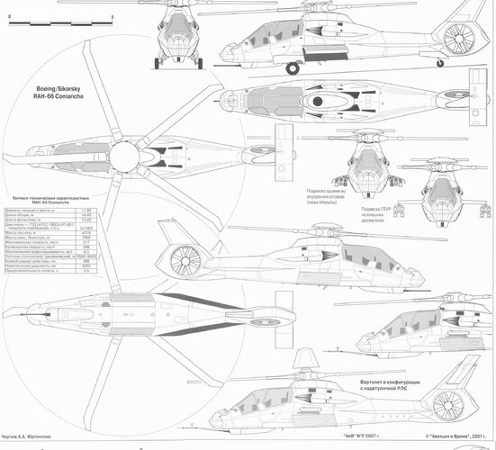
Boeing/Sikorsky RAH-66 Comanche
- Thread starter Stuka
- Start date
Scott Kenny
ACCESS: USAP
- Joined
- 15 May 2023
- Messages
- 11,553
- Reaction score
- 14,169
I hope to add a few pictures of a 1/144 scale model, as soon as I can figure out how to get the rotor to look as if it's in flight.@hesham - my friend you will be able to make a career out of RAH-66 Comanche pictures!
- Joined
- 29 July 2009
- Messages
- 1,768
- Reaction score
- 2,467
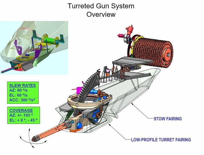
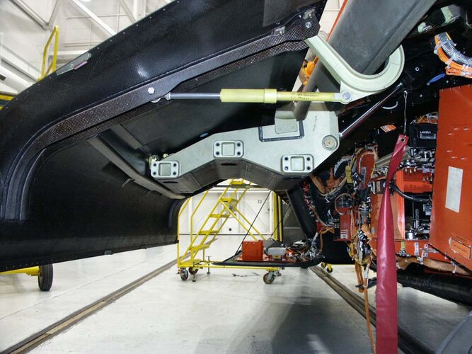
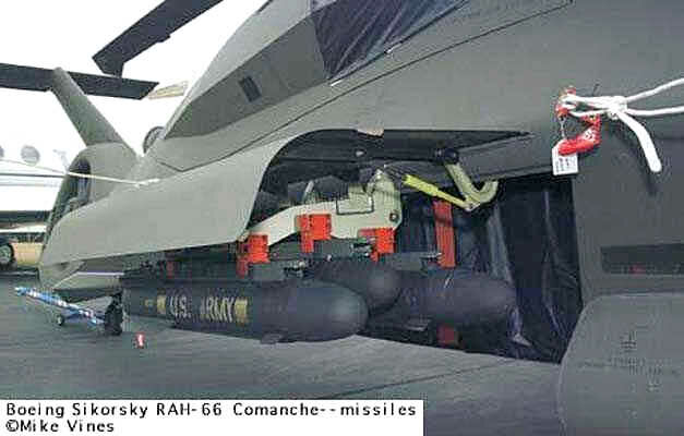
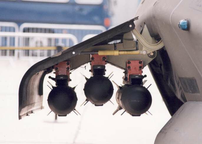
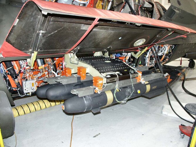
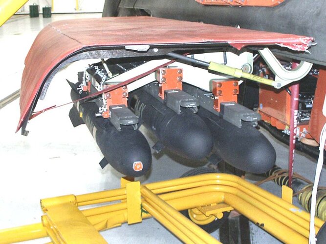
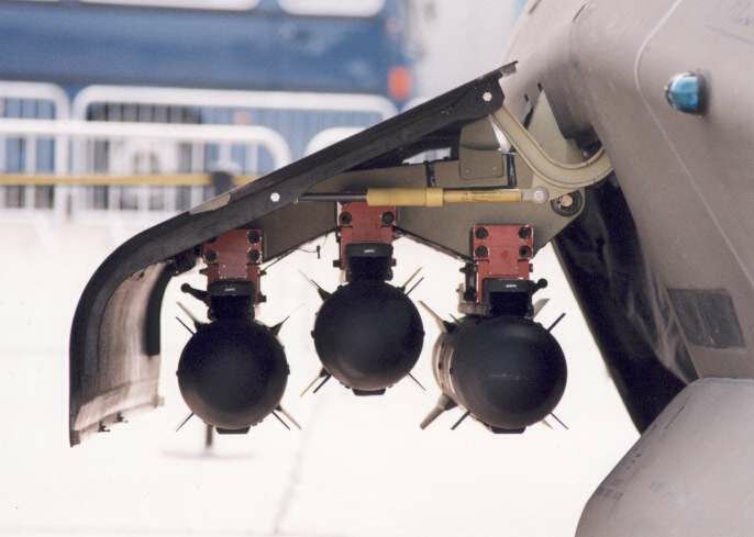
I have seen pictures with Comanche carrying the AIM-92 Stinger missiles on the ground, deployed on its weapons pallet from its weapons bay, however were there ever live fire tests conducted with the Stinger or the Hydra rockets? I'm not sure the Comanche even fired its 20 mm cannon from the helicopter. Below is a static test of the Comanche's 20 mm cannon at the end of the video.
View: https://www.youtube.com/watch?v=RlsaGV7ULAs
- Joined
- 26 May 2006
- Messages
- 34,873
- Reaction score
- 15,734
@hesham - my friend you will be able to make a career out of RAH-66 Comanche pictures!
Ok my dear Yasotay.
- Joined
- 18 October 2006
- Messages
- 4,208
- Reaction score
- 4,901
The Comanche program never fired any weapons from the aircraft. The cannon was ground tested.I have seen pictures with Comanche carrying the AIM-92 Stinger missiles on the ground, deployed on its weapons pallet from its weapons bay, however were there ever live fire tests conducted with the Stinger or the Hydra rockets? I'm not sure the Comanche even fired its 20 mm cannon from the helicopter. Below is a static test of the Comanche's 20 mm cannon at the end of the video.
@Dynoman - great video! Thanks for finding it.
Last edited:
Scott Kenny
ACCESS: USAP
- Joined
- 15 May 2023
- Messages
- 11,553
- Reaction score
- 14,169
I haven't found any good photos that show how much the rotor blades flexed up relative to the bottom of the radar housing.I hope to add a few pictures of a 1/144 scale model, as soon as I can figure out how to get the rotor to look as if it's in flight.
Did the blade tips roughly get to the bottom of the antenna, or were they higher than that?
Scott Kenny
ACCESS: USAP
- Joined
- 15 May 2023
- Messages
- 11,553
- Reaction score
- 14,169
That's kinda what I figured, but wanted to confirm.Going on memory, the rotor system was not designed to flex to a point where part of the rotor disk was above the bottom of the radar. At least not intensionally .
Scott Kenny
ACCESS: USAP
- Joined
- 15 May 2023
- Messages
- 11,553
- Reaction score
- 14,169
Pardon me, re-reading this thread.
So a modern equivalent would send the exhaust up through the rotor? How does that improve the IR signature, given the complaints about the H1 "toilet bowl"?Indeed stealth was one of the considerations, but also with the flight regime expected having a protected tail rotor in an NOE environment is a good thing. Statistically many of the (US) Army's aircraft losses are to pilot error do to rotor strikes.
The rotor systems was put through a huge effort to make it less detectable, although the results might be debatable. Acoustically, the shrouded TR made the aircraft much more quite. Having been ~600 meters upwind from the aircraft in a stable hover, it was virtually silent. As it got closer the first noise detected was the transmission. Of course for acoustic sensors, all this is irrelevant. Ironically with todays flight profiles (higher) RAH-66 would have been at a terrible disadvantage with its downward facing exhaust.
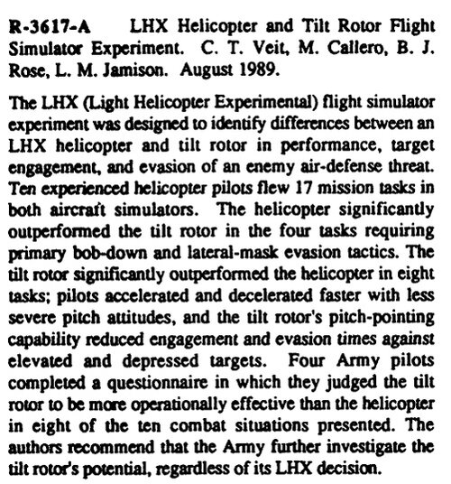
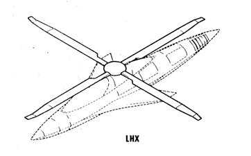
Does anyone have a copy of that RAND report? I'm interested in the 10 attributes and what missions they were "flying".The decision to go with a conventional helicopter was dictated by the Secretary of the Army. Fearing a long process to bring new technology to fruition, it was directed. RAND Corp. did a study on ten attributes for the aircraft and used senior Army aviation (warrant) officers to do the simulation runs to compare a conventional rotorcraft and a tilt rotor LHX. At the end of the study these officer had assessed that six of ten were performed better by the tilt rotor, two were tied and two were better executed by the conventional rotorcraft. Ironically the two done better by standard rotorcraft were reconnaissance and security missions. The SecArmy's position was validated. RAND recommended a conventional helicopter for the mission be built but that the Army continue to look seriously at tilt rotor technology for other missions. A recommendation promptly ignored, other than a conventional rotorcraft.
- Joined
- 29 July 2009
- Messages
- 1,768
- Reaction score
- 2,467
This is a synopsis of the report, R-3617-A LHX Helicopter and Tilt Rotor Flight Simulator Experiment, 1989.Does anyone have a copy of that RAND report?
Attachments
- Joined
- 29 July 2009
- Messages
- 1,768
- Reaction score
- 2,467
- Joined
- 29 July 2009
- Messages
- 1,768
- Reaction score
- 2,467
BLACK_MAMBA
ACCESS: Secret
- Joined
- 17 July 2019
- Messages
- 382
- Reaction score
- 877
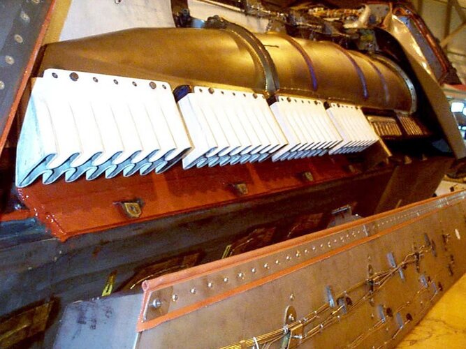
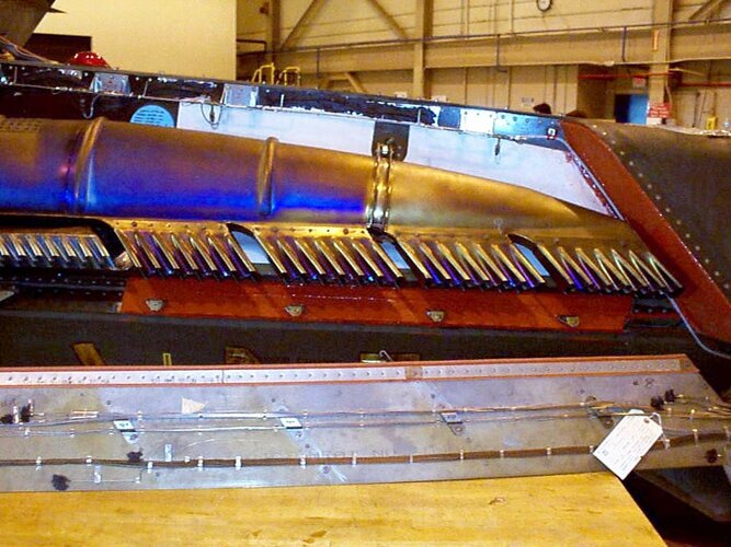
It seems Westland and their LO helicopter studies had the best overall approach from a signature viewpoint which is a side facing exhaust exiting into the direction the main rotor is turning. As per usual ambient air is mixed with the hot exhaust air and is then vented into the swirling air caused by the rotor as it moves over the fuselage. This swirl and the direction of the exhaust rapidly mixes the exhaust air with ambient where it dissaptes. The added benefit is the hot air is taken away from the fuselage preventing heat build-up on the fudelage which would cause an increased IR signature. Upward facing exhausts heat the main rotor blades and thus create an increased IR signature there. The downside of this system would be the increased complexity and physical space required I guess.So a modern equivalent would send the exhaust up through the rotor? How does that improve the IR signature, given the complaints about the H1 "toilet bowl"?
Scott Kenny
ACCESS: USAP
- Joined
- 15 May 2023
- Messages
- 11,553
- Reaction score
- 14,169
Thank you!This is a synopsis of the report, R-3617-A LHX Helicopter and Tilt Rotor Flight Simulator Experiment, 1989.
Scott Kenny
ACCESS: USAP
- Joined
- 15 May 2023
- Messages
- 11,553
- Reaction score
- 14,169
Interesting. That must be quite a pain to work with widely-spaced twin engines, like most US helos...It seems Westland and their LO helicopter studies had the best overall approach from a signature viewpoint which is a side facing exhaust exiting into the direction the main rotor is turning. As per usual ambient air is mixed with the hot exhaust air and is then vented into the swirling air caused by the rotor as it moves over the fuselage. This swirl and the direction of the exhaust rapidly mixes the exhaust air with ambient where it dissaptes. The added benefit is the hot air is taken away from the fuselage preventing heat build-up on the fudelage which would cause an increased IR signature. Upward facing exhausts heat the main rotor blades and thus create an increased IR signature there. The downside of this system would be the increased complexity and physical space required I guess.
- Joined
- 26 May 2006
- Messages
- 34,873
- Reaction score
- 15,734
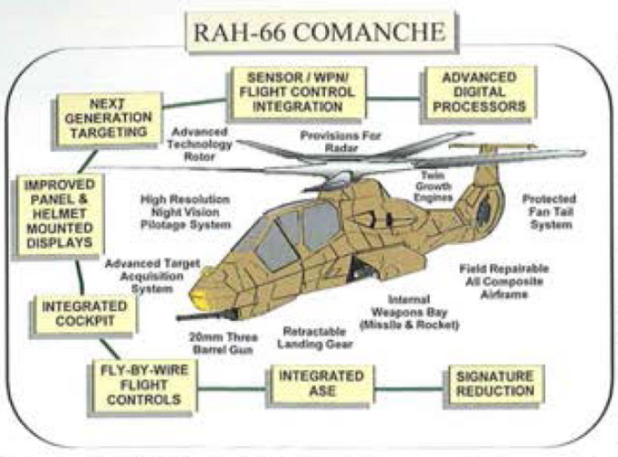
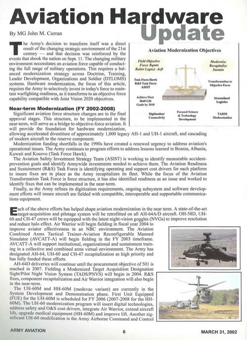
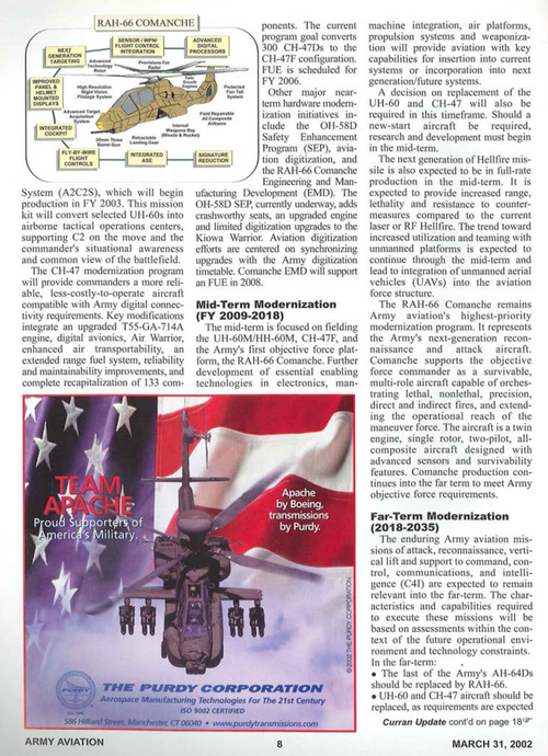
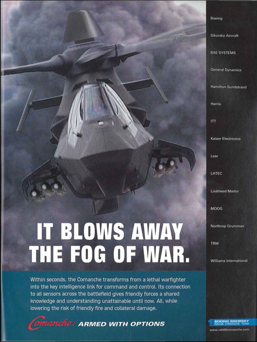
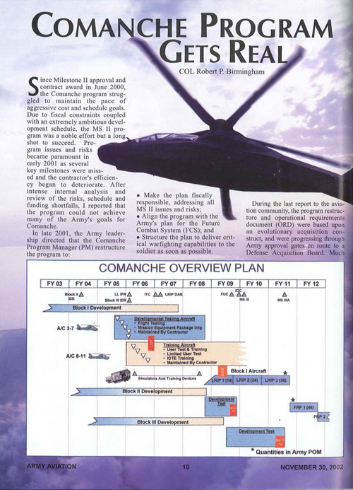
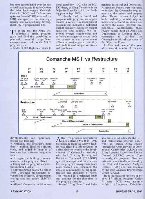
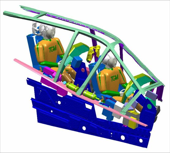
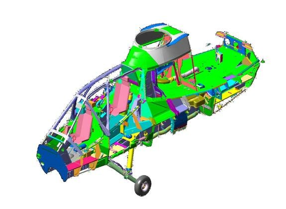
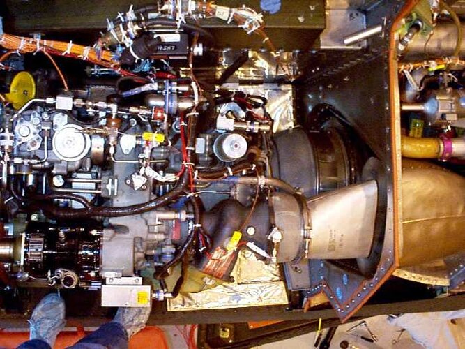
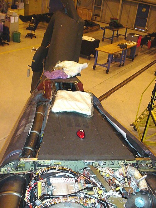
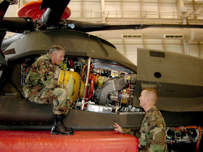
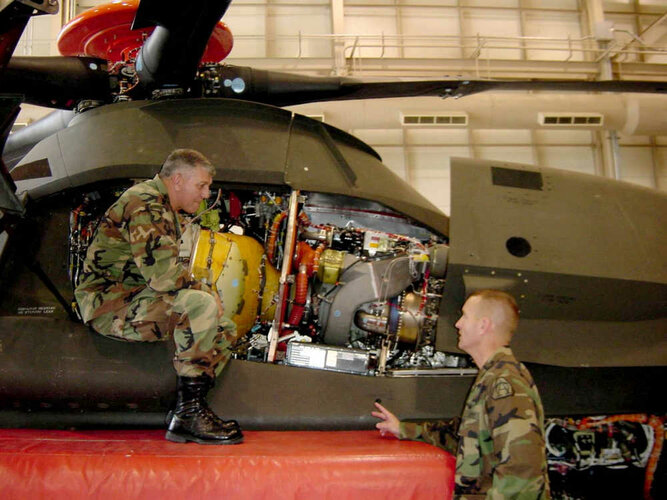
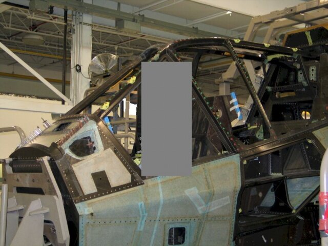
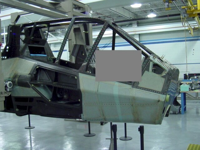
From Army Aviation 2002/10.
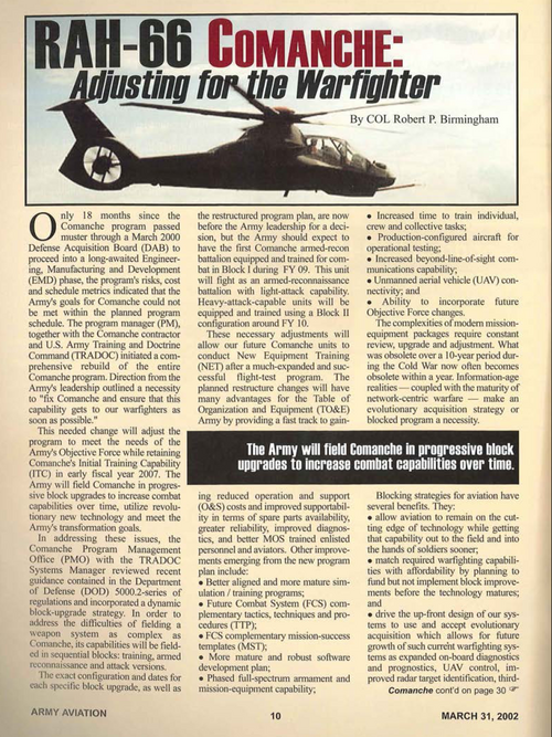
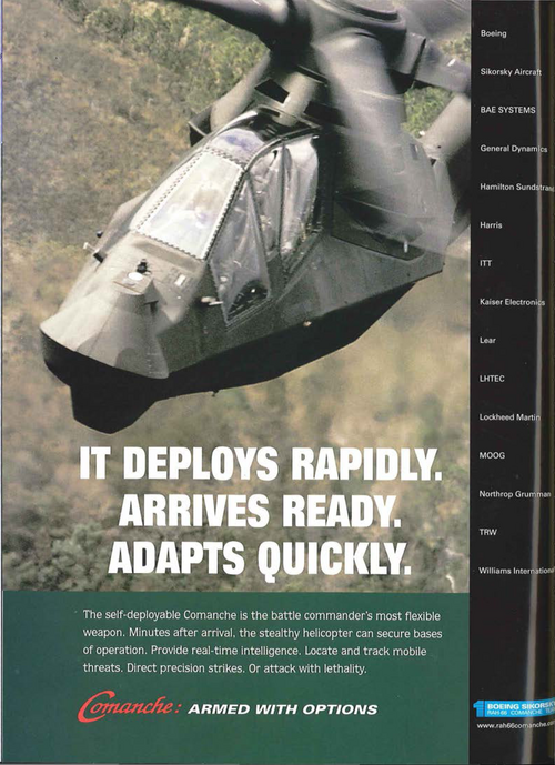
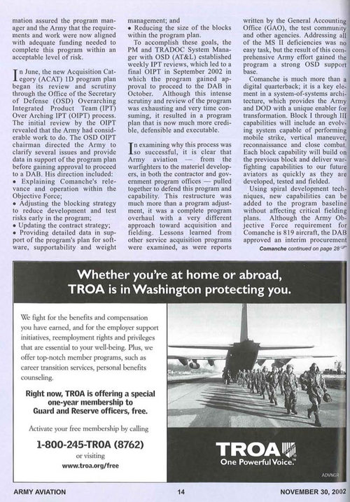
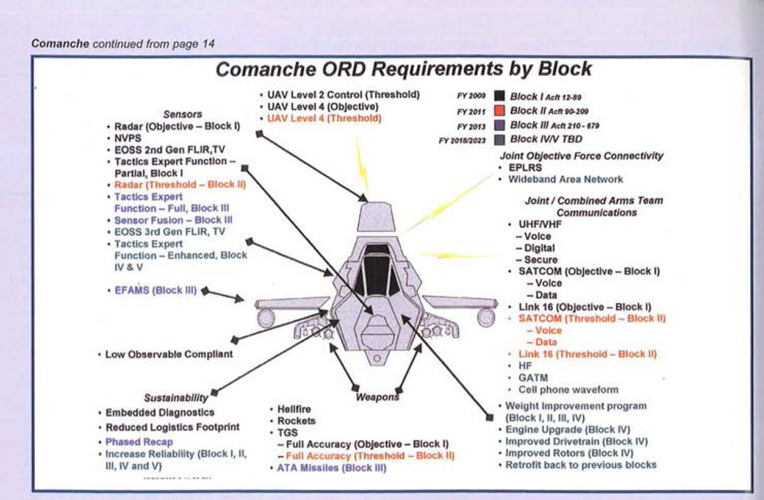
Also from Army Aviation 2002/11.
Attachments
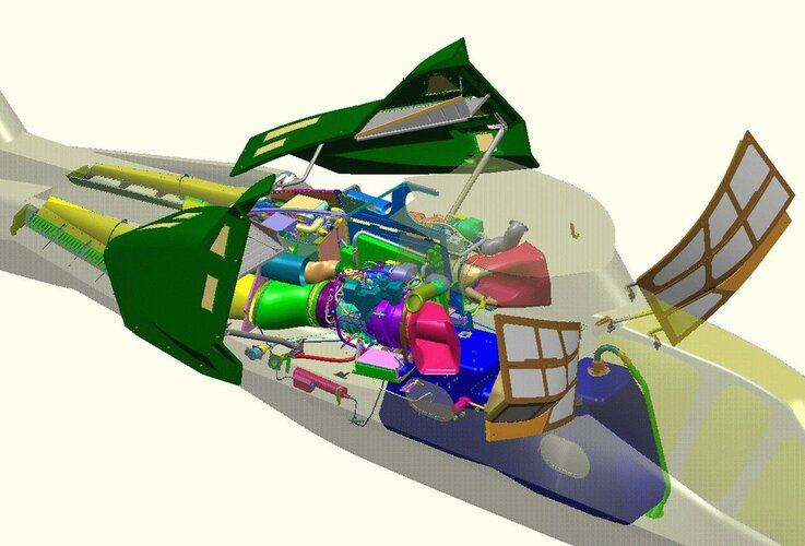
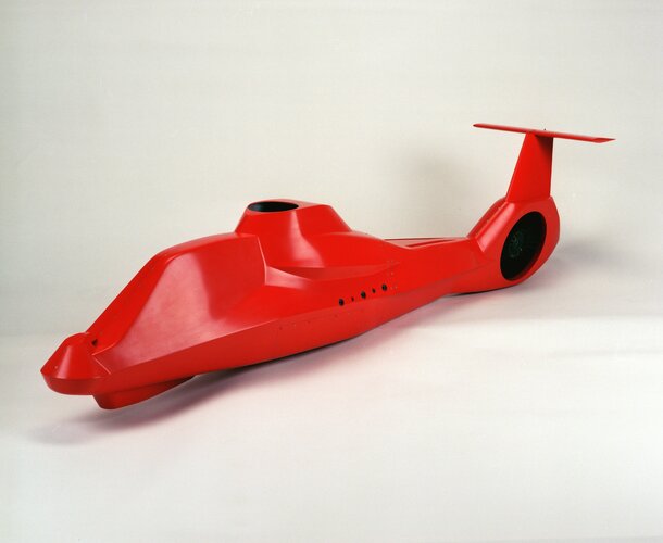
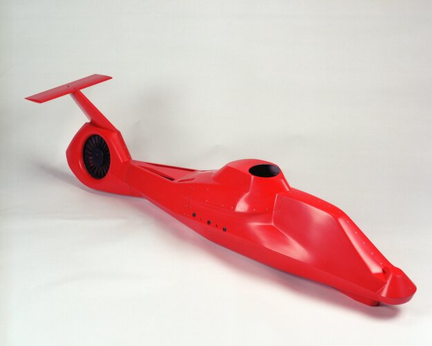
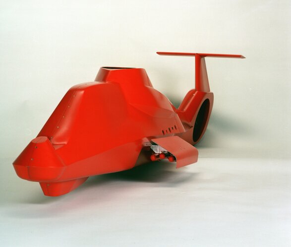
Aft Fuse.
Regards,
Regards,
Attachments
-
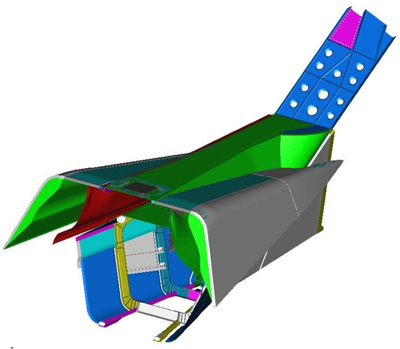 AftFuseLageTailconeStructure.jpg42.6 KB · Views: 43
 -
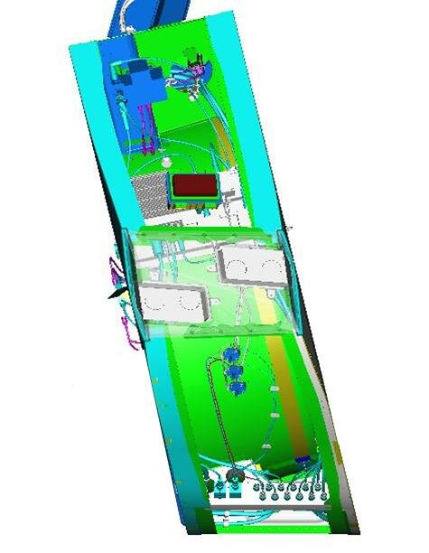 AftFuselageSystemIntergrationShrouda.jpg34.4 KB · Views: 38
 -
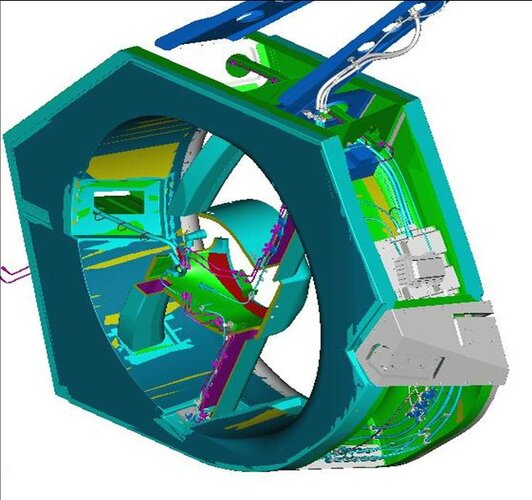 AftFuselageSystemIntergrationShroud.jpg59.3 KB · Views: 36
 -
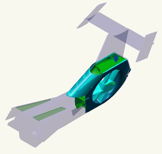 AftFuselageShroud.jpg32.2 KB · Views: 32
 -
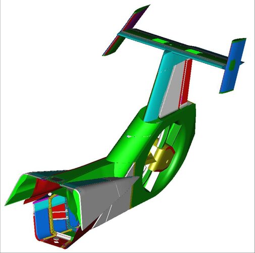 AftFuselagea.jpg49.1 KB · Views: 32
 -
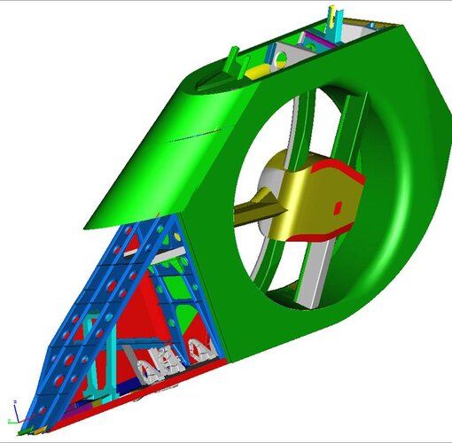 Aftfuselage.jpg66.3 KB · Views: 34
 -
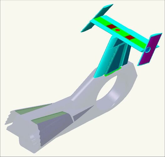 AftFuseEMP.jpg31.7 KB · Views: 36
 -
 AftFuse.jpg10.7 KB · Views: 34
Similar threads
-
-
-
-
-
Bell Boeing V-22 Osprey - Development and Proposed Variants
- Started by JC Carbonel
- Replies: 308

