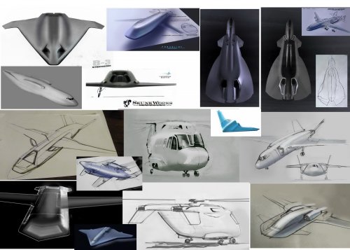
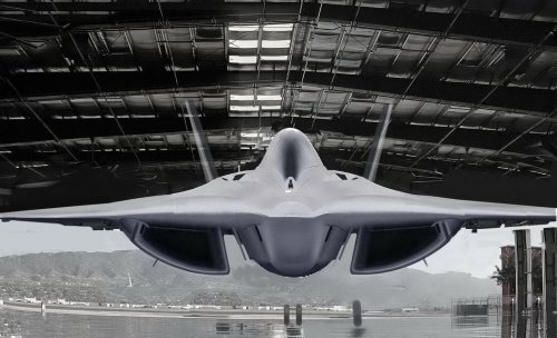
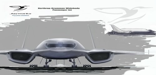
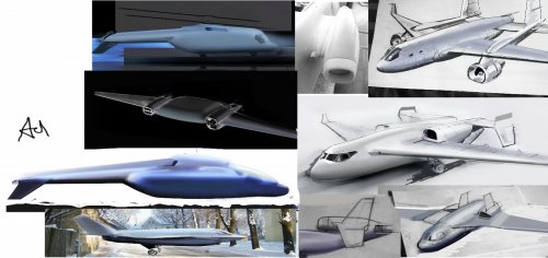
Fascinating way you integrated wing leading edge and engine nacelle on the NGW airliner!
Existing prodded engine nacelles are easy to maintain and solve several structural functions, but interference drag can be a b@&$!
Example: the hassle Boeing goes through every time they up-engine their 727.
By "easy to maintain" I mean quick access via large, hinged panels/hatches. Separate nacelles also facilitate quick engine changes by allowing access from most angles. At minimum you want to retain easy access to half or 3/4 the circumference of the engine. Think about easily approaching it with a replacement engine on a fork-lift.
Structurally, nacelles hang the weight/mass forward of the wing spar/structure reducing flutter tendencies.
Aerodynamically, it is simpler to keep the engine inlet even with or ahead of the wing leading edge, to keep smooth airflow into the engine.
I have often wondered if the World War 2-vintage B-24 bomber would have been more efficient if they had squared the engine surpercharger intakes, flattened them and blended them into the wing's leading edge and top skin???????
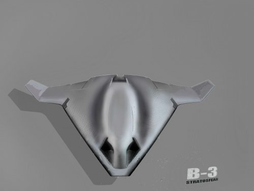
Your sketches are amazing in that you seem to intuitively understand most of balance and aerodynamic concepts while still sketching more graceful, flowing lines than anyone else.
Could we please see more of your sketches of engine nacelles blended into wing leading edges or tail leading edges?
Maybe a spiral leading edge extending from the wing center-section blended into the leading edge of the engine nacelle on your BOREAL?


