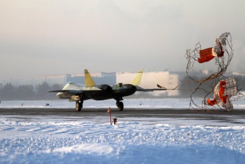
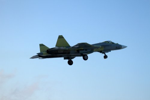
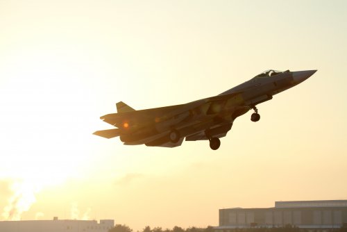
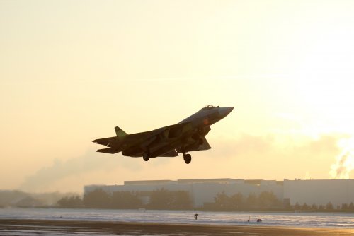
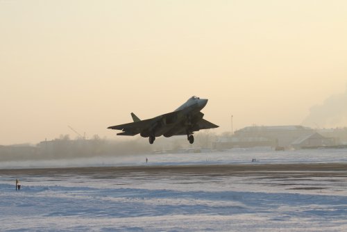
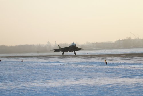
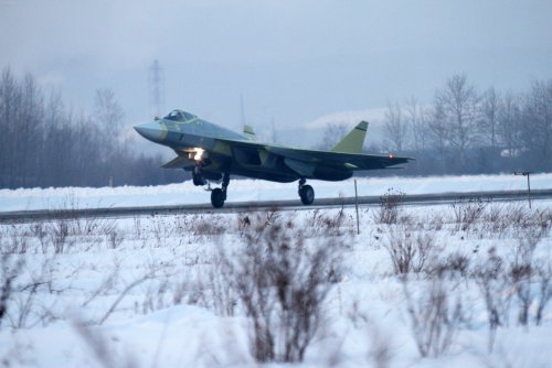
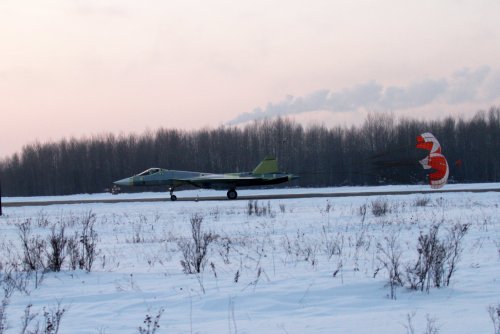
Sukhoi Su-57 / T-50 / PAK FA - flight testing and development Part II [2012-current]

Sundog said:
In the YF-23 vs T-50 debate, you have to consider frontal area and surface area are more of a concern for subsonic performance, not supersonic. For supersonic performance, you're better off looking at the wave drag (Area distribution) and the fineness ratio. Just saying...

Do we have any cross sectional references on the T-50? From a quick glance, the T-50's similar configuration to the YF-23 seems to indicate that it's better area-ruled than the F-22.
 
Hello!

Some info and images of PAK FA Aesa radar here:

http://espacial-org.blogspot.com.ar/2012/08/caracteristicas-generales-del-radar-del.html

and:

http://espacial-org.blogspot.com.ar/2012/08/el-radar-del-pak-fa-inicia-sus-pruebas.html

Best wishes!

B)
 
In my opinion, the Pakfa looks like a much more inherently stable airplane than the f-35 or f-22. It looks as though the Russians wanted to save money and cut design risk by using/relying on the Levcons to pitch the nose upward to get tail lift, much like the f-22/35 use their unstable designs to pitch the nose up, which allows the tail to lift together with the wing.


Were those overworked Levcons to malfunction, the pilot is stuck with a stable and less maneuverable aircraft.


On the f-22/35 the wings and horizontal tail are way back behind the back of the aircraft, and the tail is always providing lift with the main wing. on the Pakfa, the tail is much farther forward on the fuselage, more stable, more conventional.


The Pakfa needs to bump its Levcons for trim to keep that nose pitched up and get tail lift. its much more stable for supercruise, but not as inherently unstable as the f-35/22.


My point is that the Pakfa looks more conventional and stable in its design for the reasons I mention above.
 
I don't think we've ever seen the LEVCONs deflect upwards before, which would be required for them to generate a nose-up moment for trim. Doing so would probably not be good for aerodynamics either, since it would result in a good deal of drag due to the separation of the boundary layer just behind the LEVCON. As far as I can tell, their main function is to deflect downwards at high alpha to reduce drag and therefore energy loss in turns.

I think I may do a comparison (based on schematics) to see how the tail volume of the T-50 compares with the F-22. Let's also not forget that an aircraft can be unstable even if the tail volume is small; having the center of gravity behind the center of lift is sufficient (although the center of lift moves back to around 40-45% of the Mean Aerodynamic Chord at supersonic speeds versus 25% at subsonic speeds. Not that it would necessarily have to be unstable at supersonic speeds; I believe the Typhoon is unstable subsonic and stable supersonic).
 
Kryptid, I have seen a few pictures of the T-50 taking off where the levcons appear to be deflected upwards slightly <5 degrees, check a few of the previously posted pictures out. Again, I'm not sure, was just offering an opinion. I would imagine it could trim either way to prevent excessive nose pitch and controllability at high AoA.


What are you're (and others') thoughts on the fact that Sukhoi (possibly) used this as a lower risk approach rather than making the aircraft much more unstable like the f-22/35? After all, the Russians have used operational canard (Levcon related) aircraft, whereas the USA has never used the canard approach, instead preferring a highly unstable/tail lift design.
 
The Levcons deflect upwards during take-off. If you've seen the schematics, you might want to rethink about being "less risky" structure wise.
 
Really? Huh. That's quite interesting. I guess the separation drag at the low speeds during take-off must not be too bad. Then again, a mere 5 degrees probably wouldn't cause much such drag anyway.
 
kcran567 said:
What are you're (and others') thoughts on the fact that Sukhoi (possibly) used this as a lower risk approach rather than making the aircraft much more unstable like the f-22/35? After all, the Russians have used operational canard (Levcon related) aircraft, whereas the USA has never used the canard approach, instead preferring a highly unstable/tail lift design.
Canard aircraft can be highly unstable as well - this is not a matter of canard or tailed configuration. Also, it seems counter-intuitive that Sukhoi would ditch what is in effect an established approach by now - a direction no less that they helped pioneer back in the 1970s - for an untried solution (LEVCONs). And if risk reduction was the aim, why then build what is probably the world's first aircraft that is significantly unstable in yaw?
It doesn't compute - there isn't much about the T-50 configuration that could be called conservative, it's right up there with the YF-23 in this regard.
 
I guess I wanted to know why the main wing and tails aren't farther back on the T-50 like the f-35 and f-22, and we know those two rely on unstable design and tail lift for subsonic/supersonic agility. It looks as if the center of lift and gravity on the t-50 is further forward than on the f-35 for example. The Levcons are a way that Sukhoi avoided making the t-50 design as longitudinally unstable as the f-35 for example. But in YAW, the all-moving and small verticals make Sukhoi appear to be much more unstable than the f-35 or the f-22. I'm puzzled.


My opinion that I offered was that the T-50 is more longitudinally stable, but the Levcons can be used to trim the nose up, ultimately achieving tail lift like the more unstable f-35/22.
 
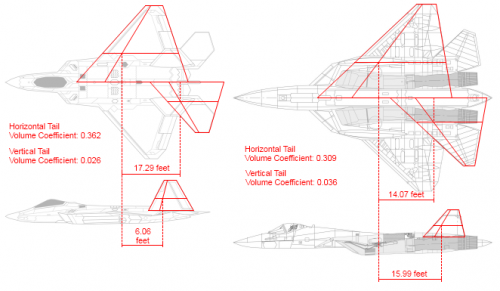
Here are my estimations of the tail volume coefficients for the F-22 and the T-50.

For further comparison, the production F-23A schematic posted elsewhere on this site mentions its horizontal tail volume coefficient as 0.169 and its vertical tail volume coefficient as 0.087. I also have the horizontal tail volume coefficients for several other aircraft: F-15 (0.5382), F-16 (0.4726), F/A-18 (0.594), F-5 (0.528), F-4 (0.2584), F-104 (0.495), MiG-21 (0.4185), Jaguar (0.5544), MiG-25 (0.4386). It's interesting to note how the F-23A, F-22A and the T-50 have fairly small horizontal tail volume coefficients when compared to other aircraft. Perhaps that's a result of improved computer flight control systems or more advanced airfoils? With the F-22 and T-50, at least the TVC nozzles can add to the pitching authority.

Note: the aircraft are not to scale in the following image.
 

Attachments

  • RaptorComparison.png
    RaptorComparison.png
    73.7 KB · Views: 422
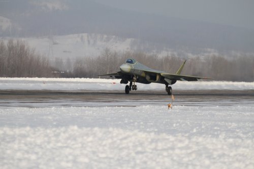
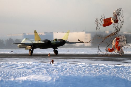
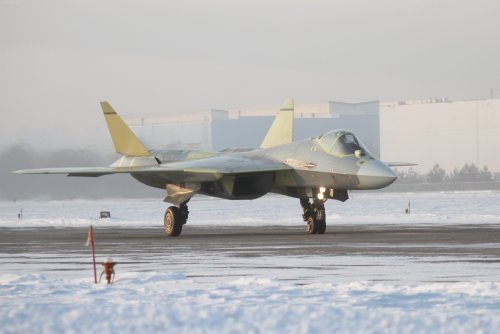
thanks to grOOmi, we know that T50-4 is in the air
 
Any news or even images !!!??? Anyway congrats .... ;)

Deino
 
photos as usual should proceed security screening...KnAAPO and Sukhoi media staff working better and better, so should expect soon
so far even UAC media service doesn't have 'em
 
Was this the one that was supposed to have 2-dimensional nozzles, or will we have to wait until the service-ready version is complete?
 
kcran567 said:
I guess I wanted to know why the main wing and tails aren't farther back on the T-50 like the f-35 and f-22, and we know those two rely on unstable design and tail lift for subsonic/supersonic agility. It looks as if the center of lift and gravity on the t-50 is further forward than on the f-35 for example. The Levcons are a way that Sukhoi avoided making the t-50 design as longitudinally unstable as the f-35 for example. But in YAW, the all-moving and small verticals make Sukhoi appear to be much more unstable than the f-35 or the f-22. I'm puzzled.


My opinion that I offered was that the T-50 is more longitudinally stable, but the Levcons can be used to trim the nose up, ultimately achieving tail lift like the more unstable f-35/22.

I don't know about how unstable the T-50 design is, but judging from the huge control surfaces and wide lifting body, I don't see this plane turning any worse than the F-22. Coupled with its better area ruling (based on its similar configuration to the YF-23), I can see the F-22 struggling if it enters the merge with the T-50
 
Kryptid said:
Was this the one that was supposed to have 2-dimensional nozzles, or will we have to wait until the service-ready version is complete?
no/most likeley there will be no 2D at all
 
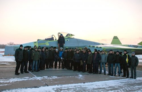
according to grOOmi, 2nd flight was performed today
 
flateric said:
Kryptid said:
Was this the one that was supposed to have 2-dimensional nozzles, or will we have to wait until the service-ready version is complete?
no/most likeley there will be no 2D at all

So, no up-engined aircraft with IR shrouded nozzles and rear-facetting planned as a follow-on in the 2030s-2040s?
 
Avimimus said:
flateric said:
Kryptid said:
Was this the one that was supposed to have 2-dimensional nozzles, or will we have to wait until the service-ready version is complete?
no/most likeley there will be no 2D at all

So, no up-engined aircraft with IR shrouded nozzles and rear-facetting planned as a follow-on in the 2030s-2040s?

I recall Flateric was mentioning about some patent filed (not public as yet) by Pogosyan/Davidenko to do with 'swiveling nozzles'. See his posting no 306 on keypubs-> http://forum.keypublishing.com/showthread.php?p=1803234
Swiveling nozzles will apparently do away with the need for flat nozzles.
Its not clear if the said swiveling nozzles will appear on that so-called 'Type-30' variant of the engine which is slated to be fitted on PAK-FA in 2015 timeframe.
I also find it a bit odd that patents for engine nozzles are being filed by Pogosyan and Davidenko. Shouldnt those be filed by Eugene Marchukov/NPO Saturn?
 
...
 

Attachments

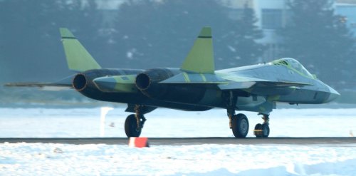
  • t50-4-13.jpg
    t50-4-13.jpg
    189.5 KB · Views: 621
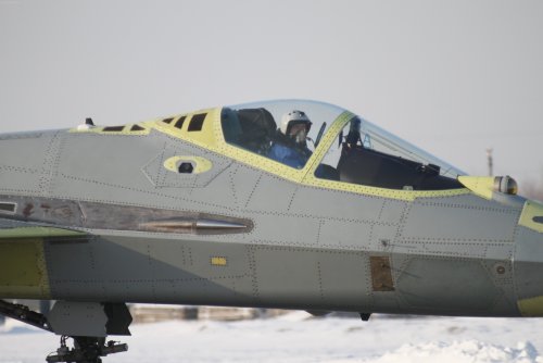
new additions:

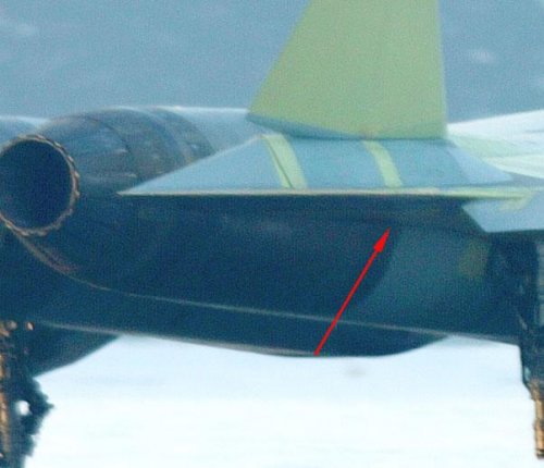
  • 2 side facing cameras behind the cockpit
  • yellow panels on the upper fuselage in front of the engines (?)
 
hello!

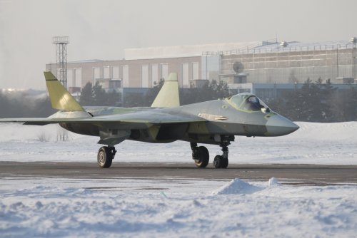
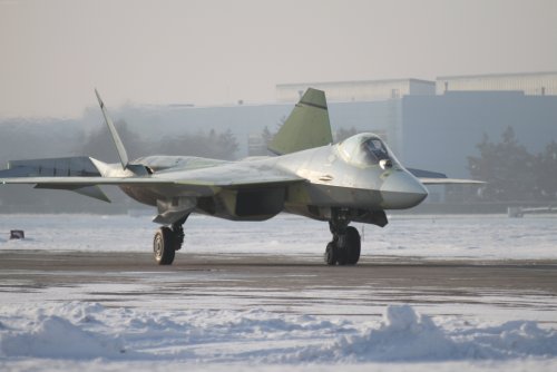
images of four prototype of PAK FA...

Best wishes....
 

Attachments

  • 2.jpg
    2.jpg
    217.6 KB · Views: 355
  • 3.jpg
    3.jpg
    38.3 KB · Views: 335
Patent:

GLIDER MULTIMODE highly maneuverable aircraft

http://www.findpatent.ru/patent/246/2462395.html

The invention relates to an aircraft heavier than air. Constructive power circuits fuselage includes transverse and longitudinal strength members presented respectively fuselage frames (17-25) and the longitudinal walls (26-29). A set of longitudinal walls (26-29) through the entire medium (3) and tail (5) of the fuselage. Center section (12) arranged in the plane of maximum building heights of the wing and formed frames (17-25). At the bottom of the fuselage made large longitudinal cuts for cargo compartments (10) and (14). Constructive power circuits cutouts includes longitudinal walls 26 are connected with the center-frames (12). The invention is directed to redistribute power components arising from the stress of external loads due to the rational arrangement of the power components of the frame glider. 3 Description: f-ly, 6 ill.
The invention relates to an aircraft heavier than air. Preferred area of ​​application of the invention are multi-mode highly maneuverable aircraft operated both in the pre-and supersonic speeds.
State of the art multi-mode known glider plane, which contains the wing and center section with consoles, combined with middle part of the fuselage, empennage. The fuselage includes the cabin crew compartments to accommodate fuel, equipment, and landing gear. The glider has at least one turbofan engine mounted in nacelles, located in the rear fuselage, with attached to it with an air supply inlet channel him. Frame airframe with longitudinal and transverse members that are bound together with the relevant panels. The wings and the center section made caisson and aft fuselage and the part between the cabin crew and the center section made of semi-monocoque. Said glider disclosed in the utility model RU, 4109, U1, 1997
As disadvantages of the prior art can be specified as follows. In organizing the cutouts in the lower part of the fuselage under the cargo space in the known structure is necessary to strengthen the power cut additional elements, such as beams, which inevitably leads to a significant increase in the weight of the airframe and the deterioration of the performance of the aircraft as a whole.
The problem to be solved by the invention is to provide the necessary strength and rigidity of the frame glider with a small increase in the presence of its mass in the lower part of the fuselage of large cutouts cargo compartments. This delivers technical result consists in the redistribution of power components arising in airframe stress from external loads due to the rational arrangement of the power components of the frame glider.
The inventive in that glider multimode highly maneuverable aircraft comprising a fuselage and wing design and power circuits are formed by longitudinal and transverse load-bearing elements, to which the lining that forms the outer contour of the airplane, with fuselage compartment includes cabin crew compartments placement of fuel, equipment and landing gear, tail, two located in the rear fuselage nacelle for a turbojet engine and docked them air intakes with an air supply channels and wing includes consoles connected with the center, combined with middle part of the fuselage, structural power circuits fuselage is in the longitudinal direction of multi-structure, which is connected with the center, formed by bulkheads and connected by torque and pivot nodes wing panels, structural power circuits wing panels in the longitudinal direction is mnogolonzheronnuyu design in combination with the walls, the outer surface of the airframe formed a power strip , at the bottom of the fuselage made large longitudinal cuts for cargo compartments, structural power circuits which includes longitudinal walls, connected with the frames of center, center is located in the zone of maximum building heights of the wing, and the lower power panel intakes and nacelles are located further away from the neutral line section fuselage, and large longitudinal cuts close to the neutral line of the fuselage.
Power panels can be made, for example, in the form of multi-layer, three-layer in particular, panels made of polymer composite materials.
Power panels can be made of aluminum alloy Wholly.
Power panels can be made of welded titanium alloy.
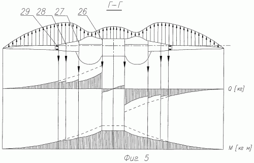
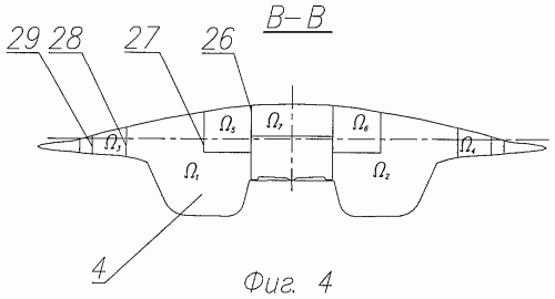
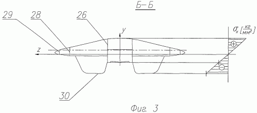
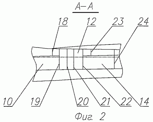
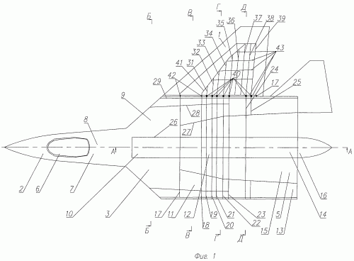
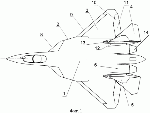
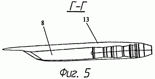
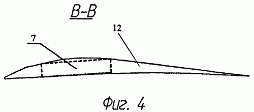
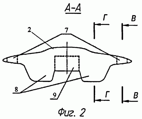
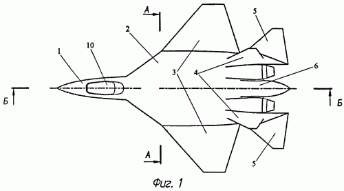
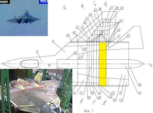
The invention is illustrated by drawings in which Figure 1 shows a glider aircraft with a multi-mode in the plan in Figure 2 - cross section AA of Figure 1, Figure 3 - section B-B Figure 1, Figure 4 - section BB in Figure 1, Figure 5 - section YY Figure 1, Figure 6 - section D-D Figure 1.
Glider multimode highly maneuverable aircraft (hereinafter - the glider) has a wing consisting of two consoles 1, head of the fuselage 2, the middle part of the fuselage 3, 4 intakes, rear fuselage 5. The head part of the fuselage 2 includes cabin 6, equipment bays 7 and 8 niche nose landing gear. In the middle of the fuselage has three fuel bays 9, cargo compartment 10, cut 11 main landing gear and the center section 12. The aft fuselage fuel bays 5 are 13, the cargo compartment 14, the nacelle 15, tail section 16 equipment.
Constructive power circuits fuselage includes transverse and longitudinal strength members presented respectively fuselage frames 17-25 and 26-29 longitudinal walls. A set of longitudinal walls 26-29 through the entire secondary 3 and 5 tail of the fuselage. Center section 12 arranged in the plane of maximum building heights of the wing (sech. YY) and the resulting frames 17-25. At the bottom of the fuselage made large longitudinal cuts for cargo compartments 10 and 14. Constructive power circuits cutouts includes longitudinal walls 26 are connected with the center-frames 12.
4 intakes and nacelle 15, in terms of design and power circuits formed frames 17-25 and lower power panel 30.
Constructive power circuits consoles one wing includes longitudinal and transverse load-bearing elements. Longitudinal strength members consoles 1 shows spars 31, 32, 34, 35, 38 and 39 with torque units 40 one console connection with the center 12 and the walls 36, 37, 41 with hinge 42 nodes connect with the center console 1 12. Center-frames 12, which means the torque units 40 are connected consoles spars 1, made by force. Transverse force set console 1 is a set of ribs 43.
The main force factors, based on which, the necessary strength and rigidity to the fuselage, it is bending in the longitudinal plane of the airplane (relative to the axis Z) from inertial and air forces and pressures that come with the horizontal tail, the transverse bending of the load coming from the console one wing and torsion.
1 shows a projection of scheduled airframe multimode highly maneuverable aircraft. The lift wing panels 1 is transmitted through hinge assemblies 42 and 40 on the torque units fuselage frames 17-25. This group frames lift passes from the wing to the fuselage longitudinal walls 26-29. A set of longitudinal walls 26-29, passing through the entire secondary 3 and 5 tail of the fuselage to reduce the gradient of increase of the bending moment (Figure 5) in cross-section fuselage and provide a lower level of normal stresses in the zones close to the plane of symmetry frames aircraft that in turn, reduces the weight of the fuselage frames and deformation in the transverse direction.
In addition, to increase the stiffness of the airframe of the transverse bending cargo compartments 10, 14 are separated by the center section 12 (see Figure 2). Power center-frames 12, organized in a plane of maximum building heights of the wing (sech. YY), perceive the bending moment on the wing by the torque units 40. Thereby reducing the amount of strain in the transverse direction - in - in the sections on the cargo bay (sech. B-B, B-B, D-E).
The outer surface of the airframe formed a power strip to perceive all kinds of stress - normal and tangential. Power panels can be made, for example, in the form of multi-layer, three-layer in particular, panels made of polymer composites or metal: Wholly of aluminum alloy welding of titanium alloy. Power panels are connected with longitudinal walls 26-29 and 17-25 fuselage frames and frame rails 31, 32, 34, 35, 38, 39 and the walls 36, 37, 41 consoles one wing.
The normal stresses of lateral bending in the longitudinal plane fuselage aircraft perceived upper and lower power panel fuselage, with a cut-out cargo bay doors located near the neutral axis (Z)-sectional plane than the lower power panel 30 pods 15 and air intake 4 (Fig. 3). In accordance with (1) - definition of normal stresses in the section in bending - the value of the normal stress in the lower power panel inlets 4 and nacelle 15 is higher than in the area of ​​cut-out cargo bay doors.

where
M z - bending moment in the section of the fuselage;
J z - moment of inertia of the fuselage axis Z (neutral line);
y - distance from the neutral section line to the point of the cross section, which defines the voltage.
Thus, the main part of the fuselage bending loads from the bottom of the perceived lower power panel 30 inlets 4 and nacelle 15.
Of multi-fuselage provides the perception of torque on the fuselage. Torque coming from the rear fuselage (differential deflection GO, variations in, etc.), is perceived by closed loops 1 , 2 , , n (see Figure 6) and is transmitted to the rear of center rib 23. Said frame 23 transfers torque to the group of closed loops 1 , 2 , , m (see Figure 5). The large number of closed loops in the fuselage section of the fuselage provides high torsional rigidity and does not require major cuts in the cargo compartment under the organization of special force elements - beams. In addition, significantly increases the combat survivability of the aircraft, as the case of damage of any closed circuit in accordance with (2) the flow of tangential force is redistributed to other circuits.

where
M cr - torque at the section of fuselage;
M kpi - torque of the i-th section of the fuselage.
The normal stresses of bending moment arising consoles 1, seen in the main belt spars 31, 32, 34, 35, 38, 39 and partially power panels. Voltage from one wing torsion consoles perceived power panels and rib belts 43.

Claim
1. Glider multimode highly maneuverable aircraft comprising a fuselage and wing design and power circuits are formed by longitudinal and transverse load-bearing elements, to which the lining that forms the outer contour of the airplane, with fuselage compartment includes the cockpit, cut to accommodate the fuel, equipment and landing gear, tail, two located in the rear fuselage nacelle for a turbojet engine with attached thereto air intakes with an air supply channels and wing includes consoles connected with the center, combined with middle part of the fuselage, wherein the power circuit design and fuselage is longitudinally towards the construction of multi-connected to the center-formed frames and connected through a hinge moment and nodes with wing panels, structural power circuits wing panels in the longitudinal direction is mnogolonzheronnuyu design in combination with the walls, the outer surface of the airframe formed a power strip at the bottom of fuselage made large longitudinal cuts for cargo doors, design and power circuits which includes longitudinal walls, connected with the frames of center, center is located in the zone of maximum building heights of the wing, and the lower power panel intakes and nacelles are located further away from the neutral line of the fuselage cross-section, and large longitudinal cuts close to the neutral line of the fuselage.
2. Glider according to claim 1, characterized in that the power panel in the form of multi-layer, three-layer in particular, panels made of polymer composite materials.
3. Glider according to claim 1, characterized in that the power panel Wholly made of aluminum alloy.
4. Glider according to claim 1, characterized in that the power panels are welded titanium alloy.


[Added pics & translation to original post - Admin]
 

Attachments

  • 2747161.gif
    2747161.gif
    9.2 KB · Views: 57
  • 2747160.gif
    2747160.gif
    46.1 KB · Views: 52
  • 2747159.gif
    2747159.gif
    9.6 KB · Views: 48
  • 2747158.gif
    2747158.gif
    13 KB · Views: 44
  • 2747157.gif
    2747157.gif
    7.6 KB · Views: 244
  • 2747153.gif
    2747153.gif
    53.7 KB · Views: 256
Details of the T-50 intake design (link posted earlier by SaintKatanaLegacy)


http://www.findpatent.ru/patent/246/2460892.html


(54) METHOD FOR CONTROLLING hypersonic inlet

(57) Abstract:
The invention relates to aviation technology, namely the air intakes of power plants supersonic aircraft. In the management of a supersonic inlet throat area and change the position of shock waves through the simultaneous rotation of the front panel and adjustable rear adjustable panel. Pivot adjustable front panel coincides with the line of intersection of the first and second stages of a swept wedges, not perpendicular to the incoming stream. The axis of rotation of the rear panel is adjustable in the back area of ​​the trailing edge of the panel and adjustable focus conditions for the existence of the point of intersection with the axis of rotation of the front panel adjustable. When you rotate the front and rear panels of the controlled side edges move relative profiled flanks channel without forming gaps between them. The invention improves the gas-dynamic characteristics of the air intake, as well as to reduce its radar signature. 3 Description: f-ly, 8 ill.
The invention relates to aviation technology, namely the air intakes of power plants supersonic aircraft. Preferred area of ​​application of the invention are turbojet aircraft with a maximum of up to Mach 3.
Creating a low-profile in the LC-range aircraft (LA) means that the shape of all the elements help to reduce the effective area of ​​cross section (RCS) of aircraft. This applies to the login form, engine air intake. In order to achieve the desired result all edges intake should be swept and parallel to some elements of aircraft (the edges of the wing, tail, etc.). The implementation of such intake has high intrinsic characteristics in all operating range, is impossible without regulation.
Adjustable, typically performed by braking surface air intake (for example, a wedge or cone). At supersonic speeds, changing angle of the surface of the brake leads to change of stagnation in the inlet, and the change in the area of ​​his throat. Together, the effect of this regulation provides a high performance air intake in the entire range of the aircraft on which it is installed.
There is a method of regulation of the supersonic plane (two-dimensional) air inlet, the surface of which is represented by a multi-stage braking nestrelovidnym wedge (Reme NH "Aerodynamics intakes of supersonic aircraft." Ed. TsAGI, Zhukovsky, 2002, 178 p.). In a decision intake control is carried out with respect to the rotary axes of the respective panels. The panels are located in the channel one by one. The front panel contains a step wedge brake, except the first. Its axis coincides with the line of intersection of the first and second stage of the wedge. The rear panel is part of the channel and has a complex shape. Rear axle passes over its rear edge. Lack of edge and sweep step wedge brake allows parallel to the axis of rotation of panels perpendicular to the incoming stream. Disadvantage of control plane intake in relation to the air intake with swept edges is not feasible to control the axes perpendicular to the direction of flow, as all elements are swept inlet mouth.
As a prototype of the invention, a method of regulation adopted supersonic air intake, which is carried out change in the area and the position of the throat shocks (RU 2343297 C1). In a decision is implemented spatial deceleration of the flow by using a V-shaped wedge (ie two adjacent swept wedges oriented to each other from the front at an obtuse angle). The air intake is made with giving sweep all edges entrance. Intake control is performed by two pairs of rotating relative to the corresponding axes of panels. The front panel of each of the pairs are part of the braking surfaces. The rear panels are part of the channel. In the management of each pair of panels between their adjacent end faces of a transverse crack, and between them the sides of a longitudinal slit along the seams as the side walls and along the seams together. This solution has the following disadvantages:
- A way to control the air intake does not provide the necessary throat area at subsonic and low supersonic flight speeds, as amplitude of moving panels is low. Otherwise, there is said longitudinal slit unacceptable proportions. This means that the air intake does not provide the job in all turbojet operational speed range and is not a multi-mode;
- Technically complex implementation method for controlling air intake.
The technical result for aim of the invention is to provide a possibility of changing the angle of the steps of one of the arrow-shaped wedges braking and minimal air intake passage area (throat) with no education in its channel unwanted longitudinal slots and seizure of mobile elements. Such a regulation would, in turn, ensure stable operation of the engine in all modes of the aircraft up to Mach number of M = 3.0 with full pressure recovery coefficient at the inlet to the engine, with at least a model for regulated plane intake and total non-uniform flow below the maximum permissible value ("Aerodynamics, stability and control of supersonic aircraft", ed. G.S.Byushgensa. - Moscow: Nauka. Francis, London, 1998). Thus due to the parallelogram shaped inlet to the front view and giving all its edges is achieved by reducing the sweep of radar visibility of the object on which it is installed. The greatest effect of reducing the radar signature will be achieved when the edge of the air intake in some parts of the object parallel to the (front or rear edge of the wings, tail, etc.).
This technical result is achieved by a method for control of a supersonic air intake, which is carried out change in the area and the position of the throat shocks, changes in the area of ​​the throat and the position of shocks by simultaneously turning adjustable front panel, the rotation axis coincides with the line of intersection of the first and second stage one of the arrow-shaped wedges that is not perpendicular to the oncoming flow, and an adjustable rear panel, the axis of rotation of which is located in the area of ​​the rear edge of the rear panel, controlled and directed from the condition of having a point of intersection with the axis of rotation of the front panel, adjustable, thus when you turn the front and rear panels of the controlled lateral edges are moved relative profiled flanks channel without forming gaps between them.
Also, when you turn the front and rear panels of controlled orientation transverse slit between the top view does not change, and its position coincides with the line passing through the point of intersection of the axes of the front and rear adjustable panels, while the gap is close to rectangular shape with any possible position adjustable panels.
Also, when you turn the front and rear panels of controlled panel shutters rotate relative to the axis of its rotation and oriented in such a way that a common point of intersection between the axis of rotation and an adjustable rear panel.
Also, when you turn the front and rear panels of regulated changes position kinematically related rotary wing covering the transverse slot on the unregulated airbrake in the throat.
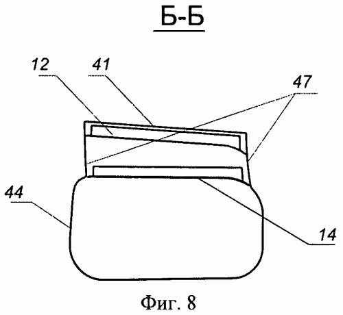
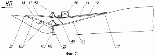
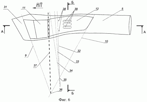
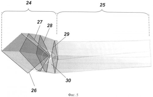
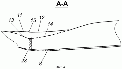
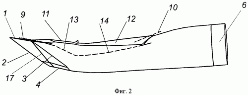
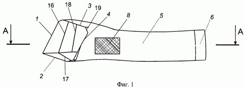
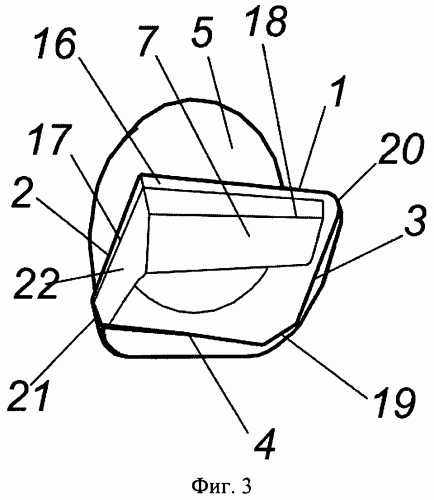
The invention is illustrated by drawings in which Figure 1 shows a variable supersonic air intake - view from below, in Figure 2 - adjustable supersonic air intake - side view Figure 3 - adjustable supersonic air intake - front view in Figure 4 - section A-A Figure 1, Figure 5 - Diagram of braking in a supersonic adjustable vents on the current flight mode, Figure 6 - a top view of a supersonic air intake and its control panel, Figure 7 - a side view of a supersonic air intake panel and its regulation; Figure 8 - section B-B in Figure 6.
Supersonic adjustable air intake includes the following:
1 - edge of the wedge brake 7,
2 - fixed edge of the wedge brake 22,
3, 4 - the edge of shell,
5 - channel inlet,
6 - a cylindrical section,
7 - wedge brake comprising an adjustable front panel 11,
8 - zone valves feeding possible location,
9 - pivot adjustable front panel 11,
10 - pivot adjustable rear panel 12,
11 - Adjustable front panel to maximize the throat (throat to minimum shown by the dotted line)
12 - Adjustable rear panel at maximum throat (throat to minimum shown by the dotted line)
13 - adjustable front panel 11 to the minimum position, the throat,
14 - Adjustable rear panel 12 is in the position of the minimum throat
15 - cross the gap between the front and rear panels of the regulated drain boundary layer
16 - line break between the first and second stages of the wedge brake comprising front adjustable panel
17 - line break between the first and second stages of the fixed wedge brake 22,
18 - line break between the second and third stages of the wedge brake comprising front adjustable panel
19 - cutting the dihedral angle formed by the jacket,
20 - rounding off the entrance to the place of articulation of the wedge brake comprising an adjustable front panel, and the shell,
21 - cutting the dihedral angle between the fixed airbrake 22 and sidewall,
22 - fixed wedge braking
23 - fold, subject to the additional transverse slit in the throat on a stationary wedge brake 22,
24 - supersonic diffuser (braking)
25 - subsonic diffuser
26 - oblique shock from the first stages of swept wedges
27 - oblique shock from the second stage swept wedges
28 - oblique shock from the third stage swept wedges
29 - NO direct shock wave,
30 - Bypass area of ​​oblique and normal shock wave to increase the range of air flow through the air intake, which is provided by its stable performance,
31 - the first stage of the wedge containing the adjustable front panel 11,
32, 33, 34 - the axis of rotation shutter 45,
35 - The intersection of the axes of rotation of the shutter 43 and the axis of the rear adjustable panel 12
36 - The intersection of the axes of rotation of the front and rear adjustable panels 11 and 12,
37 - the line along which is oriented transverse gap between the regulated panels 11 and 12,
38 - Drive back attachment points adjustable panel 12
39 - discharge openings in the rear adjustable panel 12
40 - pivot doors 23,
41 - on the back of tight CLADDING adjustable panel 12,
42 - control mechanism side swivel flap 23,
43 - traction drive adjustable front panel 11,
44 - loop channel
45 - blind,
46 - control gear compartment adjustable rear panel 12,
47 - profiled sides of the channel 5.
The main elements of the air intake can be identified 24 supersonic diffuser throat, subsonic diffuser 25, front 11 and rear 12 panels adjustable, pivoting around an axis, respectively 9 and 10.
Login form a front air intake - a parallelogram or a special case - a rectangle with arbitrary ratio of its height and the length of the corresponding side. You can do the trimming, such as 19 and 21, or round the corners, such as 20, enter the air intake, with the exception of the angle formed swept wedges. The edges of the inlet to lie in a plane oriented to the flow direction at an acute angle. Thus, all inputs are edge sweep.
Supersonic diffuser 24 is a flow deceleration system, consisting of a pair of swept wedges 7 and 22, forming a dihedral angle and the shell (3, 4 - the edge of shell). Arrow-shaped wedges of 7 and 22 have at least one stage, the number of steps in these wedges can be different. As an example, in Figure 1, 2, 3 and 4 show the air intake, which has an arrow-shaped wedge on one three stages, and the second - two. Fractures of the corresponding levels 16, 17, 18, swept wedges 7 and 22 intersect at a point on the line of intersection of the surfaces at the corresponding levels of wedges forming a dihedral angle. Sweep angles at each of the stages swept wedges may differ from the corresponding edge sweep angle of the wedge, as well as each other. The corners of the solution steps swept wedges are defined in the construction of the braking system of the conditions for the creation of each pair of corresponding levels wedges single oblique shock given intensity, ie uses the principles of gas-dynamic design (Shchepanovskaya VA Gutov BI "Gasdynamic designing supersonic air intakes." Nauka, Novosibirsk, 1993). On some levels swept wedges can be made perforation.
Sides as well as arrow-shaped wedges of 7 and 22, forms a dihedral angle. A characteristic feature of this orientation is the shell in which it further slows the flow, ie shell is not focused on the current lines for shocks of swept wedges. Undercut shell may be variable. In the dihedral angle formed by the jacket, the organization cutout of inlet air intake, and in the cowling can accommodate holes of arbitrary shape.
In the subsonic diffuser 25, there may be air valves feeding 8, providing access external flow air over the air intake in the subsonic diffuser 25. Leaf feeding 8 contribute to the characteristics of the air intake at low speeds (takeoff and flight conditions at high angles of attack).
Way to regulate air intake above is as follows. Front adjustable panel 11 comprising a step of swept wedges 7, except the first, rotates about the axis 9, located at the intersection of the first and second stage of the wedge 7. Response adjustable rear panel 12 is part of the subsonic diffuser 25 and is rotated around the axis of the spatial arrangement of 10. If the axis of the front nine adjustable panel set one, then a choice of orientation axis 10 adjustable rear panel, passing over its trailing edge, is determined from the intersection of the rear axle 10 panels with adjustable axis 9 adjustable front panel 11.
In regulating the air intake between the front 11 and rear 12 panels can be formed adjustable transverse slit 15 for draining the boundary layer. For the chosen way of defining the axes controlled panels transverse gap between them has a shape close to rectangular.
Front adjustable plate 11 is connected to the rear panel 12 by an adjustable rod 43.
In regulating the air intake front 11 and rear 12 panels adjustable, turning at the same time change their position in accordance with a given law. When turning the panels 11 and 12 changes throat area inlet, angle moving stages swept wedge 7, the size of the transverse slot 15 between the drain panels 11 and 12, with the side edges of the panels 11 and 12 are moved relative profiled flanks channel 47 without formation of cracks.
On a fixed wedge 22 sweepback in the throat can accommodate additional transverse slit drain boundary layer, closed flap 23. Flap control mechanism can be synchronized with the control panels 11, 12. For example, can be used kinematic mechanism 42 connecting rods and rocking through the rotary flap and adjustable front axle 9 panels 11.
These transverse cracks and perforations on the wedges help to improve the characteristics of the air intake at supersonic speeds.
On the rear panel 12 are adjustable discharge openings 39 to equalize the pressure in the channel and in the cavity above the adjustable rear panel 12. The cavity of the regulated panels 11, 12 is divided into two halves by a shutter 45, performed on a folder of partitions, and serves to separate the air from different pressure, which was in nadpanelnoe space through the perforation, cross the gap 15 between the drain adjustable panels and discharge openings 39. Shutter 45 is a hinged two flat panel - upper and lower. The top panel is hinged on the construction of 46 control gear compartment adjustable rear panel, bottom - hinged at the rear adjustable panel. To ensure the efficiency of kinematic shutter 45 of its axis of rotation 32, 33, 34 are oriented in space in such a way that they have a single point of intersection 35, which lies on the axis of rotation 10 adjustable rear panel 12.
Method of controlling intake with swept edges as follows.
At subsonic flight adjustable panels 11 and 12, the air intake is at maximum throat (retracted position, the main line in the figures), providing an area in which the channel no supersonic velocity.
At supersonic flight efficiency propulsion aircraft linked to the performance in the inlet flow deceleration. Supersonic flow in the inlet is inhibited in shock waves 26, 27, 28, resulting in the flow of wedges of the braking system. With the increase in supersonic flight speed adjustable panels 11 and 12 simultaneously deviate from the position corresponding to subsonic flight. Synchronicity deflection panels 11, 12 is provided by a mechanical connection between the front and rear adjustable panels 11, 12 with the rod 43. Thus, the mechanism by turning the adjustable rear panel 12, to be driven simultaneously adjustable front panel 11. When turning the adjustable front panel 11 in the direction of increasing angles of the intensity levels of the wedge flow deceleration in the shock of these steps. In this case, the back panel 12, turning reduces the area of ​​the throat inlet. Increasing the intensity of inhibition and reduction in area throat positively affect the performance air intake.
Deceleration of the flow to subsonic speed by a normal shock wave 29, which is located at the entrance to the air intake. Finally slowed to subsonic flow subsonic diffuser 25 and the motor.
Stable operation of the air intake on all flight and engine operation is ensured by the presence of air bypass 30 in oblique shocks, and Drainage of the boundary layer in the form of perforations on the steps of the wedges of the braking system and the transverse slot 15 between the front 11 and rear 12 adjustable panels.
Transverse slit 15 is formed at the position of the controlled panels 11 and 12, other than to clean. In the retracted position, the panels 11 and 12, the gap 15 is missing. This was achieved by selecting the orientation of the axes of rotation 9 and 10 adjustable panels in space in such a way that they have a point of intersection 36.
Draining of the boundary layer is possible and additionally through additional transverse slot located near the throat on a stationary wedge brake 22 (with fixed steps), and an adjustable flap 23.
Additional lateral gap opened in the main supersonic flight conditions at the position of the controlled panels 11 and 12, other than to clean. When retracted position adjustable panels 11 and 12 of the additional transverse slit closed doors 23.
Panels simultaneously with the release of the shutter starts to open 45, separating the air that enters the space above the rear adjustable panel 12 through the discharge opening 39, and the air that enters the space above the front panel adjustable through perforations 11 and 15 cross the gap between regulated drain panels 11 and 12.
The proposed control method provides a high internal gas dynamic characteristics inlet configuration that simultaneously reduces its radar signature by a parallelogram shape from the front entrance and the presence of a sweep of all input edges and steps airbrake. Select the orientation of the mentioned parts that form, to orientate their design to the direction of X-ray laser irradiation so as to deviate from this trend reflected the design of the radio, and to exclude the presence of corner reflectors.

Claim
1. Method of control of a supersonic air intake, which is carried out change in the area and the position of the throat shocks, characterized in that the change in the area of ​​the throat and the position of shocks by simultaneously turning adjustable front panel, the rotation axis coincides with the line of intersection of the first and second stage of one of the arrow-shaped wedges that is not perpendicular to the oncoming flow, and an adjustable rear panel, the axis of rotation of which is located in the area of ​​the rear edge of the rear panel, controlled and directed from the condition of having a point of intersection with the axis of rotation of the front panel, adjustable, thus when you turn the front and rear panels of adjustable lateral edges move relative profiled flanks channel without forming gaps between them.
2. The method according to claim 1, characterized in that when you turn the front and rear panels of controlled orientation transverse slit between the top view does not change, and its position coincides with the line passing through the point of intersection of the axes of the front and rear adjustable panels, with the gap has a shape similar to a square in every possible position adjustable panels.
3. The method according to claim 1, characterized in that when you turn the front and rear panels of controlled panel shutters rotate relative to the axis of its rotation and oriented in such a way that a common point of intersection between the axis of rotation and an adjustable rear panel.
4. The method according to claim 1, characterized in that when you turn the front and rear panels of regulated changes position kinematically related rotary wing covering the transverse slot on the unregulated airbrake in the throat.
 

Attachments

  • 2733950.gif
    2733950.gif
    6.8 KB · Views: 51
  • 2733949.gif
    2733949.gif
    17.7 KB · Views: 50
  • 2733948.gif
    2733948.gif
    24.4 KB · Views: 45
  • 2733947.jpg
    2733947.jpg
    123.9 KB · Views: 561
  • 2733946.gif
    2733946.gif
    15.8 KB · Views: 556
  • 2733945.gif
    2733945.gif
    15.5 KB · Views: 567
  • 2733944.gif
    2733944.gif
    16.3 KB · Views: 580
  • 2733942.gif
    2733942.gif
    16.9 KB · Views: 605
Fixed-wing antenna array (link posted earlier by SaintKatanaLegacy)

http://www.findpatent.ru/patent/243/2439758.html

The invention relates to antenna technology, in particular to a phased array antenna are located on board aircraft. The technical result is a reduction in the influence of microwave devices placed on the strength characteristics of the aircraft, reducing thermal loads on the active microwave devices, improved shielding compartments thrust wing leading edge, increasing reliability and improving the characteristics of the emission array. Aviation-array contains n emitters, mounted on the front of the nose of an airplane wing, covered with removable cowl and active microwave devices, inputs and outputs are connected to the respective emitters, and the outputs to the inputs of inputs-outputs of the summation. The radiators are installed in the movable part of the wing leading edge is perpendicular to the transverse axis front edge, active microwave devices and circuits are placed in a fixed sum wing root in the compartments between the power and the transverse dielectric diaphragms connected to the cooling circuit plane. In the airborne antenna array transducers can be located in the left-and right-moving parts of the wing leading edge, and active microwave devices and circuits in the fixed sum the left and right wing root. Wing compartments that contain active microwave devices and circuits summation, covered with removable absorbing materials. 3 Description: f-ly, 1 ill.
The invention relates to antenna technology, in particular to a phased array antenna are located on board aircraft.
Known "Airborne scanning antenna system with inter-element insulators» (US 4186400, publ. 29/01/1980) established under the wing fairing, which includes arrays based emitters Uda-Yagi along the wing leading edge. The emitters are placed in the horizontal and vertical planes. The disadvantages of such an antenna system is cumbersome design radiators and the complexity of their location, the need for additional resources for mounting the elements of radiators on the fairing and in the space under the cowl.
Also known "Airborne scanning antenna system based on a linear array of emitters such as Yagi» (US 4336543, publ. 06/22/1982) established under the wing fairing and containing a linear array antenna consisting of emitters such as Yagi-Uda, located in a horizontal plane. The disadvantages of such an antenna system is the large dimensions, the need for the design of the fairing set shear walls for mounting the radiators, which can degrade the radiation antenna array.
In addition, the well-known "linear array antenna with adjustable radiation suppressor E-plane» (US 5151707, publ. 29/09/1992) installed under the fairing of an airplane wing, consisting of printed radiators, placed on a flat dielectric, which are located along the leading edge of the wing, and mounted on a metal screen, and the back of the screen to suppress the rear light is bent and attached to the front of the nose of an airplane wing. The disadvantages of such an antenna system is the large dimensions, mounting complexity of radiators on the screen inside the fairing.
Is close to the technical nature of a "modular array» (US 4749997, publ. 07/06/1988) conformally mounted on the aircraft and including n sublattices. Each sublattice is composed of n (4) horizontal polarization radiators placed under the cowl and installed parallel to the wing leading edge and before the conducting screen, n (4) active microwave devices, the I / O through the transformers are connected impedance transducers, as well as the scheme summation. Active devices installed at the rear side of the conductive screen, and cut slits in the screen through which the emitters are connected to active devices, placed on the back of the conductive screen (the front of the leading edge of the wing). Also on the back side of the front of the set of summing circuit to which the cables are connected by microwave active devices.
To provide the necessary direction antenna array under the fairing also installed dielectric tube, located along the length of the antenna array along the windshield and fixed dividers that separate one from the other sublattice, and certain parts of the tube are covered with a conductive layer. Fairing each sublattice leans hinged to allow access to the rear of the front of the nose wing.
The disadvantages of such an antenna array is low strength properties due to lack of integrity of the fairing and the multitude of through-holes in the front of the nose wing. With active microwave devices on the back of the front of the wing leading edge to them are increased requirements for climatic influences. Dividers that separate modules array, degrade the properties of the radiation antenna array.
The technical result of the proposed antenna array is to reduce the influence of microwave devices placed on the strength characteristics of the aircraft, reducing the thermal loads on the active microwave devices, improved shielding compartments thrust wing leading edge, increase reliability and improve the performance of radiation antenna array by placing the blocks in the left and right side wing and connecting them to the cooling circuit plane.
Summary of the utility of the model is that the aviation-array contains n emitters, mounted on the front of the nose of an airplane wing, covered with removable cowl and active microwave devices, inputs and outputs are connected to the respective transmitters and outputs Inputs with input-output circuits summation.
Novel features of the claimed technical solution is that the radiators are installed in the mobile part of the wing leading edge perpendicular to the transverse axis of the front edge of it, active microwave devices and circuits are placed in a fixed sum wing root in the compartments between the force and the transverse dielectric diaphragms connected to the cooling circuit plane. In a statement airborne antenna array transducers can be located in the left-and right-moving parts of the wing leading edge, active microwave devices and circuits in the fixed sum the left and right wing root, and wing sections that contain the active microwave devices and circuits summation, covered with removable absorbing material.
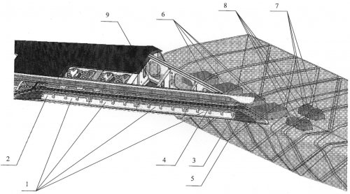
The drawing shows a variant of the proposed placement of equipment airborne antenna array in a fixed wing root and the movable part of the wing leading edge.
Aviation-array consists of one of the radiating system, made ​​of two separate radiators are installed on three panels made ​​of durable and lightweight metal. The whole structure of the system is filled with radio waves radiating penokompaundom having a low dielectric constant ( less than 1.1) and imparting additional strength and design elektrogermetichnost. Radiating system 1 mounted on the front of the wing leading edge 4 and closes removable radio waves fairing 5, which is a part of the wing leading edge. The entire length of the fairing is installed parallel to the radiator diaphragm dielectric material fairing, providing its mechanical strength.
Active microwave devices (such as two-way modules) 6, adding unit 7, unit distribution and phasing of 8 are located in the wing root compartments. Disassembly and assembly of the equipment in the mobile part of the wing leading edge and the fixed equipment in the root of the wing fairing provides readout radiotransparent 5, as well as access through manholes 9.
Accommodation active microwave devices 6 and 7 in Holmgreen compartments fixed wing reduces thermal load on the blocks airborne antenna array, which in turn increases the reliability of its use of forced cooling. The use of whole fairing with a transverse aperture throughout its length can improve the strength characteristics of the wing leading edge and the emission characteristics of the antenna array.
Closed compartment thrust wing leading edge radar absorbing materials can escape these sections and blocks of microwave radiation for smooth low-frequency control devices. Placing emitters perpendicular transverse axis of the wing leading edge and securing them with metal panels can get a vertically polarized radiation airborne antenna array and install it in thin socks and small wings. Placing the antenna array in the right and left sides of the wing significantly improves its performance.
Thus, the proposed aviation-array process is simple allocation scheme on site, thereby achieving compactness, simplicity and reliability of the design and improvement of its radio characteristics.

Claim
1. Aviatic array containing n emitters, mounted on the front wall of the nose of an airplane wing, covered with removable cowl and active microwave devices, inputs and outputs are connected to the respective transmitters and outputs Inputs - with input-output summation scheme, wherein the transducers mounted in the movable part of the wing leading edge perpendicular to the transverse axis of the anterior edge, active microwave devices and circuits are placed in a fixed sum wing root in the compartments between the force and the transverse diaphragms connected to the cooling circuit plane.
2. Aviation-array antenna of claim 1, wherein the emitters are located in the left-and right-moving parts of the nose wing.
3. Aviation-array antenna according to claim 1, characterized in that the active microwave devices and circuits are located in the fixed sum the left and right wing root.
4. Aviation-array antenna of claim 1, wherein the wing sections that contain the active microwave devices and circuits summation closed absorbing materials.
 

Attachments

  • 2534491.jpg
    2534491.jpg
    1 MB · Views: 100
Aircraft integral aerodynamic layout

http://www.findpatent.ru/patent/244/2440916.html


The invention relates to a multi-mode aircraft. Aircraft integral aerodynamic layout comprises a fuselage (1) with flow (2), wing, bracket (3) is smoothly conjugate to the fuselage (1), all-moving horizontal tail (4), all-moving vertical tail (5). The middle part of the fuselage is made flattened and formed longitudinally on a set of airfoils. Engines are located in nacelles (6), separated from each other horizontally, and the motor axis oriented at an acute angle to the plane of symmetry of the aircraft on the flight direction. Influx (2) includes guided rotary part (8). The invention aims to reduce the radar cross section, increasing maneuverability at high angles of attack and aerodynamic efficiency at supersonic. Description: 9 f-ly, 4 ill.
The invention relates to a multi-mode aircraft operated at supersonic and subsonic flight, in a wide range of altitudes. Preferred area of ​​application of the invention - multimode SUPER airplanes cruise at supersonic speeds and low level radar signature.
Creating aircraft capable to perform tasks in a wide range of altitudes and flight speeds, have the capacity and super maneuverability, while having a low radar signature wavelengths is a difficult technical challenge.
For aerodynamic design of the airplane special requirements to maximize aerodynamic efficiency (lift and reduce drag force) at subsonic and supersonic flight speeds, ensuring controllability at ultra-low speeds. To the external form of the airframe special requirements to reduce radar visibility. All of these requirements are contradictory, and an airplane that meets such demands, is a compromise.
Known aircraft, adopted as the closest analogue, which combines features of multi-mode supersonic aircraft possessing super-maneuverability and low radar signature. Known aircraft made by the normal balancing scheme with tselnopovorotnym horizontal tail surface, providing control of the plane in the longitudinal channel (pitch) in all flight regimes. In addition to control of the aircraft in the longitudinal channel all-moving horizontal tail is used to control the aircraft in roll by differential mode rejection at supersonic flight.
Trapezoidal wing has a negative sweep of the trailing edge, which allows for the high values ​​of the lengths of the chords in the root part to reduce the relative thickness of the wing in the area at high absolute thickness of the wing. This solution is aimed at the same time to reduce the wave drag at transonic and supersonic flight speeds, as well as to increase the supply of fuel in the wing tanks.
The mechanization of the wing leading edge is presented adaptive turning toe, used to increase the value of aerodynamic control in subsonic cruise, to improve the flow of the wing at high angles of attack, and to improve the maneuverability characteristics.
The mechanization of the trailing edge of the wing is represented by:
flaps that are used to control lift at takeoff and landing, as well as to control the aircraft in roll in the modes of trans-and supersonic flight;
ailerons, used to control the aircraft in roll at takeoff and landing.
Two consoles vertical tail, consisting of keels and rudders, provide stability and control in the traveling channel and the air brake. Management in the traveling channel provides common-mode rejection rudders and air braking - differential rudder deflection. Plane chords consoles vertical tail turned down from the vertical at an acute angle, thereby reducing the radar signature aircraft lateral hemisphere.
Engine air intakes are located on the sides of the fuselage. Inlet to the oblique plane in two dimensions, which allows for a steady stream of air entering the engines in all flight conditions, including at high angles of attack.
Aircraft engines are located in the tail section, next to each other that the location of air intakes on the sides of the fuselage allows for curved air intake ducts. This solution is used to reduce radar signature engine, and as a result, the aircraft as a whole in the forward hemisphere, due to screening of the engine compressor design air intake ducts. Deflected in the vertical planes wing "plane" jet nozzles allow for thrust vector control, which, in turn, allows for the possibility of control of the aircraft in the pitch channel for low-speed flight regimes, and provides supply diving moment at supercritical angles of attack with tselnopovorotnym horizontal tail surface. Such a solution provides a feature super maneuverability (Lockheed Martin F/A-22 Raptor: Stealth Fighter. Jay Miller. 2005).
As disadvantages of the aircraft, you can specify the following:
- The inability to control roll and yaw channels when flying at low speeds, because the engines are located close to each other, which is not sufficient to create a control point;
- The engines next to each other making it impossible location in the fuselage cargo compartments;
- Curved shape of air intake ducts requires increasing their length, and thus the mass of the airplane;
- The inability to ensure the "gathering," an aircraft with supercritical angles of attack on system failure exhaust nozzle control motors;
- The use of fixed keels with rudders requires an increase of the required area of ​​the vertical tail for directional stability at supersonic flight conditions, which leads to an increase in the mass of feathers, and, consequently, the aircraft as a whole, as well as an increase in drag.
The technical result for aim of the invention is to create an aircraft that has a low radar signature, super-maneuverability at high angles of attack, high aerodynamic efficiency at supersonic speeds and at the same time, maintain the high aerodynamic efficiency at subsonic, the possibility of placing in the inner compartments of bulky cargo .
The inventive in that plane integral aerodynamic layout containing the fuselage, wing, the console is smoothly conjugate to the fuselage, horizontal and vertical tail, twin powerplant, the fuselage is equipped with the influx, located at the entrance to the engine intakes and include managed superstructure, the middle part of the fuselage is made flattened and formed longitudinally on a set of aerodynamic shapes, engine nacelles are spaced apart horizontally, and the motor axis oriented at an acute angle to the plane of symmetry of the aircraft on the flight direction.
In addition, the vertical tail tselnopovorotnym satisfied with the possibility of common mode and differential deflection.
In addition, all-moving vertical stabilizers mounted on pylons located on the side of tail boom fuselage, while on the front of the pylons are blowing the engine compartment air intakes and air conditioning heat exchangers.
In addition, the horizontal tail tselnopovorotnym satisfied with the ability to reject common-mode and differential.
In addition, the jet engine nozzle configured to reject common-mode and differential.
In addition, the inlet to the engine located on each side of the forward fuselage behind the cockpit, with the lower edge of the inlet to the engine located below the fuselage.
In addition, the inlet to the engine is made in two oblique planes - with respect to the longitudinal vertical plane and transverse planes.
In addition, the plane chords consoles all-moving vertical tail deflected from the vertical plane at an acute angle.
In addition, the front edges of the turning part influx, wing panels and horizontal tail are made parallel to each other.
In addition, the rear edge of the wing and horizontal tail are made parallel to each other.
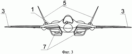
The invention is illustrated by drawings in which Figure 1 shows a plane integral aerodynamic layout - top view Figure 2 - aircraft integral aerodynamic layout - side view in Figure 3 - the aircraft integral aerodynamic layout - front view in Figure 4 - View A Figure 2.
Drawings on the positions designated:
1 - the fuselage,
2 - influx fuselage
3 - wing,
4 - Console tselnopovorotnogo vertical tail (CSSC)
5 - Console tselnopovorotnogo horizontal tail (TSPVO)
6 - nacelle engines
7 - engine air intakes,
8 - driven rotary influx of the fuselage,
9 - rotary wing socks,
10 - ailerons,
11 - flaps,
12-pylon CPVO,
13 - blow the engine compartment air intakes and air conditioning heat exchangers,
14 - rotating jet engines
15 - sections of jet engines rotary nozzles,
16 - axis of rotation of the rotary nozzle engines
17 - the plane of rotation of the rotary engine nozzles.
Aircraft integral aerodynamic layout is a monoplane, made by the normal balancing scheme, and contains fuselage 1 with flow 2, wing arm 3 is smoothly conjugate to the fuselage 1, the all-moving horizontal tail (hereinafter - CSSC) 4, all-moving vertical stabilizers (hereinafter - TSPVO ), 5 twin powerplant, the engines of which are located in nacelles 6. 6 engine nacelles are spaced apart from each other horizontally, and the motor axis oriented at an acute angle to the plane of symmetry of the aircraft in the flight direction.
The influx of two fuselage 1 is located above the air inlets 7 motors and includes managed revolving portion 8. Swivel 8 influx two leading edges are flattened middle of the fuselage 1.
Console 3 wings, blending with the fuselage 1, equipped with mechanization leading and trailing edges, which includes turning socks 9, ailerons and flaps 10 11.
CSSC 4 installed on the sides of the fuselage tail boom 1. TSPVO 5 installed on pylons 12, mounted on the side of tail boom fuselage 1. At the front of the pylons 12 are 13 air intakes and engine compartment heat exchanger blowing air conditioning system. Setting TSPVO 5 pylon 12 increases the shoulder supports TSPVO axis 5, which, in turn, reduces reactive loads on the power components frame airframe and therefore lose weight. The increase in the shoulder supports TSPVO 5 due to the fact that the upper bearing is located inside the pylon 12, which, in fact, increased the shoulder supports (distance between supports). In addition, 12 are pylon fairing hydraulic TSPVO CSSC 5 and 4, which allows by moving hydraulic beyond the fuselage 1 increase cargo capacity between the pods 6.
Inlet to 7 motors located on each side of the forward fuselage 1, with the cabin crew, under the rotating parts 2 and 8 influx made beveled in two planes - with respect to the longitudinal vertical plane and transverse planes, with the lower edge of the inlet to the engine is below 7 fuselage 1 .
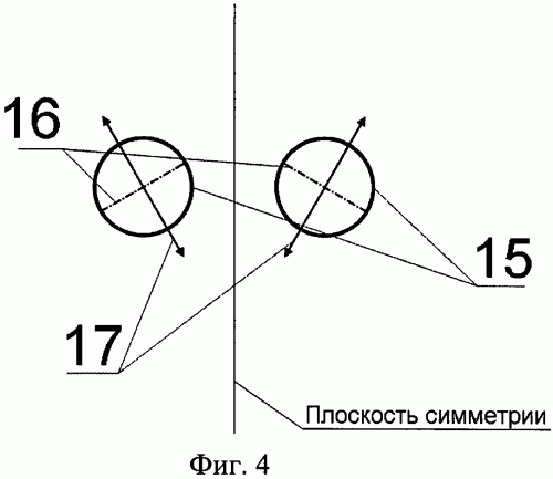
Engines equipped with rotating axisymmetric jet nozzle 14, which is a turn in planes oriented at an angle to the plane of symmetry of the aircraft. Rocket engine nozzle 14 configured to reject common-mode and differential for control of the aircraft by moving the thrust vector. Scheme targeting rotary jet nozzles 14 shown in Figure 4, which displays: 15 slices of jet nozzles 14 rotary engines, the axis of rotation 16 jet nozzles 14 rotary engines and the plane of rotation of 17 rotary jet nozzles 14 engines.
The aircraft has a low radar signature wavelengths, and by providing super maneuverability - perform tasks in a wide range of altitudes and flight speeds.
Increase aerodynamic efficiency at subsonic flight speeds achieved by the formation of the middle part of the surface of the fuselage 1 (except for the nose and tail parts) for the longitudinal (in longitudinal section) set of aerodynamic profiles and use the rotary parts 8 influx 2, which allows you to include one in the fuselage create lift.
The high level of aerodynamic efficiency at subsonic flight speeds achieved by the use of the wing with 3 consoles trapezoidal shape in plan with a great sweep of the leading edge, a large contraction, with the larger length of the root of the chord and a low value end of the chord length. Such a set of solutions allows for large values ​​of the absolute height of the wing, especially in the root, to realize the small values ​​of the relative thickness of the wing, which reduces the value of the drag force of growth occurring in the transonic and supersonic speeds.
CSSC 4 provides the ability to control the aircraft in the longitudinal channel with common-mode rejection and cross-channel with differential deviation of trans-and supersonic speeds.
TSPVO 5 offers stability and control in the traveling channel at all flight speeds and provides the function of the air brake. Stability at supersonic flight speeds in low areas of the required static deflection is provided by consoles TSPVO 5 entirely. In the event of disturbance of the atmosphere or in a gust of wind carried the traveling channel common-mode rejection consoles TSPVO 5 towards countering disturbances. This solution allows to reduce the area of ​​feathers, reducing thus the weight and resistance of feathers and flight in general. Management in the traveling channel is carried out in-phase rejection TSPVO 5, and air braking - for differential rejection TSPVO 5.
High lift system is used to provide control lift and roll. Rotary wing sock 9 is used to increase the critical angle of attack and ensure bumpless flow wing to fly "on the envelope polar" on takeoff, landing, maneuvering and cruising subsonic flight. Ailerons 10 are designed to control the aircraft in roll at a differential deviation at takeoff and landing. Flaps 11 are intended to control the increment of lift when common-mode rejection down on takeoff and landing, for roll control for differential rejection.
Rotating part 8 influx two fuselage 1 with downward deviation reduces the area of ​​the planned projection of the fuselage in front of the center of mass of one plane, which contributes to the creation of excess time on a dive during the flight at angles of attack of about 90 degrees. Thus, in the event of failure of the control system of jet nozzles 14 provides a migration path to flight mode at supercritical angles of attack to fly at low angles of attack without the control of the aircraft by A thrust engines. Simultaneously rotating part 8 influx 2 is the front edge of mechanized influx two fuselage 1. If you deviate Swivel 8 2 down on the influx of cruise phase it performs functions like turning a sock 9 wing.
The use of side air intakes located under the rotating part of the influx of 8 2, ensures stable operation of the engine in all modes of the airplane, in all positions by aligning the incoming flow at high angles of attack and slip.
The engines in isolated nacelles 6 allows you to place between a compartment for bulky cargo. Turn around time for parrying if one of the engines of their axes are oriented at an acute angle to the plane of symmetry of the aircraft so that the thrust of the engine took to the center of mass plane. This arrangement of motors, together with the use of rotary jet nozzles 14, which is a turn in a plane inclined at an acute angle to the plane of symmetry of the aircraft allows the control of the aircraft with thrust vectoring engines - in the longitudinal, transverse and travel channels. Management in the longitudinal channel with common-mode rejection is turning jet nozzles 14, creating a pitching moment about the center of mass of the aircraft. Control of the aircraft in the lateral channel is by differential deflection of jet nozzles 14, creating at the same time rolling moment and yawing moment, with rolling moment countered deviation aerodynamic controls (ailerons and flaps 10 11). Control of the aircraft in the transverse channel the deviation in the differential rotary jet nozzles 14, creating a rolling moment about the center of mass of the aircraft.
Reduction of radar cross section aircraft achieved through a combination of design and technological activities, which include, in particular, is shaping contours of the airframe, which includes:
- Parallel to the front edge of the rotary 8 influx 2, 3 consoles wing and horizontal tail 4, parallel to the rear edges of the console 3 wing and horizontal tail 4, which allows us to localize the peaks reflected from the bearing surfaces airframe electromagnetic waves and thus reduce the overall level of radar visibility of the aircraft in the azimuth plane;
- Orientation of the tangent to the contour of the fuselage cross-section, including the cockpit, at an angle to the vertical plane (the plane of symmetry of the airplane), which contributes to the reflection of electromagnetic waves incident on the airframe from side angles, the upper and lower hemisphere, thus reducing overall radar signature aircraft lateral hemisphere;
- Skewness inlet to the engine in two planes - vertical relative to the longitudinal and transverse planes airplane can reflect electromagnetic waves arriving at the inlet to the vehicle from the front and side angles, away from the radiation source, thereby reducing the overall radar signature aircraft in these angles .

Claim
1. Aircraft integral aerodynamic layout containing the fuselage, wing, gently console which involve the fuselage, horizontal and vertical stabilizers, twin-engine propulsion, wherein the fuselage is equipped with the influx, located at the entrance to the engine air intake and including controlled rotary part, middle part of the fuselage is made flattened and formed longitudinally on a set of airfoils, engine nacelles are spaced apart from each other horizontally, and the motor axis oriented at an acute angle to the plane of symmetry of the aircraft on the flight direction.
2. The aircraft of claim 1, characterized in that the vertical stabilizer with the ability to complete tselnopovorotnym common mode and differential deflection.
3. The aircraft of claim 2, wherein the all-moving vertical stabilizers mounted on pylons located on the side of tail boom fuselage, while on the front of the pylons are blowing the engine compartment air intakes and air conditioning heat exchangers.
4. The aircraft of claim 1, characterized in that the horizontal stabilizer with the ability to complete tselnopovorotnym common mode and differential deflection.
5. The aircraft of claim 1, characterized in that the jet engine nozzle configured to reject common-mode and differential.
6. The aircraft of claim 1, characterized in that the inlet to the engine located on each side of the forward fuselage for the cabin crew, the lower edge of the inlet to the engine located below the fuselage.
7. The aircraft of claim 1, characterized in that the inlet to the engine is made in two oblique planes - with respect to the longitudinal vertical plane and transverse planes.
8. The aircraft of claim 1, wherein the plane chords consoles all-moving vertical tail deflected from the vertical plane at an acute angle.
9. The aircraft of claim 1, characterized in that the front edges of the turning part influx, wing panels and horizontal tail are made parallel to each other.
10. The aircraft according to claim 1, characterized in that the rear edge of the wing and horizontal tail are made parallel to each other.
 

Attachments

  • 2544842.gif
    2544842.gif
    12.5 KB · Views: 74
  • 2544841.gif
    2544841.gif
    15 KB · Views: 72
  • 2544840.gif
    2544840.gif
    10.6 KB · Views: 74
  • 2544838.gif
    2544838.gif
    26.9 KB · Views: 69
multi-mode highly maneuverable aircraft INTEGRATED aerodynamic design

http://www.findpatent.ru/patent/240/2400402.html

The aircraft has a fuselage, in which the average of (2) involves gently swept wing panels (3), the head (1) and tail (6), where the all-moving vertical stabilizers (4) and all-moving horizontal tail (5). At the head of (1) the fuselage is light (10). The fuselage has increased the width of the cross section and is made up of the airfoil height allows you to place the main cargo compartment in the fuselage between the air intakes. The invention is directed to an even distribution of air and increase the load bearing properties of the fuselage. 10 ill.
The invention relates to a multi-mode aircraft operated at supersonic and subsonic flight in a wide range of altitudes. Preferred area of ​​application of the invention are multi-mode SUPER airplanes cruise at supersonic speeds and low level of visibility in the radar (radar) range.
Known in the art aircraft integral aerodynamic layout containing a single lifting fuselage, where the middle part of the fuselage smoothly interfaced with swept wing panels, the head of the fuselage and the tail (RU 2140376 C1).
As disadvantages of the aircraft should indicate the following. In a plane distribution of goods on the external load does not achieve a small degree of radar visibility and high aerodynamic characteristics at supersonic flight conditions.
Due to the complex technical solutions applied in this arrangement, and, above all, an integrated aerodynamic configuration of the fuselage, the aircraft has a high value of the aerodynamic efficiency at subsonic flight conditions.
The technical result for aim of the invention is to create a small plane had RL degree visibility, super-maneuverability at high angles of attack, high aerodynamic efficiency at supersonic speeds and at the same time, maintain the high aerodynamic efficiency at subsonic regimes.
This technical result is achieved by a multi-mode highly maneuverable aircraft integral aerodynamic layout containing the fuselage, the middle part of which involves gently swept wing panels, the head of the fuselage and tail, all-moving vertical and all-moving horizontal tail, located in the rear fuselage, the average integrated with the fuselage center section of the wing and made flattened in a vertical direction, and its outer surface in the longitudinal direction formed by a set of aerodynamic profiles with high building heights, providing accommodation within the fuselage built cargo compartments, the upper surface of the fuselage to pair with the outer surface of the lamp and the expanding in the area from light to the rear fuselage with decreasing curvature.
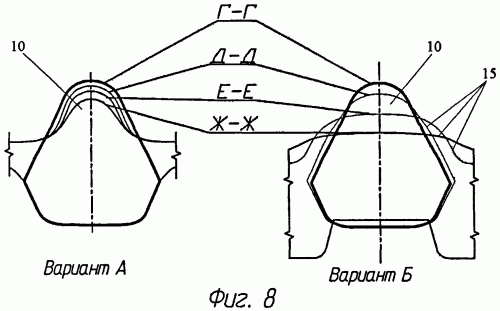
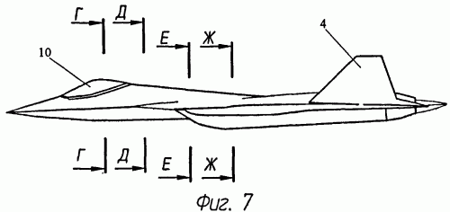
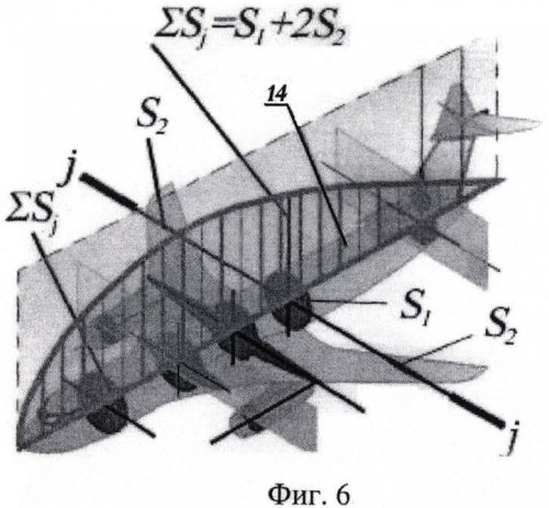
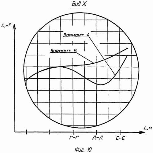
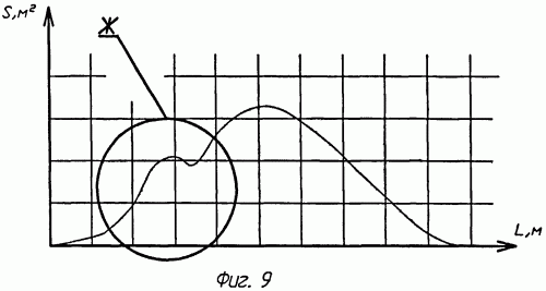
The invention is illustrated by drawings in which Figure 1 shows a plane at the plan view, Figure 2 - cross section AA of Figure 1, Figure 3 - section B-B Figure 1, Figure 4 - section B In Figure 2, Figure 5 - section D-D 2; Figure 6 - Rotation of least resistance (the body Siirsa-Haack) Figure 7 - seats fuselage cross-section, Figure 8 - transverse section 7; Figure 9 - schedule fuselage cross-section, Figure 10 - bigger portion of the graph of the cross-sections of the fuselage behind the canopy.
The aircraft comprises a fuselage, in which the middle part two seamlessly interfaced with swept wing panels 3, the head part 1 fuselage and tail section 6. The aft fuselage six all-moving vertical 4 and all-moving horizontal tail 5. At the head of one fuselage is light 10.
In terms of aerodynamic design aircraft has the following features: a wide lifting fuselage and smoothed graph cross-sectional areas at the site of the aircraft cockpit.
The fuselage has increased the width of the cross section (Fig. 1, 2) and is made up of airfoil 11, 12, 13 (3, 4, 5), the height of which can accommodate the main cargo compartment 9 in the fuselage of the aircraft (Figure 2, 3) between the air inlets 8 and provides the necessary headroom to accommodate the side cargo doors 7 (2, 4).
In addition to space for cargo, due to the flattened layout is uniform distribution of air over the surface of the load and increase the airframe fuselage lift properties in terms of creating lift, which preserves the aerodynamic characteristics of the aircraft as a whole with a smaller wing area,
In addition, such a flattening of the fuselage reduces the effective area of ​​the radar in the most likely areas of exposure: side and front projection plane.
Graphics Alpha cross-sectional areas at the site of an airplane cockpit can improve the aerodynamic performance of aircraft by reducing drag.
Besides the general theoretical outline on aerodynamics of the aircraft and drag affects the relative position and inter-linkages between aircraft parts. To estimate the drag on the mutual influence (interference), typically used in the design space (Figure 6), which is as follows: in order to reduce the resistance, the diagram of 14 cross-sectional areas S j of all elements of the plane along the length of the aircraft must comply with orthographic drawing equivalent body rotation of least resistance (cigar-shaped body of high aspect ratio, the so-called body Siirsa-Haack).
The prior art in the design of aircraft used scheme linking light and fuselage, shown in Figure 8 (A - a common scheme), which is characterized by the fact that the cross-sectional area is reduced by the portion of the light to the rear. Schedule of areas for the scheme has a pronounced deviation from the body Siirsa-Haack in the light (Figure 9 and Figure 10, section A).
To improve aerodynamics a scheme linking, which consists in the fact that the upper surface 15 of the fuselage is expanding in the area from the lamp 10 to the fuselage tail section 6, offsetting reduction in the area of ​​cross-sections (Figure 8, B - invented scheme), resulting in smoother "failure "on the graph area of ​​the pilot lamp, characteristic of traditional aircraft integral aerodynamic layout. The curve on the graph area is close to the optimal shape, which indicates an improvement of aerodynamic characteristics (Figure 10, section B) by reducing drag.

Claim
Multimode highly maneuverable aircraft integral aerodynamic layout containing the fuselage, the middle part of which involves gently swept wing panels, the head of the fuselage and tail, all-moving vertical and all-moving horizontal tail located at the rear of the fuselage, wherein the middle part of the fuselage is integrated with the center section of the wing and made flattened in a vertical direction, and its outer surface in the longitudinal direction formed by a set of aerodynamic profiles with high building heights, providing accommodation within the fuselage built cargo compartments, the upper surface of the fuselage to pair with outside light and expanding the area from light to the rear fuselage with decreasing curvature.
 

Attachments

  • 2147168.gif
    2147168.gif
    21.2 KB · Views: 52
  • 2147167.gif
    2147167.gif
    10.8 KB · Views: 49
  • 2147166.jpg
    2147166.jpg
    171.2 KB · Views: 45
  • 2147165.gif
    2147165.gif
    7.1 KB · Views: 47
  • 2147164.gif
    2147164.gif
    5 KB · Views: 41
  • 2147163.gif
    2147163.gif
    6.2 KB · Views: 42
  • 2147162.gif
    2147162.gif
    9.2 KB · Views: 42
  • 2147161.gif
    2147161.gif
    19.9 KB · Views: 41
Information Control System aircraft

http://www.findpatent.ru/patent/239/2392586.html

The invention relates to the field of Aerospace Instrumentation, namely the command and status indication of the aircraft (LA). Technical result - enhanced functionality. To achieve this result, information and control system aircraft contains information-control field, on-board digital computer system, input-output unit, and exchange control, block the formation of flight and navigation options, database flight mission. Additionally, the system contains a power hub signal generation unit and integration for the display and reception of control actions, the control and monitoring obschesamoletnogo equipment, electronic control unit resistance, low-altitude flight software block, block group providing air navigation, the control account in the means of objective control and a control regimes. 3 Description: f-ly, 1 ill.
The invention relates to the field of aviation, namely the command and displays.
Known sighting and navigation equipment complex multifunctional aircraft (RF Patent 2282156), which contains interconnected input-output channel on-board data exchange an indicative information management system pilot, an indicative information management system of the operator, complex navigation and piloting of the complex surveillance and attack tools management system by means of resistance, on-board computer system, including interconnection of input-output on line computer information sharing computational logic modules, integrated database, navigation and formation flight parameters, formation attack and navigation options, forming the display information, input-output and control information exchange the other input-output is the input-output onboard computer system. In addition, the complex is equipped with the introduction of the onboard computer system computational logic modules mutual correction of navigation and impact parameters, mutual fusion navigation and impact parameters, the formation of the state of the aircraft available options, simultaneous co-ordinated use of countermeasures, input-output related to each other and computationally logic modules integrated database, navigation and formation flight parameters, input-output and control information exchange, form of attack and flight parameters and the formation of the information displayed on line computer information exchange.
Known sighting and navigation system multifunctional aircraft carrier-based and land-based (RF Patent 2276328), which contains the input-output interconnection via information exchange set multifunction indicators, head-up displays, television camera zakabinnogo review, of the operational management, a set of surveillance and attack tools with navigation and navigation tools, portable media source data management system by means of resistance, the computer system, including interconnection of input-output on line computer information sharing computational logic modules, integrated database, navigation and formation flight parameters, formation attack and navigation options, forming information is displayed, input-output and control information exchange, input-output of the last of which is an input-output computer system. The complex is also equipped with the introduction of the computer system computational logic modules virtual machine control, inertial-satellite mode of formation of the relative coordinates of aircraft position, exhibitions at the exchange rate on the mobile and fluctuating basis, the optimal use of resources, interconnected with each other and with computational logic modules combined base data, navigation and formation flight parameters, the formation of attack and flight parameters for the formation of information displayed, input-output and control information exchange on line computer information exchange.
The closest analogue is information and control complex aircraft (LA) (RF Patent 2232376), which includes interconnected input-output data exchange via information-control field, on-board digital computer system comprising interacting on computer information exchange channel input-output unit and exchange control, block the formation of flight and navigation options, database flight mission.
As disadvantages of the closest analogue, you can specify the following:
- The complex consists of functionally complete systems rather autonomously solve all the problems of the information for its sensors to output control information system to display signals in the control system of the aircraft and weapons. As a result, each of the information system has its own algorithms solving the problem, not taking into account information from other systems, an autonomous channel output to the display, its controls. Integrated use of information from other systems, with the exception of the problem of targeting one of the other, and the correction of satellite navigation systems (GPS) and radar (SAR), is practically implemented;
- The lack of information available on analog lines, so that blocks of ECC have limited information;
- The lack of display screen embedded processor designed for solving computational problems in addition to the formation of the display makes the complex actually nerabotospobnym failure VSK.
Object of the invention is to expand the functionality of the information management system, as a consequence, increase its effectiveness when used for multipurpose aircraft. Functionality information management system expanded by adding the following:
- Management obschesamoletnym equipment;
- Control of the systems of the CCD, CCA and SS, TSA;
- Comprehensive solution electronic warfare;
- Automatic and automatic control modes CCD systems, the CCA and the SS.
The problem is solved by the fact that information and control system of the aircraft, containing interconnected input-output channel for information exchange information-control field, on-board digital computer system comprising interacting on computer information exchange channel input-output unit, and exchange control, block the formation of flight- navigation parameters, database, flight plan is provided with a hub-unit signals and the introduction of the on-board digital computing system forming unit and integration of data for display and reception of control actions, monitoring and control unit obschesamoletnogo equipment, electronic control unit resistance, unit providing low-level flight, unit group provide piloting, recording control unit of the means of objective control, power management modes.
The system may further comprise an interconnected input-output channel information sharing external storage device.
The system may further comprise an interconnected input-output channel of information exchange unit conversion of television signals.
The system may further include the introduction of the onboard digital computer systems control unit of the aircraft.
The invention is explained by the drawing, which shows a block diagram of an information management system.
The proposed information management system (IMS) includes the following:
1. BPTS - unit conversion of television signals
2. DDT - an external storage device
3. IFM - information-control field,
4. BCS - block Hub signals
5. BTSVS - onboard digital computer system,
6. KIO - traffic channel,
7. VVUO - input-output unit, and exchange control,
8. FVIDIPUV - block the formation and integration of data for display and reception of control actions
9. Mowings - control and monitoring obschesamoletnogo equipment
10. FPNP - block the formation flight control and navigation options
11. SEC - control electronic warfare,
12. BDP3 - database of flight task
13. OMVP - unit providing a low-altitude flight,
14. OGSv - unit group provide piloting,
15. ULA - control aircraft,
16. UZSOK - control of the means of recording objective control
17. OBPiUO - block providing deployment and control arms,
18. BUR - control regimes
19. VKIO - computing traffic channel.
Unit conversion of television signals (BPTS) 1 is a device for receiving, switching, conversion and distribution in information-control field (IFM) 3 TV signals (images), arriving at its inputs, as in analog and digital form from BTSVS 5, CCD systems and TSA. BPTS 1 is connected to the output from KIO 6 FTI 3 and input / output 5 (BTSVS).
External storage device (TSD) 2 is a device that provides input information via removable media from the ground-based training, storage and issuing it to the onboard digital computer system (BTSVS) 5, documenting the results of IMS for subsequent rapid analysis. OVC 2 connected to CRO six input / output with BTSVS 5.
Information-control field (IPM) is a set of three board-indicator-controlled aircraft, which include, for example, multi-function displays (MFD), including those with built-in display processor (display-processor is a processor that can not only form an image, but also to solve computational problems), Multi-function IR-LEDs (IFPI), collimating light aircraft (KAI), the remote control and display. IPM 3 is connected to the input to the CRO 6 BPTS 1 and I / O with BTSVS 5 and BCS 4.
Hub unit signals (BCS) 4 is a device designed to receive analog signals GOST 18977-79 from the systems of the aircraft, teams of government, converting them to a digital format, as well as the reception of signals in digital form and the issuance of an analog form on the valve. BCS 4 is connected to CRO 6 inputs / outputs with BTSVS 5 and ICZM.
Interconnectivity within the MIS is an information exchange via 6 (CRO). 1.4 blocks connected with their I / O to the CRO 6, which is also connected to input / output BTSVS 5.
In this case, input / output BTSVS 5 is in / out is part of the BTSVS 5 Block IO and control exchange (VVUO) 7, and the other input / output VVUO 7 is connected to the internal computing traffic channels 19 (VKIO), which also connected I / O computational logic blocks 8-18, comprising the BTSVS 5, and which is used for data exchange between these blocks.
Channels 6 and CRO VKIO 19 are known lines of communication and information exchange, such as the serial code to a parallel code, multiplex and others.
VVUO unit 7 is known coupler calculator with links, to receive, control and delivery of information.
8-18 units in the form of computational logic modules that are placed on single calculator.
The processing unit and data integration for the display and reception of control actions (FVIDIPUV) 8 produces forming and delivery on VKIO VVUO 19 through 7 in FTI KIO 3 to 6 to display information from the systems on-board equipment (CCD), obschesamoletnogo equipment (CCA) and the power unit (SU) (CCD, CCA and SU are not shown in the figure), and the reception, processing and distribution in other computational logic modules (such as FPNP 10 mowings 9 ULA 15, BUR, 18, etc.) parameters of the control actions pilot.
Sequence controller obschesamoletnogo equipment (hay crops) 9 analyzes the state of the systems of the CCA and SS, as well as automatic and automated management of these systems.
Block the formation of flight and navigation parameters (FPNP) 10 calculates the parameters of the state of the aircraft, including its coordinates and orientation parameters of movement, building flight paths.
The control unit electronic warfare (SEC) 11 provides for automatic or automated command and control of the means electronic countermeasures (ECM), electronic intelligence (RTR), electro-optical countermeasures (EIA) and ejection device (HC), automatic decoys (ALC), radar (RLS) in the provision of personal, individual and group mutual defense aircraft, including the failure of the equipment, and errors in the actions of the crew (REP, RTR, ALC, the radar in the figure not shown).
Database block flight mission (BDPZ) 12 provides access to the flight plan data (PD), data at the request of the PP units that use them, ensuring synchronization of read-write data PZ, PZ data changes: adding, deleting, editing, Integrity Control PP.
Unit providing a low-altitude flight (OMVP) 13 ensures that the low-altitude flight task mode (MVP) for digital map (MSC) where the signals for automatic control VKIO VVUO 19 through 7 in the automatic control system (ACS) (not shown in the figure) on the CRO 6.
Unit group provide piloting (OGSv) 14 provides an implementation group piloting mode using information systems on board the aircraft to determine the relative position of aircraft.
The control unit aircraft (ULA) 15 provides for the formation parameters for manual and automatic control of director aircraft and engine thrust on information from the computational logic modules such as FPNP 10 OMVP 13, 17 and other OBPiUO VKIO to 19 and from ACS, a system of restrictive signal (SOS), Air Data System (SHS) (not shown in the figure) on the CRO 6.
The control unit of the means of recording objective control 16 (UZSOK) provides delivery to external recording facility (not shown in the figure) of the exchange parameters of computational logic modules and external systems CRO 6.
Block software deployment and management of weapons (OBPiUO) 17 provides a solution to the problem of military use of air weapons (TSA, the figure not shown) with the intellectual support crew, management regimes and the reconfiguration of operational use.
Block mode control (BUR) 18 controls the operation of the agreed systems of the aircraft avionics and computational logic modules BTSVS 5.
ISC works as follows.
Measured data from the CCD systems (flight-navigation, speed-air options, goals, and their characteristics, the state weapons control, and information received from the means of communication, etc.), CCA (voltage tire pressure in the cabin, the parameters of the state of the chassis, etc.) and SU (engine speed, fuel, etc.) in digital form comes through CRO 6, block 7 in VVUO VKIO Highway 19, then to the input of 8-18. Measured data from the CCD systems, CCA and control systems in analog form goes to the BCS 4 and through CRO 6, block 7 in VVUO VKIO Highway 19, where the inputs of the blocks 8-18.
To the input of BPTS 1 to 6 comes KIO television information in digital form from the CCD systems, TSA and BTSVS 5. Command of BTSVS 5 coming on CRO 6 BPTS 1 performs the following image processing: combining multiple images, clipping on a given format, the increase - and for CRO 6 shows the input of ICZM.
In unit 2 is set OVC removable media, after which the teams from BDPZ 12 information on CRO six BDPZ to the input 12. BDPZ 12 to issue its request for VKIO 19 to the inputs of other blocks BTSVS 5. If necessary, power BTSVS 5 can change the information and transmit power BDPZ 12 to refine the data stored there. And in-flight writes to the OVC 2 to 6 KIO different information on BTSVS five blocks used for analysis after the flight.
CDI unit 3 receives the input information on CRO six BTSVS of 5, 4 and BCS systems, CCD, CCA and HSA and takes over the controls embedded commands from the pilot and transmits them to the input of the CRO 6 BTSVS 5 and CCD systems, CCA and TSA. In the standard configuration (no fault blocks MIS) 3 FTI works with information coming from BTSVS 5. A built-in display processor allows in case of failure BTSVS 5 to give the information directly from the CCD systems, CCA and TSA, to solve problems of the display and, in part, control lines CRO 6, to the extent necessary to meet the challenges of the return and landing of aircraft. Also, this feature reduces the load CRO 6, allowing to transmit only the parametric information and commands to format the image, instead of passing a very large number of commands to drawing primitives (line, square, circle, etc.) and the characteristics of their display (color, fill, location etc.)
BCS unit 4 receives the input of information in analog form from the systems of the CCD, the CCA and the SU, ASP solutions for the problems of control and display and passes it on CRO six blocks to the inputs 5 and BTSVS FTI 4. In BTSVS 5 occurs processing of this information and the formation of the control actions transmitted by the input of the CRO six BCS 4, to convert them to analog.
All of the measured data on the orientation and spatial position of the aircraft, its position relative to other objects and surface flows through KIO VVUO 6 in block 7, where in VKIO line 19 to the input of FPNP 10. Information about the desired flight parameters (route, navigation points, given the course, etc.) enters the FPNP 10 through 19 of VKIO BDPZ 12. With built-in algorithms, with the features of serviceability and reliability of information systems FPNP 10 performs complex processing of flight and navigation information and provides it to the inputs VKIO 19 units 8, 9 and 11-18 and by 7 to VVUO CRO six other systems, such as radar, infrared detection system, flight control and navigation equipment and others.
FVIDIPUV unit 8 receives the input data for display on the aircraft systems, power BPTS 1, BCS 4, transmitted through KIO VVUO 6 through 7, and 9-18 units at VKIO 19. Shaping the packets according to the current operating mode and display FVIDIPUV 8 gives them VKIO 19 entry VVUO 7 for extradition on CRO 6 FTI 3. FTI is seen only three parametric information, and control the configuration of FTI 3. All tasks associated with drawing characters are settled in FTI 3 independently. Also taking into account the information received from OBPiUO 17 and IFM 3 FVIDIPUV 8 generates control exposure for BPTS 1. In providing responses to the command pilot FVIDIPUV 8 receives from FTI three control actions, which handles bound to the current state of IFM 3 and input to the other blocks.
Block mowings 9 receives the input by 19 VKIO information about the state of the CCD, CCA and Su from BCS 4 and directly from the systems KIO VVUO 6 through 7, and the parameters of the orientation and location of the aircraft FPNP 10. Given the pilot's coming from FTI KIO 3 to 6 via VVUO 7 and CCD regimes that BUR 18, Block 9 mowings are quantified and reported by 19 VKIO information about the state of the CCA and the SU to the input FVIDIPUV 8 and team management systems CCA and SS entry BCS 4 and CCA systems and control systems for the KIO VVUO 6 through 7.
UEP block 11 receives the input by 19 VKIO information of the direct or potential threat to the aircraft of the RAP, RTR, MEI state HC, ALC, TSA and teams from the commander of the group through VVUO 7 to CRO 6, the position of the aircraft and automatically FPNP 10 or automated Command pilot coming to the entrance by VKIO 19 of FVIDIPUV 8, generates control exposure to VKIO 19 for radar systems, RTR, rap, HC, ALC and APA through VVUO 7 to CRO 6.
OMVP block 13 receives the input by 19 VKIO information about the parameters of orientation and location of the aircraft from FPNP 10, about the current management of the aircraft from the unit ULA 15, given characteristics of the route, and, if available, digital terrain maps (MSC) from BDPZ 12. Given the terrain at a given point of the entire region, OMVP 13 generates control parameters plane to ensure a low-altitude flight, and passes them on VKIO 19 ULA 15, and on display in FVIDIPUV 8.
OGSv block 14 receives the input by 19 VKIO information about the parameters of orientation and location of the aircraft from FPNP 10, about the current flight control from ULA Block 15, on the route given characteristics and parameters of the FGP BDPZ 12 and group combat employment of OBPiUO 17, command information from the complex communications (KSS, the figure is not shown), the location of other aircraft relative to this from RSBN (not shown in the figure) on the KIO VVUO 6 through 19. Based on the information received OGSv 14 generates and transmits to the input VKIO 19 ULA 15 control actions for the aircraft and pilot information for the input FVIDIPUV 8, group combat employment entry OBPiUO 17 and into interacting through LA VVUO 7 to 6 with KIO KCC.
ULA unit 15 receives the input by 19 VKIO information about the parameters of orientation and location of the aircraft from FPNP 10, of the given characteristics of the route from BDPZ 12, the relative positions of the interacting objects from OGSv 14 and the current value of the control parameters in ACS VVUO 7 to CRO 6. Based on this information, based on data from the 15 and OMVP regimes from BUR 18 generates signals for automatic, manual and director of a flight control for the task and avoid a collision with the ground, interacting LA or shrapnel. The control parameters are passed by VKIO 19 on entry and through VVUO 7 to 6 on the CRO input ACS.
UZSOK block 16 receives the input parameters for VKIO 19 interconnect sharing of computational logic blocks BTSVS 5 and CCD systems, the CCA and the SU, TSA through VVUO 7 to CRO 6. Interconnect options exchange on computational logic blocks BTSVS 5 may come as a piecemeal list and already formed into sets. Of the men separately parameters on computational logic blocks BTSVS 5 and CCD systems, the CCA and the SU, TSA UZSOK 16 sets of forms that are queued up and passes on VKIO VVUO 19 through 7 to 6 on the KIO loggers.
OBPiUO block 17 receives the input by 19 VKIO information about the parameters of orientation and location of the aircraft from FPNP 10, given characteristics of combat use of BDPZ 12, the restrictions imposed on the operational use of UEP OMVP 11 and 13, on the parameters of control of the aircraft 15 and ULA VVUO through 7 to CRO 6, the actions of a group of aircraft in the CMP and the availability and status of the TSA and TSA weapon control systems (SRS, the figure is not shown). Automatically, automated or manually by the pilot, received from FVIDIPUV 8, taking into account the mode of targeting BUR 18 forms for TSA and the team on operational use and gives out 19 through VKIO VVUO 7 to 6 in the KIO TSA, MSA, radar, optical location station (OLS, the figure not shown) and complex communication.
BUR block accepts a 19 VKIO on information from the navigation mode FPNP 10, on a given route from BDPZ 12, of compressing the chassis of the mowing of 9 modes of combat use of OBPiUO 17, requests to perform a low-altitude flight from OMVP 13 and produces shaped mode work to all interested consumers, such as FVIDIPUV 8 FPNP 10, SEC 11, OGSv 14 OBPiUO 17 and others.

Claim
1. Information and control system of the aircraft, containing interconnected input-output data exchange via information-control field, on-board digital computer system comprising interacting on computer information exchange channel input-output unit, and exchange control, block the formation of flight and navigation options, database flight task, characterized in that it is provided with a block hub signals and the introduction of the on-board digital computing system forming unit and integration for the display and reception of control actions, monitoring and control unit obschesamoletnogo equipment, electronic control unit resistance, providing a low-altitude flight unit, unit group provide piloting, recording control unit of the means of objective control, power management modes.
2. The system according to claim 1, characterized in that it comprises interconnected input-output channel of information exchange external storage device.
3. The system according to claim 1, characterized in that it comprises interconnected input-output channel of information exchange unit conversion of television signals.
4. The system according to claim 1, characterized in that it comprises the introduction of the onboard digital computer systems control unit of the aircraft.
 

Attachments

  • 2084796.gif
    2084796.gif
    36.6 KB · Views: 52
This patent by "NPP "Polet" relates to a datalink system that may be T-50 related.

http://www.findpatent.ru/patent/243/2439461.html

The invention relates to the field of aircraft instrumentation and can be used by enterprises of aviation and defense industry, leading the development of weapon control systems "SUV." Technical result - more efficient fighting groups of fighters. To achieve this result, the system comprising: a multifunctional on-board radar, optical-electronic system of a target, a set of on-board guidance equipment, on-board navigation equipment kit with sensors flight information, the computer system, a set of indicators of the sighting, navigation and flight information, tactical situation indicator, board set Telemetry communication equipment, including transceiver, software device frequency hopping transceiver, encoder, decoder radio, remote control with two turn knob, signal converters to digital form, the remote target distribution (targeting) with the input button and cancel from digital to analogue converter, air terminal automation system integrated communications, navigation and communication. 1 Description: f-ly, 6 ill.
The invention relates to aircraft equipment, more specifically - for equipment designed for combat use of weapons fighter. It can be used by enterprises of aviation and defense industry, leading the development of weapon control systems "SUV."
Known fighter armament control system designed to ensure the effective destruction of air and ground targets by accurately reaching the areas of attack fighters, the mutual exchange of information, centralized data collection of air and ground conditions, and the subsequent data processing tasks target distribution (targeting) on the aircraft commander general order of battle. (Patent 2024818, F41G 3/22, publ. 12/15/1994 was)
The structure of the modern "SUV" fighter, regardless of their functional and structural integration of equipment and methods of connection (direct connection to each other on a local multiplex communication lines or through a common data bus Aeroplane backbone "MSHD" Automation of aircraft systems) include:
- Set onboard guidance equipment, telemetry associated with the same equipment as intended, placed on the command posts of land and air (aircraft type "AWACS") automated control systems (guidance);
- Airborne radar "radar", designed to detect air and ground targets at distances within the radio visibility of the station;
- Airborne optronic, particularly television a target system designed to detect air targets within the optical visibility (after the exit to the area of ​​its location by using the above apparatus) and to enable automatic and semi-automatic accompaniment based on the measurement of its origin and motion parameters using gauges that make up the reticle systems;
- Set onboard navigation equipment with sensors flight information, designed for its use of sight, as well as for navigation (for example, after the enemy's attack, on a mission to return to the airfield and land);
- Computer (information and analysis), real-time system that contains multiple digital computers - "CVM" and analog calculators, for processing information from these sensors and meters, with the objective of aiming to solve the problem of navigation and other computing activities relating to the preparation, use of weapons and control the results of this application, including training flights;
- On-board set of indicators, intended to demonstrate the pilot the necessary information on the results of these reticle systems, guidance and navigation equipment, as well as to present the results of a computer system, implemented by the relevant flight, in particular the results of the solution of the sighting;
- On-board set of equipment Telemetry (telephone and telecode) links for information support of the fighter by receiving data from ground-based control center (air) of the automated control systems (guidance) and for communication with the fighters, equipped with similar equipment, as they interact in the group (s) with registration and storage.
Information and logical pairing and schematic association mentioned onboard measuring and actuators form a multi-mode technical system functionally does one thing - combat efficiency fighter weapon, and this determined the prevailing name of the system. For all subsequent issues of domestic and foreign fighters listed above composition of the "SUV" is a model, identifying with the "crew" "onboard intelligence" fighter (Figure 1).
This composition of the proposed technical solution is defined as a prototype.
One drawback of the weapons control system fighter at this stage is the low efficiency of the radio data because of the low rate of transmission / reception of information in telemetry communication channels fighter, low immunity and concealment of information, resulting from the narrow-band communication system radio telemetry signals and the slow frequency hopping, and accepted principles of organization and to build links between the aircraft and with frequency and time division subscribers (aircrew) in the data network. This allows conventional enemy with modern means to detect said signals and principles of radio, put the radio traffic noise in aircraft and communication networks, under certain conditions to achieve full "suppression" of communication. The said weapon control system of fighters in the interaction group / groups of 12 aircraft (16) aircraft (flying fighter units to one combat mission in the selected order of battle, such as 3 (4) Group 4 planes in each group) delay <T> information conveyed in the amount of 1024 bits in each fighter commander general order of battle, before the decision to attack targets of 10-12 seconds of turn on this mode of communication to the sequence diagram (Figure 2), which is now unacceptably high in continuous improvement of conventional enemy jamming.
These drawbacks are eliminated the proposed technical solution. The present invention is a radical increase in the efficiency of the fighting, when implemented by a group of fighters for the mutual exchange of information and automatically transfer orders to attack specific set of parallel high-speed, anti-jamming communications channels that reduce the delay time before a decision on the team plane relative to a prototype is not less than 6 times, winning for immunity with respect of current narrowband communication systems of at least 40 dB and at least 6 dB below the applicable communications with pseudorandom frequency hopping. Unlike the prototype, using for the organization of information exchange in the group of fighters shared channel radio telemetry communication, access to which is to share the information carried by the team commander of the group, using a hard time sharing the work and the principle of "challenge-response" in the past adopted a hierarchical structure subordination rank by limiting the crew to adapt to the conditions of bond sudden change of operational-tactical situation, the proposed solution provides the possibility of parallel and independently in several channels radio telemetry communication, based on a combination of methods time, frequency and code division multiplexing, which allows to organize information interaction of fighters in combat formation of 12 (16) planes and more by assigning to each fighter's own channel on the flow of information and receiving information in a parallel channel attached to the transmission of other fighter group. The total information capacity telemetry channels implemented on the technical solution, greatly exceeds the capacity of radio telemetry channel prototype that can dramatically increase the efficiency of information exchange between the fighters. Delivery time information that the networks communication depends on the amount of data and the speed and methods of transmission of radio signals in a communication channel, the proposed technical solution is abbreviated due to a significantly higher rate of radio signals in a communication channel, and through the implementation of synchronous methods separation of radio signals and transmit them to a parallel m-basic channels selected (from a total of n-base channels that make up the technical resources of the device, n = 512) is specifically required for the transmission of data and networking radio telemetry communication between the aircraft and the aircraft with the command terrestrial (air) of the automated control systems (guidance). Thus, controlled technical resource aviation terminal onboard a set of equipment radiotelemetricheseoy connection allows you to plan during preflight preparation and organization of the radio networks and the delivery time information in them. Thus, the rate of update <t> (which in practice is the time delay of information before making a decision on the attack on the team plane) the exchange of information in volume from 128 to 2048 bits in order of battle of fighters in the 12 (16) planes of the proposed technical solution is 0.5-2.5 s (Fig. 3). In practice, the amount of data in networks Telemetry communication between the aircraft is less than 1024 bits, and the time delay information, respectively, less than 1-2 with a network overview of the operational-tactical situation with m <12 (16) of basic channels. Use at this implemented in the aviation terminal, radio with programmable rapid rearrangement of their options, including radio frequency radiation, and the time structure of the signal radiation, improves, compared to the prototype figures immunity and secrecy of communication.
The technical result is achieved by a well-known fighter armament control system, including multi-functional on-board radar and optical-electronic, such as TV a target system board set guidance equipment, on-board navigation equipment kit with sensors flight information, a set of indicators of the sighting, navigation and piloting information and computer system of the aforementioned devices and on-board communications equipment including radio telemetry, including transceiver connected entrance through the encoder and the decoder output through radio to a computer system and the other two inputs coupled with the signal converter to digital, software device frequency hopping transceiver connected to the output of its two-way radio and the inputs to the two transducers signals to digital form and to a computer system, a control panel with two turn knob to set the modes of communication and radio telemetry rank fighter in the group interaction, the remote target allocation to the enter button and cancel transmitted by radio telemetry links, and Key Pad these tasks, the light tactical situation to play the exchange of information and tasks, and the control panels are equipped with transducers and target distribution of their output signals to digital form, and the tactical situation display digital to analogue converter and all three devices connected to the computer system, further introduced to improve the speed, noise immunity and secrecy channel radio telemetry communication (enhancing the efficiency and effectiveness of the weapons control fighter in the automatic mode "automatic" exchange of air and ground situation with co-fighter aircraft and control stations equipped with similar equipment) Aviation terminal of integrated communications, navigation and communication "OSNOD" attached to their entry to the program of the onboard radio telemetry communications equipment set to receive on the local line (network) connection multiplex signals (commands) terminal, and the output / inputs - to a computer system to transmit / receive on local lines (circuits) signals multiplexed communication interactions with their own avionics "SUV" fighter or, when integrated into the fire control system "SUV" fighter of all consoles, devices, display and record the information field controls single cabin aircraft equipment "EKBO" and the use of common airborne field bus data "MSHD" connected with their I / O to the total airborne backbone data bus controlled by a computer system (organized in the main data bus all the procedures of information exchange their own electronic equipment "SUV" fighter ), the signals (commands) received from the information management field single cabin aircraft equipment "EKBO" fighter.
The use of radio telemetry equipment in the context of aviation terminal to aircraft and facilities for various applications and different locations (home) to create flexible (adjustable) networks unified communications, navigation and communication "OSNOD." This is due to the distinctive full names of the proposed technical solutions: air terminal "AT" system integrated communications, navigation and communication "OSNOD."
The system of armament control fighter (Figure 4) includes: multi-function on-board radar 1, opto-electronic (in particular television) sighting system 2, set of 3 onboard guidance equipment, set of 4 onboard navigation equipment with sensors flight information, computing System 5 associated with the said equipment; board set indicators 6 sighting, navigation and flight information, connected to a computer system 5 and similarly incorporated into the scheme of the tactical situation indicator 7 "ITO"; transceiver 8 Telemetry system due to "SUV" of other fighters, the connected device 9 software frequency hopping transceiver 8, activating their inputs to a computer system; 5 encoder 10, which connects a computer system with a transmitter unit 5 transceiver 8, decoder 11, a receiver unit connects transceiver 8 computer system 5, remote control 12, connecting the output of its generators turn knob "MODE" and "Who am I" with the analog signals through the signal converter 13 to the computer system and blocks 9 and 8, the same panel included 14 target distribution with the signal converter 15 , and push "GR", "Enter", "CLEAR" and Key Pad containing numbered rows of buttons to select attacked targets and appointed to this fighter, a digital to analog converter 16, the input is connected to the computer system, and the output - with "FTO" 7; air terminal "AT" 17 automated integrated communications, navigation and communication "OSNOD" connected to its input device software 9 sets of equipment onboard radio telemetry communication and exits / - to a computer system "SUV" fighter. Block 17 in Figure 4, circled by the dashed line, forms a distinctive part of the solution.
Block diagram of aviation terminal "AT" is shown in Figure 5.
In essence aviation terminal "AT" is a data processing unit (17-1) with a transceiver (17-2), structurally and functionally executed as part of a set of equipment Telemetry communication endowed own address to identify it in the avionics "SUV" fighter and interacts with its I / O protocol information logical pairing. The processing unit (17-1) is connected to the computer system "SUV" through the local multiplex data bus, or general aviation-multiplex data bus backbone and includes a computer module formation and processing of messages (17-1.1 - terminal processor) connected through a device encryption (17-1.2) from the computer module formation and processing channels (17-1.3 - channel processor) and a device for converting speech (17-1.4) and the storage device time (17-1.5) connected to the data link processor, which, in its turn communicates with the device formation and signal processing (17-1.6 - Signal Processor). Transceiver (17-2) is related to data processing unit (17-1), and can receive signals from a radio channel for transmission to the data processing unit (17-1) and the transfer of signals from the data processing unit to the radio, it includes a device synthesizers (17-2.1), which forms a reception (17-2.2) and transferred (17-2.3) device bandwidth required for transmission and reception of radio signals received through the antenna switch (17-2.4), associated with radio . Aviation terminal provides simultaneous and independent operation of aircraft in several communication networks (IP):
- Online review of operational-tactical situation (IS GR);
- In the network management task force (IC GR);
- In the network management by a joint team (EC DG);
- In the network interaction with control point (IP PU).
Thus, the significant difference of the proposed technical solution is to ensure that the introduction of information networks aviation terminal "AT" in the mode "SUV" fighter drastically increases the speed, noise immunity and secrecy Auto (automated) radio telemetry communication network data planes with the command terrestrial (air) of the automated control systems (guidance), and between aircraft and achieved high (almost without delay in time) operating income data "Crew" fighters performing combat operations in the group, providing saluting and execution of orders to attack the enemy before the contingent opposing measures .
6 is to be specific, similar to the prototype presented the option to generate information on the "FTO" in the situation where the division of the four fighters attacked the enemy, including four actually detected targets.
A sign of the target image on the screen, "ITO" 7, if it is found using the "radar", 1 is a triangle. If you find a target using optical-electronic sighting system 2 - triangle, not closed at the bottom. If the goal is defined by ground automated control system "Nasu", but have not yet found any airborne sighting system, it is a sign of the absence of the triangle (Figure 6). For their fighters similarly put a mark in the form of a ring. Variable along the horizontal bar, adjacent to the composite image to the specified purpose basis of her identification, a conventionally adopted scale indicates the amount of the target speed, vertical - the height of its location in space, and turn the entire image around the point of intersection of lines indicates the relative rate target. Similar rate and the prime denotes the height of his fighters. The received image scale linear values ​​recorded number in the lower left corner of the screen with the attached mapped linear dimensions. For each image of the target figure recorded it ordered in "SUV" fighter number (on the left of the vertical line). To the right of this line can be identified by a number of fighter who is assigned to attack this target.
Similarly, numbered and their fighters. Below the line in a circle, representing the position of the fighter, for which on his "ITO" 7 is formed as described picture, indicated by the number of fighter aircraft, operated by the group commander. Recorded using a scale of linear values ​​for the relative displacement of labels on screen "ITO" 7 can read the coordinates of all the displayed objects (their fighters and targets). At the bottom right of the screen vertically repeated numbers marked target attacked by order of their threat to the attacking team if the order seen below. This presentation tactical information is being used in the management of arms fighter prototype.
Turning to the work of aviation terminal is team-building combat aircraft commander established procedures. Team to include "AT" Monitoring equipment comes with a set of radio telemetry communication (or computer system "SUV" fighter on the signal (the team) management coming from the information field "EKBO" in the embodiment of "SUV" fighter with integrated equipment). Same time with the switch "MODE" in the position of "HD" and switch "Who am I" in position "COG" on his plane commander of the remote control 12 to turn the device 9 software configuration mode aviation terminal 17 on the information network in the operational management and tactical fighter group "IP GR" by giving it a set of user's parameters, including:
- Own network address in the information network review operational and tactical situation "IP GR";
- The number of subscribers in the "IP GR";
- The number of groups in the "IP GH";
- Own network address of the fighter in "IP OG";
- The number of their own group in the "IP OG";
- The number of subscribers in their own group;
- Own network address fighter in the group;
- Operating in the "IP GR" ("ON-OFF");
- Operating in the "IP OG" ("ON-OFF");
- Operating in the "IP GR" ("GROUP-PAIR-OFF").
Driven aircraft commander of his decision to transition from the control mode from the command post terrestrial (air) of the automated control system for the management of its teams in the networks of the "OSNOD" reported previously by the conventional system intercommunication. After receiving such a decision, "crews" led their aircraft turn knob to the name "MODES" set in the same position, "DG", and the option "Who am I" - in the position of "VDSCH" (or "WYD", depending on the rank of Fighter) and set the signals to their "AT" on the radio setting, suitable for radio telemetry communication with the commander of the combined group.
Experimental work performed in the information networks of aviation terminal "AT" show that for all the interacting "SUV" is provided by the automatic exchange of information, and to present the final results of the crews in the form in which it is depicted as a possible example 6 is virtually the same time without time lags. In this case, the commander of a general order of battle (or - an autonomous group) directly as a flight commander or his wingman can set targets for the implementation of the objectives assigned to attack by pressing the appropriate buttons on the target distribution 14 in near real time. Mistakes of their commander manipulation can correct by pressing the "RESET", and repeating tasks recruited in a new way. Different positions of the switch "WHO AM I" realized that differences in system setup and processing, and display of various manipulated buttons remote target allocation 14. The aircraft is driven pilot this remote effectively disabled, as this pilot can only get the job. The transfer of all the information in the space is a radio code, the establishment of which is provided by encoder, and the inverse transformation to digital form, characteristic of computing systems "SUV", decoders built into the air terminal and perform the same function as the function encoder / decoder 10, 11 in existing modes of radio telemetry communication prototype.
During group activities in the autonomous position of the group, "COG" establishes the commander, the position of "VDSCH" - leading the pilot of the second pair, the slaves are the two remaining pilot.
If the commander of the first pair at any point with the permission of the superior commander or his own decision to move involves autonomous action, the restructuring of "SUV" of its aircraft and the aircraft his wingman on extremely simplified diagram of information exchange within a couple of fighters he shall transfer switch "MODE "in position" 1 PAIR. " Similarly one can do and the commander of the second pair, which is defined for the same position switch labeled "Pair 2".
When choosing the position of "Sight" switch "MODE" any fighter pilot himself off from the group activities and connected to central control (point of his plane) via ground automated control system. This possibility, however important in this application approved group activities must be provided at least in case of the loss of combat effectiveness of a fighter. Connection to ground automated control system allows this fighter most safely return to their base.
Features of the control and "SUV" fighter aircraft to the terminal "AT" should include the following:
1. Switches "Who am I" and "HD Mode" processed "SUV", which directly or via software device set Telemetry communication issues in the "AT" control commands, including:
- A command to enable (disable) the network "AT" to the exchange of information in the group;
- A number unique fighter in the group, corresponding to the number of its own transmission channel in the network;
- Composition listening channels other fighters in the group.
In this work the subscriber network is invariant to the status of the subscriber ("COG", "VDSCH", "SFH"). Online all work the same and the only differences in the information content codified.
Reposition the switch "MODE", "crew", "SUV" fighter can appropriately change the composition of the listened channels (on the network), and can not change, leaving the possibility of listening to all subscribers of the group, which allows the "crew", working (information) even in a pair of fighter jets, to obtain information from other subscribers of identifying their status in a combat mission, while you may receive any of the other teams (such as collection groups, etc.).
2. Network of interaction with the "IP" in "AT" is operating in parallel with the network, "DG", ie exchange of information with the "IP" can be carried out in parallel with the work of the network "DG."
3. Existing channel near the command connection CF UHF band is proposed to use in parallel with the air terminal "AT" or for group actions "HD" from aircraft "LA" is not equipped Air terminals "AT" or to receive commands pointing to the "Nasu ".
Experimental verification of the technical solutions unit in training flights on aircraft type "SU 27" shows that the use of the claimed weapons control system allows the fighter to get new quality to ensure high operational autonomy of group activities, reducing communication time is 6 times and providing immunity "SUV" on 40 dB above regarding the prototype, with "SUV" with air terminal "AT" in certain conditions can be used to refine the coordinate support staff navigation systems of aircraft and determination (identification) of their aircraft. This technical solution is supposed to be used on almost all types of aircraft and helicopters of the Russian Federation.
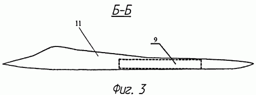
Claim
1. Fighter weapon control system, including multi-function on-board radar and optical-electronic, such as a television, a target system board set guidance equipment and on-board navigation equipment kit with sensor flight information, a set of indicators of the sighting, navigation and flight information, and computer-related system with the listed devices and on-board equipment including radio telemetry communication, including a transceiver device connected via the encoder input and output via radio decoder to a computer system and the other two inputs coupled to the transducer signals to digital form, the software device frequency hopping transceiver connected to access to the transceiver and the inputs to the two transducers signals to digital form and to a computer system, a control panel with two turn knob to set the modes of communication and radio telemetry rank fighter in the group interaction, the remote target distribution with the input button and cancel transmitted by radio telemetry communication and Key Pad these tasks, the light tactical situation to play the exchange of information and tasks, and the control panels are equipped with transducers and target distribution of their output signals to digital form, and the tactical situation indicator analogue converter and all three devices connected to the computer system, wherein further comprising air terminal automation system integrated communications, navigation and communication, connected to the input of the onboard software sets of equipment for receiving radio telemetry communication for local multiplex communication line terminal commands and outputs / inputs to a computer system to transmit / receive on the local lines multiplexed communication signal terminal interaction with their own avionics fighters.
2. Fighter armament control system of claim 1, characterized in that the air terminal automation system combined, connect its input / output to the total airborne backbone data bus, controlled by a computer system commands from the control information field single cabin avionics fighters.
 
KNAAPO site very slow after high-res T-50-4 pics posted.


Here's what I grabbed (resaved slightly lower quality to allow posting)
 

Attachments

  • t-50-4_05_hires-a.jpg
    t-50-4_05_hires-a.jpg
    1.4 MB · Views: 86
  • t-50-4_04_hires-a.jpg
    t-50-4_04_hires-a.jpg
    900.7 KB · Views: 86
  • t-50-4_03_hires-a.jpg
    t-50-4_03_hires-a.jpg
    1.4 MB · Views: 106
  • t-50-4_02_hires-a.jpg
    t-50-4_02_hires-a.jpg
    1.3 MB · Views: 105
  • t-50-4_01_hires-a.jpg
    t-50-4_01_hires-a.jpg
    1.1 MB · Views: 85
more
 

Attachments

  • t-50-4_11_hires-a.jpg
    t-50-4_11_hires-a.jpg
    1.3 MB · Views: 66
  • t-50-4_10_hires-a.jpg
    t-50-4_10_hires-a.jpg
    1.2 MB · Views: 91
  • t-50-4_09_hires-a.jpg
    t-50-4_09_hires-a.jpg
    1.1 MB · Views: 107
  • t-50-4_08_hires-a.jpg
    t-50-4_08_hires-a.jpg
    1.2 MB · Views: 74
  • t-50-4_07_hires-a.jpg
    t-50-4_07_hires-a.jpg
    1.2 MB · Views: 68
  • t-50-4_06_hires-a.jpg
    t-50-4_06_hires-a.jpg
    1.6 MB · Views: 49
more
 

Attachments

  • t-50-4_16_hires-a.jpg
    t-50-4_16_hires-a.jpg
    1.4 MB · Views: 48
  • t-50-4_15_hires-a.jpg
    t-50-4_15_hires-a.jpg
    485.6 KB · Views: 42
  • t-50-4_14_hires-a.jpg
    t-50-4_14_hires-a.jpg
    626.9 KB · Views: 37
  • t-50-4_13_hires-a.jpg
    t-50-4_13_hires-a.jpg
    751.9 KB · Views: 35
  • t-50-4_12_hires-a.jpg
    t-50-4_12_hires-a.jpg
    1.4 MB · Views: 37
last
 

Attachments

  • t-50-4_17_hires-a.jpg
    t-50-4_17_hires-a.jpg
    1.4 MB · Views: 55
  • t-50-4_18_hires-a.jpg
    t-50-4_18_hires-a.jpg
    1.4 MB · Views: 52
  • t-50-4_19_hires-a.jpg
    t-50-4_19_hires-a.jpg
    1.4 MB · Views: 49
  • t-50-4_20_hires-a.jpg
    t-50-4_20_hires-a.jpg
    1.4 MB · Views: 100
nope. this season they prefer 'em in dark aubergine (oh, God, please nooooo)
 
flateric said:
nope. this season they prefer 'em in dark aubergine (oh, God, please nooooo)
http://www.youtube.com/watch?v=umDr0mPuyQc

This will be my reaction atleast. :D Whoever that had the bright idea of aubergine color should be sent to Siberia. Seriously.
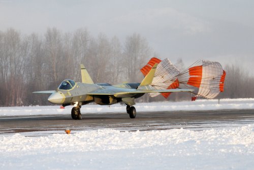
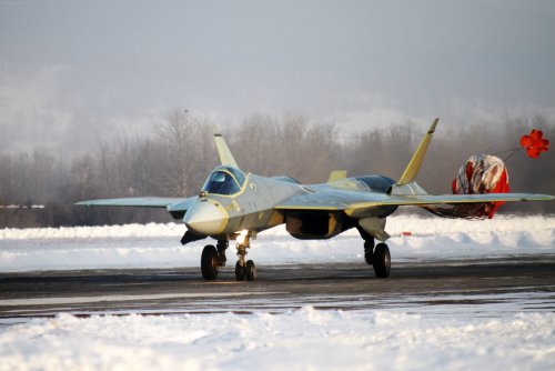
 

Please donate to support the forum.

Back
Top Bottom