Sukhoi Su-57 flight testing, development & operations [2012-current]

Radical said:
It appears that the T-50 shares a lot of features with the YF-23. Lets see if the T-50 can live up to the YF-23's incredible performance in speed.

1. The YF-23 was WAY cleaner than the T-50.
2. It helps when you have YF119s/YF120s in the back end.


Radical said:
Also, judging how wide the T-50 is, it looks like it can generate a whole lot of lift. Really wonder what the turn rate is. It might far exceed the F-22.

But can it out turn an AIM-9X. One would guess the answer is somewhere between "no" and "hell no". [/quote]
 
sferrin said:
Radical said:
It appears that the T-50 shares a lot of features with the YF-23. Lets see if the T-50 can live up to the YF-23's incredible performance in speed.

1. The YF-23 was WAY cleaner than the T-50.
2. It helps when you have YF119s/YF120s in the back end.

Clean isn't everything. Also, let's leave engines out of this, since I'm talking strictly about the merits of the T-50's aerodynamic shape. It has a similar layout to the YF-23 and that may be an indication that the T-50 conforms to the area rule very well. If we assume that the T-50 is using the hypothetical F119 equivalent that's being developed, it may meet or exceed the F-22's current speed performance. This is just my conjecture. Perhaps an aerospace engineer can provide more insight on this.

Radical said:
Also, judging how wide the T-50 is, it looks like it can generate a whole lot of lift. Really wonder what the turn rate is. It might far exceed the F-22.

But can it out turn an AIM-9X. One would guess the answer is somewhere between "no" and "hell no".

I'm trying to talk about aerodynamic performance of the aircraft shape, not missiles. The Russians also have high off-boresight missiles. In any case, I'm just postulating that the wide fuselage of the T-50 seems to indicate that it generates lots of lift and it may exceed the F-22 in turning performance.
 
saintkatanalegacy said:
chuck4 said:
The more important question is "is it accurate?"


I thought the weapon bays had 4 hard points each.

2 missiles per main bay.

of course, some will argue they could have easily fitted 3. but requirements are requirements

Well, the new generation of folding fin <700 kgw weapons (ultra long range AAMs, guided bombs, antiship missiles etc...) all seem to mysteriously be the same size as each other and perfectly match the dimensions of each of the four bay doors...

What are the exact requirements? I missed this being published! I personally like Paralay's layout (central 700kg mount, with 350kg mounts on either side - would allow modification to cary a 1500kg munition internally as well).
 
sferrin said:
1. The YF-23 was WAY cleaner than the T-50.
How so? It got rid of two tail surfaces but that's about it, in many other ways there is indeed a resemblance between the two. Moreover, although this is an inaccurate indicator, the T-50 probably has a smaller frontal area thanks to its straight inlet ducts and reduced vertical tail size.

sferrin said:
But can it out turn an AIM-9X. One would guess the answer is somewhere between "no" and "hell no".
It doesn't need to - it will likely be fitted with DIRCM from the start.
 
Couldn't f-22's huge flat bottom also act as an enormous lifting surface at high AOA to help it turn just like the wide fuselage of the t-50?


Seems to me f-22's elevators, being further behing the engines and center of gravity and lift, would also have greater pitch authority.


Also, one of the advantages of f-22 is not that it's absolute maximum sustained turn rate was higher than anything else. Instead it could sustain a high turn rate over a greater range of altitudes and airspeeds. So can the T-50 match f-22's turn rate at speeds and altitudes where f-22 would most prefer?
 
Trident said:
sferrin said:
1. The YF-23 was WAY cleaner than the T-50.
How so? It got rid of two tail surfaces but that's about it, in many other ways there is indeed a resemblance between the two. Moreover, although this is an inaccurate indicator, the T-50 probably has a smaller frontal area thanks to its straight inlet ducts and reduced vertical tail size.

Aside from angled vertical tails and two engines there is little resemblance between the two.


Trident said:
sferrin said:
But can it out turn an AIM-9X. One would guess the answer is somewhere between "no" and "hell no".
It doesn't need to - it will likely be fitted with DIRCM from the start.

ROFL!!! "We don't need to manuever. That's what this big wing is for." What?
 
sferrin said:
Aside from angled vertical tails and two engines there is little resemblance between the two.

Context. In terms of being aerodynamically clean (which is the subject we were talking about), the differences aren't particularly big and they could go either way. In detail the resemblance is pretty moderate, but then many people insist that the F-14 is the closest Western counterpart of the Flanker in configuration, when actually (aside from twin widely spaced engines and tails) the F-16 is much closer.

Trident said:
ROFL!!! "We don't need to manuever. That's what this big wing is for." What?


There are obviously uses for agility and high lift other than out-turning AIM-9X missiles. Suffice it to say that both the big wing and DIRCM are there - what exactly motivated these design choices is a question only Sukhoi can answer in detail.
 
Trident said:
sferrin said:
Aside from angled vertical tails and two engines there is little resemblance between the two.

Context. In terms of being aerodynamically clean (which is the subject we were talking about), the differences aren't particularly big and they could go either way.

They're huge. There are a lot more areas for potential interference drag on the T-50. There is a lot less blending between shapes on the T-50 with many abrupt changes of surface direction. The YF-23 is pretty slick in the latter sense (yes I know that's not all there is to it), and it's smaller to boot. It's wet area is much smaller than the T-50.


Trident said:
In detail the resemblance is pretty moderate, but then many people insist that the F-14 is the closest Western counterpart of the Flanker in configuration, when actually (aside from twin widely spaced engines and tails) the F-16 is much closer.

Reading this one can't help but wonder if we're speaking of the same aircraft.

Trident said:
Trident said:
ROFL!!! "We don't need to manuever. That's what this big wing is for." What?


There are obviously uses for agility and high lift other than out-turning AIM-9X missiles. Suffice it to say that both the big wing and DIRCM are there - what exactly motivated these design choices is a question only Sukhoi can answer in detail.

I've not seen any evidence whatsoever of a DIRCM turret on the T-50. Could you point it out?


(and why the hell do the undeletable "" keep sticking themselves at the end of my posts?)
 
sferrin said:
The YF-23 is pretty slick in the latter sense (yes I know that's not all there is to it), and it's smaller to boot. It's wet area is much smaller than the T-50.

Huh? The YF-23 was probably larger, certainly in length and most likely also in volume, having to contain inside a smoothly-faired outline longer inlet ducts with much greater vertical and horizontal displacement between intake location and engine compressor face. While the T-50 may have more complex shaping underneath, its topside is arguably cleaner.

sferrin said:
I've not seen any evidence whatsoever of a DIRCM turret on the T-50. Could you point it out?

It's the hemispherical fairing behind the canopy that was originally thought to be a second IRST. Information on the integrated 101KS EO system of the T-50 revealed a few months ago called it a "laser-based optical countermeasures station" or some such clunky literal translation of its native Russian designation. I don't know about you, but that screams DIRCM to me :)

sferrin said:
(and why the hell do the undeletable "quote" keep sticking themselves at the end of my posts?)

Yeah, you have to be pretty cunning to get rid of that and I'm not entirely sure how I manage to do it. Rearranging stuff by cutting and pasting seems to help sometimes, as does not trying to mark it for deletion with the mouse but placing the cursor somewhere in the vicinity and then moving it with the arrow keys as necessary. Also, I'm having other issues with formatting posts, breaks and paragraphs are a complete mess on my end. What browser are you on? Opera here.

EDIT: hm, breaks seem to work alright when modifying your post after the fact. Weird.
 
Guy's, you're going to have a long argument unless you distinguish:
- turn rate vs. speed (turn circle)
- subsonic vs. super-sonic maneuverability
- sustained maneuverability vs. initial maneuverability
- uncontrolled supermaneuverability (e.g. Cobra) and controlled supermaneuverability (where moment remains manageable and attitude is smoothly controlled through all angles of attack)

From a tactical sense you have to distinguish between attempting to turn inside a missile (aircraft have larger surface areas) and attempting to produce heading changes that force a BVR missile to waste energy by making frequent course corrections.
 
Trident said:
Information on the integrated 101KS EO system of the T-50 revealed a few months ago called it a "laser-based optical countermeasures station" or some such clunky literal translation of its native Russian designation. I don't know about you, but that screams DIRCM to me :)
O in designation 101KS-O stays for Oborona (Defense) and its defense function is officially confirmed in UOMZ lefalet
But - there are some hints that this magic ball do carry *both* functions of IRST _and_ DIRCM
 
In the YF-23 vs T-50 debate, you have to consider frontal area and surface area are more of a concern for subsonic performance, not supersonic. For supersonic performance, you're better off looking at the wave drag (Area distribution) and the fineness ratio. Just saying...
 
Guys, it seems to me DIRCM could only work against older infra-red missiles that uses a spinning slotted disc homing system. A pulsing ir source on the target really wouldn't work very well in principle against a imaging IR seeker.


Thoughts?
 
chuck4 said:
Guys, it seems to me DIRCM could only work against older infra-red missiles that uses a spinning slotted disc homing system. A pulsing ir source on the target really wouldn't work very well in principle against a imaging IR seeker.


Thoughts?
Pulsed IR sources aren't really what is referred to as DIRCM today, they are an obsolete technology that is more commonly called 'IR jammer'. Russia has been fielding this technology for a very long time (check out any military Mi-8 or Mi-24 - chances are it will have an IR jammer, not unlike the analogous 'Disco Ball' on various US helos), so it stretches plausibility somewhat to assume that they would fit a 30 year old technology that isn't even effective any more to their latest fighter design. Chances are extremely high that it is a laser-based system which can overpower even imaging seekers by saturating the detector array, similar to various Western (and at least one other Russian) devices, including the one planned for the F-35.
 
flateric said:
Trident said:
Information on the integrated 101KS EO system of the T-50 revealed a few months ago called it a "laser-based optical countermeasures station" or some such clunky literal translation of its native Russian designation. I don't know about you, but that screams DIRCM to me :)
O in designation 101KS-O stays for Oborona (Defense) and its defense function is officially confirmed in UOMZ lefalet
But - there are some hints that this magic ball do carry *both* functions of IRST _and_ DIRCM
I'm not perfectly certain how other DIRCM systems do fine tracking of their targets after coarse acquisition by the MAWS, but perhaps this is a closed-loop system which uses the same optics as the laser beam to keep itself pointed at the missile for greater accuracy?
 
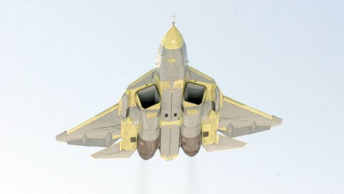
I wanted to do a bit of analysis on the design itself. According to Dr. Raymer's aircraft design book, Amax (the cross-sectional area of the aircraft which is largest) has a large contribution to wave drag and reducing this value can result in a less draggy aircraft than simply smoothing out the volume distribution would. For that reason, I decided to try to estimate what Amax might be for the T-50.

Very often it seems that the wing contributes largely to the volume of an aircraft and is therefore where Amax is most likely to be. I figured there were two likely places to start on the wing to determine the location of Amax: the point where the root chord is thickest, and the point where the wingspan is at a maximum. I initially thought that Amax would be somewhere between these two points, but for the T-50 at least, my calculations suggested that it was right at the leading edge of the wingtip. If this is true, then that means that Amax for the T-50 is located about 71% down the length of the aircraft (assuming length is 0% at the tip of the nose and 100% at the tip of the tail sting). This is quite a bit further down than the 50% suggested for the ideal Sears-Haack body shape, but this is expected since the T-50 is likely optimized for speeds a good bit above Mach 1. This high speed efficiency would require the rearward bias of Amax that we see.

I used Matej's 5-view of the T-50 in order to attempt to reconstruct the cross-section at the predicted point of Amax, but I'm not sure how well I did (some critical features were hard to see. It's not his fault; it's just a limitation of 5-views in general). One critical piece of information I was missing was the percent thickness of the wings. For this reason, I made 3 different estimations assuming different degrees of thickness. In one, I assumed the wings were 4% thick (the same as the F-16). For the second, 6% (similar to the F-22). Finally, 8% (a very high thickness for a fighter). Initially, I didn't think thickness would affect Amax very much. It seemed to me that the differences were significant, however.

If the wingspan of the T-50 is 14 meters (another uncertainty; for me at least), I end up with the following calculations for Amax.

4% thick = 8.2 square meters
6% thick = 9.6 square meters
8% thick = 10.9 square meters

The reason I didn't go past the tenths place was due to uncertainty; working with pixels leaves a lot to be desired. For this reason, along with some of the difficulties involved in the determining the geometry of the aircraft, I would only consider these ballpark figures. To be perfectly honest, I don't know what a "normal" value for Amax would likely be. Can anyone else shed light on whether these numbers sound reasonable or not? I might end up doing a similar analysis for the F-22A in order to do a comparison. Perhaps the YF-23 as well.

Criticisms of my technique and suggestions for improvement are welcome. By the way, I did remember to subtract the capture area of the inlets when making these estimates.

EDIT: I just used Paralay's detailed T-50 schematics to do another measurement. This time Amax came out around 5.13 square meters. That's a very large margin of error compared to my initial estimates. However, he conveniently had a cross-section drawn of the part I needed, and it looked better than my own drawing. I'd trust this second measurement over the first bunch (it's also closer to the given Amax for Dr. Raymer's Lightweight Supercruise Fighter concept in the back of his book, which he lists at 1.586 square meters. Keep in mind that his LWSF is significantly smaller than the T-50). The airfoil thickness in his drawing appears to be around 4.6% thick, which is not unreasonable. Just to be thorough, however, I'll do a quick estimate of other airfoil thicknesses (I found it interesting how Amax varied almost linearly with thickness for my initial estimates. That probably wouldn't hold true for exceedingly thick or exceedingly thin airfoils, but it should be a good guideline for simple extrapolation):

If Amax = 5.13 square meters for 4.6% thickness, then:

4% thickness ~ 4.9 square meters
6% thickness ~ 5.7 square meters
8% thickness ~ 6.5 square meters
 

Attachments

  • T50wing.jpg
    T50wing.jpg
    12.9 KB · Views: 1,098
Is your calculation part of more calculations? Or another question: what is the benefit of having calculated Amax?
 
Reaper said:
Is your calculation part of more calculations? Or another question: what is the benefit of having calculated Amax?


No other calculations at this point. Trying to get an idea of how draggy it is compared to other aircraft (which, of course, requires Amax figures from other designs to compare it to). I know that's not the only factor that affects drag, but it should at least help bring us one step closer to understanding it. At least, I figured it would be better than simply saying "probably this" and "probably that" and instead actually put some numbers to it. I wanted to do a volume distribution plot for the plane as well, but that takes considerably more time. I may yet get to that, however.

The F-23A diagram posted in another thread on here is very clear and it shouldn't take me too much effort to figure Amax for it as well. I'll try to get around to that soon.

EDIT: I calculated the F-23A's Amax at 6.9 square meters. That's higher than my newest figures for the T-50, but that doesn't necessarily mean the T-50 truly has the lower maximum cross-sectional area. For one, there are uncertainties in the T-50's true cross-sectional shape when using civilian-made diagrams. Measuring the pixels also lowers the certainty. The T-50's true Amax could lie somewhere between my old and new measurements (could be anywhere from 4.9 to 10.9 square meters). My guess is that Amax values between the T-50 and the F-23A are in the same "ballpark". Measuring the YF-23 might be preferable, as I believe it was even better area-ruled than it's proposed production version (the ruling was relaxed for better weapon carriage or something like that for the F-23A). Comparing prototype to prototype would therefore be the better choice.
 
Patents Patent :)

Intake: http://www.findpatent.ru/patent/246/2460892.html
Antenna: http://www.findpatent.ru/patent/245/2453955.html
Structure: http://www.sumobrain.com/patents/wipo/Airframe-highly-maneuvrable-multi-mode/WO2012102640A2.html
 
Quick! - send some of those back in time so we don't have to debate about the inlet shape ;)
(or the whether it has a Su-27's internal structure for that matter)
 
Unfortunately, the external structure of PAK-FA in the early days was misleading in terms of the position of the damn compressor face. Can't tell how high or low it is. Well, at least my model there was "close" enough compared to the drawing ;D
 
Kryptid said:
Reaper said:
Is your calculation part of more calculations? Or another question: what is the benefit of having calculated Amax?


No other calculations at this point. Trying to get an idea of how draggy it is compared to other aircraft (which, of course, requires Amax figures from other designs to compare it to). I know that's not the only factor that affects drag, but it should at least help bring us one step closer to understanding it. At least, I figured it would be better than simply saying "probably this" and "probably that" and instead actually put some numbers to it. I wanted to do a volume distribution plot for the plane as well, but that takes considerably more time. I may yet get to that, however.

The F-23A diagram posted in another thread on here is very clear and it shouldn't take me too much effort to figure Amax for it as well. I'll try to get around to that soon.

EDIT: I calculated the F-23A's Amax at 6.9 square meters. That's higher than my newest figures for the T-50, but that doesn't necessarily mean the T-50 truly has the lower maximum cross-sectional area. For one, there are uncertainties in the T-50's true cross-sectional shape when using civilian-made diagrams. Measuring the pixels also lowers the certainty. The T-50's true Amax could lie somewhere between my old and new measurements (could be anywhere from 4.9 to 10.9 square meters). My guess is that Amax values between the T-50 and the F-23A are in the same "ballpark". Measuring the YF-23 might be preferable, as I believe it was even better area-ruled than it's proposed production version (the ruling was relaxed for better weapon carriage or something like that for the F-23A). Comparing prototype to prototype would therefore be the better choice.

I think the cross sections of the YF-23 is also available on Scott Lowther's website. The F-23A has higher fineness ratio that the YF-23, although its contour might not be as area-ruled.
 
Hello!


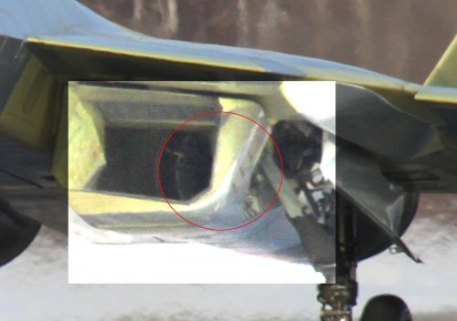
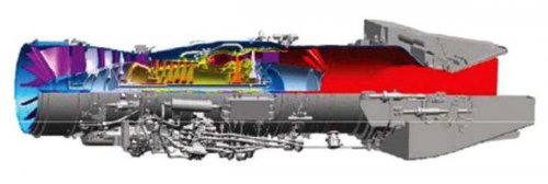
If we can see the forward section of the Saturn 117 engine...

Which is the length of this engine??

best wishes!
 

Attachments

  • t-50-3_23_hires_2.jpg
    t-50-3_23_hires_2.jpg
    108 KB · Views: 807
  • t-50-3_23_hires_3.jpg
    t-50-3_23_hires_3.jpg
    150.8 KB · Views: 597
Sometime back the Japanese release cgi of an stealth engine they are working on for the Shinshen. It shows a set of large, very deeply curved stators located in front of the fan rotor face, but still inside the fan casing. The stator supposedly shields the fan from the radar. Maybe the Russians plan to use the same strategy.
 
As someone once said to me somewhere when I was taking a gander up the inlet duct, "that's not the engine". Could be the same here.
 
there will be radar blocker, but at least at current stage it looks quite different from solution proposed for ATD-X
(and, actually, final configuration is not chosen yet)
T50-3 doesn't have the 'thing', so Photoshop filters wont't help anyway
 
chuck4 said:
Sometime back the Japanese release cgi of an stealth engine they are working on for the Shinshen. It shows a set of large, very deeply curved stators located in front of the fan rotor face, but still inside the fan casing. The stator supposedly shields the fan from the radar. Maybe the Russians plan to use the same strategy.

Hi!

An idea of Paralay:

http://paralay.com/pakfa/t50%20(21).jpg

;)
 

Attachments

  • t50 (21).jpg
    t50 (21).jpg
    423.1 KB · Views: 575
LowObservable said:
As someone once said to me somewhere when I was taking a gander up the inlet duct, "that's not the engine". Could be the same here.
Was it a "deee-vice"? ;)
 
some say it's a device. some say it's a blocker. some say it's the fan blade material that's gonna be made of RAM*
 
saintkatanalegacy said:
some say it's a device. some say it's a blocker. some say it's the fan blade material that's gonna be made of RAM*

How credible is a high stress, moving part being made of RAM?

How good is (any) RAM material in hiding itself when it is unsupported by geometry, and being stared at directly by a radar?
 
Wil said:
more here:

these and much more here
http://www.knaapo.com/rus/gallery/events/combat/t-50/t-50-1.wbp
http://www.knaapo.com/rus/gallery/events/combat/t-50/t-50-2.wbp
http://www.knaapo.com/rus/gallery/events/combat/t-50/t-50-3.wbp
 
chuck4 said:
How credible is a high stress, moving part being made of RAM?

How good is (any) RAM material in hiding itself when it is unsupported by geometry, and being stared at directly by a radar?

a. coat the fan blade
b. composite ceramic ram(?)
c. go pseudo-Japanese style(future turbines)
d. all of the above(???)
e. none of the above(device, blocker, OMG fan blade! not stealth aircraft)
 

Please donate to support the forum.

Back
Top Bottom