Su-57 intakes, supercruise performance and 2nd stage engine

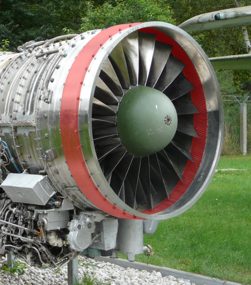
No matter which engine it is, what got my attention was the raised land on the fan case aft of the inlet variable vane synchronizing ring. That looks just like the TF30-P-414 first blade containment ring:
1. Does this fan have a 1st stage blade liberation problem that requires containment?
2. The containment is likely to be made of steel to prevent any Ti blade to Ti case rub induced rapid oxidation events (i.e. Fire !!). There goes part of your 10:1+ thrust to weight ratio.

Annular volume for fan rotor casing treatment? This is a *very* popular feature in Russian engines, after all (IIRC it's actually a Russian invention) - to the extent that I'd be surprised if this engine did NOT have it.

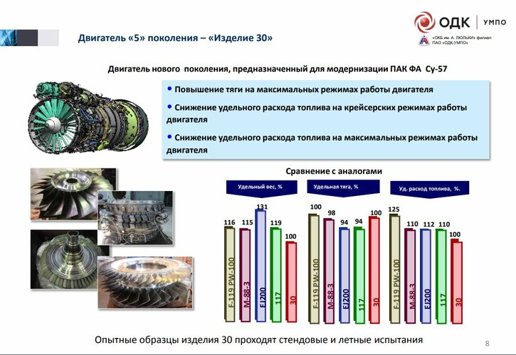
EDIT: As far as blade liberation risk, if (as claimed) this engine draws heavily on the Izd.30, the new fan would be a wide chord blisk (the wide chord blades are actually mentioned explicitly on the slide posted earlier). You'd have to seriously mess up to get a design especially prone to throwing blades out of that, certainly the slide also touts improved FOD resistance.
 
Last edited:
the new fan would be a wide chord blisk (the wide chord blades are actually mentioned explicitly on the slide posted earlier). You'd have to seriously mess up to get a design especially prone to throwing blades out of that, certainly the slide also touts improved FOD resistance.
Blade off isn't the only failure mechanism we need to worry about with fans or blisks. You need to be ready to contain the entire blisk, or significant portions of one, cf AF066 losing its entire fan and inlet over Greenland https://en.wikipedia.org/wiki/Air_France_Flight_066

(A slightly less challenging environment, but I just had the injection-moulded cooling fan in my central heating boiler reduce itself to plastic shards lying in the bottom of its casing - so that kind of failure is fresh to mind).
 
Last edited:
I don't think even civilian regulations (which don't apply here anyway) require a liberated disc to be contained. In fact, the weight of a containment able to handle *that* would probably more than negate any savings from having a blisk in the first place and you'd simply stick with a conventional disc and blades. A lose blisk is going to be one of those failures you have to accommodate by designing to ensure a probability below 10^-9. Which, to be fair, will be more readily done than with a conventional configuration.
 
Last edited:
Annular volume for fan rotor casing treatment? This is a *very* popular feature in Russian engines, after all (IIRC it's actually a Russian invention) - to the extent that I'd be surprised if this engine did NOT have it.

EDIT: As far as blade liberation risk, if (as claimed) this engine draws heavily on the Izd.30, the new fan would be a wide chord blisk (the wide chord blades are actually mentioned explicitly on the slide posted earlier). You'd have to seriously mess up to get a design especially prone to throwing blades out of that, certainly the slide also touts improved FOD resistance.
I’ve seen various casing treatments. So far, I haven’t seen any that need a large external volume (acoustic?) like is seen in the photo. Doesn’t mean that the Russians don’t have something different.
 
There are a wide variety, quite a few of which have a sizeable circumferential plenum. But even those without a backing volume (e.g. EJ200 type circumferential grooves) are going to require a thickness increase where the treatment is if the casing is otherwise very thin-walled. Note how there is no isogrid machining in the area concerned on the EJ200, for example.

Here's a very typical Russian implementation (R29-300) combining a thin machined casing and a large backing volume:
1731155886408.png
 
Last edited:
I would be interested if anyone has more information on these Russian casing treatments, and why the large external volume. Is there some sort of internal acoustic cavity inside that ring volume?

Compared to circumferential groovies that are part of the blade tip abradable surface (using engine tip to case contact during engine run-in to set minimum tip clearance) that I have seen on some newer western engines, the R29-300 shown only extends over the front half of the blade tip.
 
If in December Su-57 bunch we will see Al-41F1 — you’ll have to ask this question again in 2025…
 
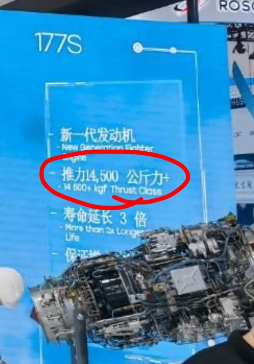
It looks like the engine index is "177S". The result is a 3x longer service life (6000) and probably lower consumption. Thrust remains in the 14,500 kgf class.
 
Declared thrust with afterburning +30%, which is 16250 kgf
In that case, 177S isn't a "Hybrid"?
Isn't index "177S" only a typo?
 

Attachments

  • Screenshot_2024-11-10-15-49-21-08_40deb401b9ffe8e1df2f1cc5ba480b12.jpg
    Screenshot_2024-11-10-15-49-21-08_40deb401b9ffe8e1df2f1cc5ba480b12.jpg
    600 KB · Views: 65
Last edited:
Is there news or timeline on the 2D nozzle with thrust reverser? Is it a reasonable assumption that it will be part of the Megapolis upgrade with the Izd 30 engine?
 
So they went with same thrust as 117 but increased fuel efficiency. Wonder if they make a variant with same fuel efficiency as 117 but more thrust.
 
A little more clarity has emerged: izd.177S(presented in Zhuhai) is a replacement for izd.117S for the Su-35SE, izd.177(not presented) is a replacement for izd.117 for the Su-57E.
So new fan gives +3.5% thrust, meaning that 177 will have 15t AFB non-emergency mode.
Fuel efficiency doens't match. Slide say 0.77 at mil thrust. OG Al-31 had 0.75, it's not an improvement.
Edit. some data suggest fuel efficiency of AL-31 as 0.795 at mil thrust. OTOH 117S has the same 0.77, which doesn't match with what they saying about it's increase.
 
Last edited:
Those photos confirm the new LPC is a wide-chord blisk and the presence of casing treatment.
 
And with a high probability, a variant for single-engine use in the T-75 program is being considered.
 
In any case, the published data introduced doubts and conjectures not only about the Izd. 177S, but also the published information about 117 and, after all, Izd. 30.
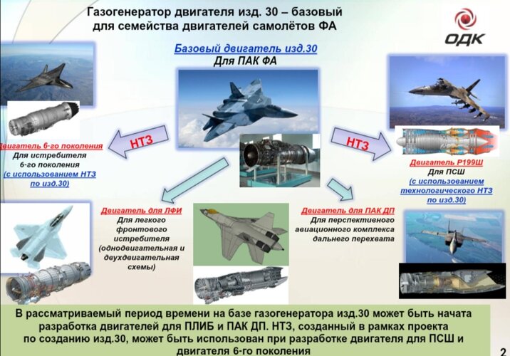
30.jpg Btw, for years there was an unfounded belief that the thrust of the 30 would be at the level of 170-180 kN. Realistically it will be slightly over 150 kN.
 
Btw, for years there was an unfounded belief that the thrust of the 30 would be at the level of 170-180 kN. Realistically it will be slightly over 150 kN.
That's very much depends on weight of izd.30. As "удельный вес", сompared to 117 is 19% better. So up to 19% thrust increase compared to 117. Or even more, if izd.30 is heavier.
 
Last edited:
Most statements about the izdeliye 30, or AL-51F-1, came from journalists, some credible and some aren't. Lyulka-Saturn and UMPO themselves have been relatively quiet about the details, save for some passing statements, and the 2021 UMPO slide deck offers some quantitative information. Reputable sources generally state that the izdeliye 30 is "17-18% more effective" than the izdeliye 117, which indicates 16-17 metric tons of thrust. 18 metric tons is often thrown around, but that may be a number achieved in certain red-lined bench test conditions rather than the rated number.

The izdeliye 117 weighs about 1,600 kg, about the same as the 117S and the main difference between the two engines is the control system. The izdeliye 30 is generally considered to be a bit lighter.
 
It has nothing to do with izd.30. The pic is for S-75, which was never claimed to have izd.30. All official said that it will get an new engine with thrust in 16t class. And we've seen UMPO presentations about new common engine, which is 177S. So it's likely that variant, but more powerful.
Also note 4000h engine life, when ODK guys always mention 6k hour engine life for their new engines
 
Last edited:
The picture is not about the "S-75" and no one has ruled out the use of the Izd. 30. The figure of 16,500 kgf can theoretically refer to the Izd. 177 variant, but let's ask ourselves: does the gas generator from the original Izd. 99 have the potential to increase thrust to such a level?
 
As a reminder
 

Attachments

  • Screenshot_20241114_135156.jpg
    Screenshot_20241114_135156.jpg
    251.1 KB · Views: 55
but let's ask ourselves: does the gas generator from the original Izd. 99 have the potential to increase thrust to such a level?
The presentation mentions both 99 and 117 as source of gas generator and AFB.
We don't know diameter of 177S - is it 905 or 924mm (max limit for Su027 family)? Does it use GG from izd.99 or 117?
If it has 14.5 ton with GG from 99, then replacing it with GG from 117 might do the trick.
Also, chinese infocrad shows it as 14500+ thrust class, so it has room for more.
View: https://imgur.com/wpV6uvh
 
Last edited:
One can agree with that. Regardless of the fact that a variant may arise that may not reflect the construction limits of the T-10 platform at all.
 
The second stage is necessary at least because the tactical requirements of the task are not fulfilled. It has already been decided to produce 117 in series. The PAK FA of the first stage will go into series from the 4th quarter of 2017, the second stage - only from 2024.At ed. 30, 15% superiority in bench traction and 10% lower consumption is expected. At the same time, radically better altitude and speed characteristics are expected: up to 45% superiority in thrust at altitude and max compared to 117. It is also expected that the RCS will decrease by 4 times on the compressor side and three times on the turbine side, and the IR signature will decrease by two times compared to the indicators of ed. 117.
2015
 
Concerning fuel consumption, SFC is a rather static figure and not the complete picture. If SFC is the same for two engines at military power for example, but one engine produces 20% thrust for example, the same airframe powered by it may obtain a particular cruise speed/altitude at a lower throttle setting which entails a lower fuel consumption as well.
 
Concerning fuel consumption, SFC is a rather static figure and not the complete picture. If SFC is the same for two engines at military power for example, but one engine produces 20% thrust for example, the same airframe powered by it may obtain a particular cruise speed/altitude at a lower throttle setting which entails a lower fuel consumption as well.
It depends on the SFC of each engine at the required power setting for that flight condition. Engines typically have their best SFC at around 80-90% of Mil power, and it gets worse above and below that SFC bucket. The higher thrust engine may be operating below that optimum power setting.

On the other hand, the higher thrust engine, operated at its optimum cruise SFC may allow the cruise to at a higher altitude, which lowers available thrust and fuel flow, resulting in lower actual fuel burn. There are a lot of variables in the equation…..
 

Similar threads

Please donate to support the forum.

Back
Top Bottom