Su-57 intakes, supercruise performance and 2nd stage engine

The change was directed in 2006 by the head of the Russian Air Force at the time, Viktor Mikhaylov. I would consider that to be rather official.
Seems a legit source, even when it is still unspecific about the nature of the "set speed" they refer to. Nevertheless, the statement in its full context has not aged very well, judge for yourself:

V. Mikhailov said that the fifth-generation aircraft of front-line aviation will make its first flight no later than 2007. According to him, all work on this aircraft is strictly on schedule, its airframe has been developed, its characteristics have been determined and approved.

Mikhailov also said that he instructed the developers of the car to reduce the set speed from 2.15 M to 2M, in order to ensure a gain in other characteristics due to this.

According to him, in parallel with the development of this aircraft, its lightweight modification will be designed with the same avionics and the same engine, but with less powerful weapons.


The last paragraph in particular is interesting, either they announced LTS back in 2006 (and from the VKS no less), or they just talk about a plan that went nowhere. By what UAC says, LTS was only started very recently.

Has it changed then? Who knows, as there haven’t been any announcements to the contrary. It would be of rather limited tactical value.
You can find more information about Russian military plans, the more into the past you go. As of recently, they publish basically nothing technical. In any case we know there have been reviews of the design goals throughout the whole program, like with the decision to go for the second stage engine.

The tactical value again is your personal assessment and does not consider the stated role of the plane as an interceptor.

Even the Su-30SM and MiG-35 with variable inlet ramps have a maximum speed of Mach 2
Even less, but they are just versions of 2+ M planes and so it would make sense to use an already developed solution rather than to develop and test the new intake solution from scratch. Besides the data we have are always for export versions, remember that. But Su-57 is not a version of a previous design, and having more powerful engines, even with an inferior pressure recovery, it should be able to reach 2 M with fixed intakes as the F-22 or F-16 does. With the Su-35's example you are not even talking about a <2 M plane. So I don't think you have managed to explain why to equip the Su-57 with variable intakes if its max speed is 2 M.
 
You are just replaying an old Keymags debate about the top speed of the Su-57. Supercruise is long since forgotten in this topic.
Starting from a premise (Su-57 top speed is faster than Mach 2 because I believe it is) you are trying to prove the premise true.
 
Last edited:
The most likely explanation for the adoption of the variable inlet was some combination of lack of confidence in alternative fixed inlet designs looked at and/or lack of confidence in the engines to help the aircraft hit the required performance (with variable inlet likely seen as a way to some what compensate for that potential shortfall).
Now as discussed above it may be the case that some of performance requirements have been relaxed or changed since that decision was made to go with variable inlets but they are clearly highly integrated into the design and offer better performance than if the decision was made to just fix them or replace with non-optimised alternate fixed inlet design “grafted on” to an otherwise unaltered airframe.
Otherwise this appears to be an exercise in zealotry - a true believer in their zeal seeing anything everything as evidence that their zealousness is correct and well earned. The Su-57 just HAS to be better than rival X, Y or Z so highly circumstantial (and potentially irrelevant and/ or wrong) “facts” A, B and C prove it, and if under any reasonable examination they don’t actually do so then theirs always lots more letters in the alphabet and arguments (of varying validity) to make.
 

I wouldn’t go with this argument. Variable geometry inlets have little benefit at supercruise speeds of ~Mach 1.5, so their ability to compensate for engine performance would be rather poor. Given the original PAK FA requirement for maximum dash of Mach 2.35, which was the same as the Su-27, and given the general mechanical similarity between it and the Su-57 in certain systems, this may be one aspect that was carried over. Reports have indicated that the max speed change was not done for aerodynamic reasons, and since it occurred in 2006 and well after the shape was frozen in 2004, keeping the inlet design the same would reduce the amount of engineering rework.

The tactical value again is your personal assessment and does not consider the stated role of the plane as an interceptor.
The VKS has a separate PAK DP program for a replacement interceptor. Whether that program will come into fruition is another matter, and in any case, fighters such as the Su-30 have been pressed into the interceptor role despite lack of supersonic persistence.

Starting from a premise (Su-57 top speed is faster than Mach 2 because I believe it is) you are trying to prove the premise true.
Circulus in probando much?
 
Last edited:
The most likely explanation for the adoption of the variable inlet was some combination of lack of confidence in alternative fixed inlet designs looked at and/or lack of confidence in the engines to help the aircraft hit the required performance (with variable inlet likely seen as a way to some what compensate for that potential shortfall).
Now as discussed above it may be the case that some of performance requirements have been relaxed or changed since that decision was made to go with variable inlets but they are clearly highly integrated into the design and offer better performance than if the decision was made to just fix them or replace with non-optimised alternate fixed inlet design “grafted on” to an otherwise unaltered airframe.
The suboptimal solution was used in a new plane out of lack of planing, time and rubles as usually. Totally unexpected explanation coming from you...

Otherwise this appears to be an exercise in zealotry - a true believer in their zeal seeing anything everything as evidence that their zealousness is correct and well earned. The Su-57 just HAS to be better than rival X, Y or Z so highly circumstantial (and potentially irrelevant and/ or wrong) “facts” A, B and C prove it, and if under any reasonable examination they don’t actually do so then theirs always lots more letters in the alphabet and arguments (of varying validity) to make.
I am not here to prove anything, much less in the "AIAA paper submittal" format some rather disingenuously appear to expect from classified programs, and I have not been proven anything in the contrary, either. I am discussing qualitative elements of the design and it just happens that some don't like to have said elements stated to them. As to your sustained lack of respect and poorly disguised insults, they say more about yourself than about me. You just stay classy and true to your line of zero contributions, 100% gossip.

The VKS has a separate PAK DP program for a replacement interceptor. Whether that program will come into fruition is another matter, and in any case, fighters such as the Su-30 have been pressed into the interceptor role despite lack of supersonic persistence.
Designers have stated the features of an interceptor been included in the design.

Circulus in probando much?
I am not trying to prove anything, I have said it too many times already. BTW I was left waiting for your proof about the reasons for the layout of the F-35, which you just stated, insisted in and called the discussion, much in the same way you complain above. In this thread though, you went for the easier role of taking cheap shots at certain arguments that you perfectly know cannot be proven and ignored the 80% of the argumentation composed of proven or reliable facts I provided. You did not prove to me your methodological rigour, your technical impartiality nor your ability to navigate complexity. To you everything is too complex and unintelligible, so better not to be talked about at all. Don't participate in the talk, then, nobody forces you.

The adjustable air intake ensures the best engine operating conditions in the entire range of heights and speeds. The disadvantage is that it is heavier. The non-adjustable air intake is designed for only one single flight mode. For example, the F-16 has subsonic maneuvering, the F-22 cruises at a speed of M = 1.5 All other modes are not calculated and are provided only by the stability of the engine
Yes, but the advantage of the variable intake is minimal below 2 M. The fixed design is stretched as it has to accomodate to a bigger spread of airflow velocities, it cannot simultaneously work properly in subsonic and high supersonic flight regimes. The patent talks explicitly about a variable intake optimized for Mn between 2 and 3, so it is either a design error or leftover from another design, or it addresses actual flight requirements.

You are just replaying an old Keymags debate about the top speed of the Su-57. Supercruise is long since forgotten in this topic.
Starting from a premise (Su-57 top speed is faster than Mach 2 because I believe it is) you are trying to prove the premise true.
I see the current discussion perfectly fitting in a propulsion/intakes thread for the Su-57 and with far less off-topic than many other discussions in the board, but at the end of the day the call is yours. The judgement you make misrepresents my line of reasoning and my intention, yes I do think it flies faster than 2 M for the data and hints I have collected, but I know this is not a proven fact and I am not very concerned about what other people think, specially what naysayers think, which is always predictable BTW. In any case I hope that I am entitled to make my point and present the evidence I see, as much as answer back when I receive rebuttals.
 
Last edited:
Designers have stated the features of an interceptor been included in the design.
Okay, and that doesn't indicate much; the Su-27P was also a long-range interceptor used by the V-PVO, serving alongside the MiG-31. Not indicative of anything one way or another, other than the Su-57 having very long range and endurance.

BTW I was left waiting for your proof about the reasons for the layout of the F-35, which you just stated, insisted in and called the discussion, much in the same way you complain above. In this thread though, you went for the easier role of taking cheap shots at certain arguments that you perfectly know cannot be proven and ignored the 80% of the argumentation composed of proven or reliable facts I provided. You did not prove to me your methodological rigour, your technical impartiality nor your ability to navigate complexity. To you everything is too complex and unintelligible, so better not to be talked about at all. Don't participate in the talk, then, nobody forces you.
What are you even talking about? I simply stated that the "stubbiness" of the F-35 has to do with a combination of factors (i.e. spot factor, component positioning), not just STOVL causing it in a linear manner, and provided examples of other configurations to demonstrate. Regarding this whole drawn out argument over inlets, what is this 80% of your assertions being "proven or reliable facts"? You're questioning my "technical impartiality" and "ability to navigate complexity"? You've frankly demonstrated limited and superficial understanding of the technical concepts that you're trying to argue; the technical arguments that you used to try to draw your conclusions don't hold up to any kind of scrutiny, and this isn't just me using "complexity" as a cop out; in engineering design, the system as a whole isn't designed with one subsystem linearly driving the requirements of the next, i.e. "part A is designed for this, therefore part B is designed for this, therefore..." The fact that you keep going down this style of reasoning is showing a basic lack of understanding of systems engineering and integration.

While you're at it, maybe drop the persecution complex?
 
Last edited:
The fact that you keep going down this style of reasoning is showing a basic lack of understanding of systems engineering and integration.
What a joke. You distort my arguments and then accuse me of not understanding how engineering works. I am myself an engineer with systems development experience to be schooled about methodology by someone with an obvious bias, be it an aerospace professional or not. What is a methodological farce is you demanding to demonstrate hypotheses about topics that you know perfectly to be highly classified, views BTW I have never claimed to be 100% proven, and blatantly ignoring demonstrated or solidly sourced facts I provided.

So, last answer from me to this dispute, since it has lost any interest for the board:

- The discussion started when an article was linked that happily claimed that Su-57 was not 5th gen. Outright fact free BS that you did not bother even commenting, while you have written literally dozens of posts addressing every tiny bit of disputable argument I make.
- I said that it could be even classified as 5.5 gen due to a number of elements, among them the statements of their own designers. You laughed it down, despite afterwards admitting not having a clue about the true performance of the plane.
- Specifically for propulsion I reported that elements present in the platform point out to the design goal of attaining equal or even superior supersonic flight performance vs. F-22, a point afterwards confirmed by a Sukhoi slide BTW. I also reported data coming from the engine designer like superior absolute and relative thrust, lower SFC, higher TWR and belonging to 5+/5++ generation. That was already more than enough to support my point, but besides that, the intakes are variable and with a bigger capture area. I theorized that that may point out to a focus in high, fast flight, which your own tables and data about how their are maxed in flight supported.

You focused in details that were not essential to the argument and that I never presented as facts, and ignored the point of the discussion.

I am looking forward to you showing such zeal and technical rigour every time a Western fanboi dismisses the Su-57 with data pulled out of nowhere. But we know both that is not going to happen is it?

Feel free to answer, or not, I will leave it here
 
Last edited:
What a joke. You distort my arguments and then accuse me of not understanding how engineering works. I am myself an engineer with systems development experience to be schooled about methodology by someone with an obvious bias, be it an aerospace professional or not. What is a methodological farce is you demanding to demonstrate hypotheses about topics that you know perfectly to be highly classified, views BTW I have never claimed to be 100% proven, and blatantly ignoring demonstrated or solidly sourced facts I provided.
I'm just going to ignore the whataboutism laced in here.

You emphatically claimed the sweeping superiority of a system compared to another in an unequivocal manner, and when challenged on technical grounds, you now claim to have never stated that it's proven and then level accusations of bias? The issue is the technical veracity of your arguments and conclusion, which is something you seem to take as a personal affront. I don't have a stake in this; the Su-57 with its upcoming engines may or may not have superior supersonic performance compared to the F-22. Maybe better in some areas, worse than others. You made a claim of superiority with an elaborate but faulty line of technical arguments, and I pointed out why it doesn't prove what you had initially stated.

- The discussion started when an article was linked that happily claimed that Su-57 was not 5th gen. Outright fact free BS that you did not bother even commenting, while you have written literally dozens of posts addressing every tiny bit of disputable argument I make.
- I said that it could be even classified as 5.5 gen due to a number of elements, among them the statements of their own designers. You laughed it down, despite afterwards admitting not having a clue about the true performance of the plane.
- Specifically for propulsion I reported that elements present in the platform point out to the design goal of attaining equal or even superior supersonic flight performance vs. F-22, a point afterwards confirmed by a Sukhoi slide BTW. I also reported data coming from the engine designer like superior absolute and relative thrust, lower SFC, higher TWR and belonging to 5+/5++ generation. That was already more than enough to support my point, but besides that, the intakes are variable and with a bigger capture area. I theorized that that may point out to a focus in high, fast flight, which your own tables and data about how their are maxed in flight supported.

Again, leaving out the whataboutism and persecution complex. I'm sure Sukhoi and Saturn designers will proclaim their aircraft and engine as better than their competitors. I'm sure Lockheed Martin and Pratt & Whitney would do the same. Given that neither side has the other's true performance characteristics (and not just generic static thrust ratings), I don't take any word from them that claims technical superiority as "demonstrated or solidly sourced facts".

Since when did the tables and data I provided support that a large inlet capture area "point out to a focus in high, fast flight"? I don't know how you're interpreting that, since the data showed that demand area is greatest at takeoff, and from subsonic to supersonic, demand only exceeded actual capture areas at Mach numbers well over 2, which isn't applicable to supercruise performance, the original premise of your argument. Within a certain range, capture area does not indicate much about supersonic performance, as the example with the F-15 and Su-27 shows.

I don't have a stake on how the Su-57 compares to the F-22 in supersonic performance. It may be better, or worse, or perhaps better in some areas and worse in others, we don't know. In any case I don't even see how this has operational relevance, as certainly the performance is derived from mission requirements, and these requirements are rarely ever written with a narrow focus on another aircraft's specific performance characteristic number.
 
Last edited:
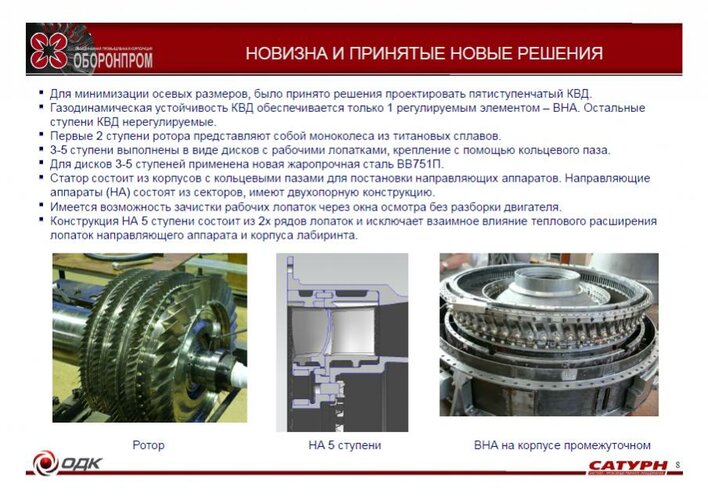
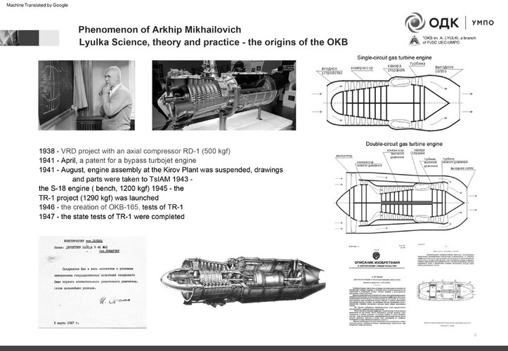
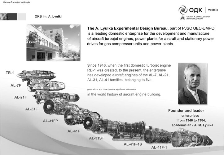
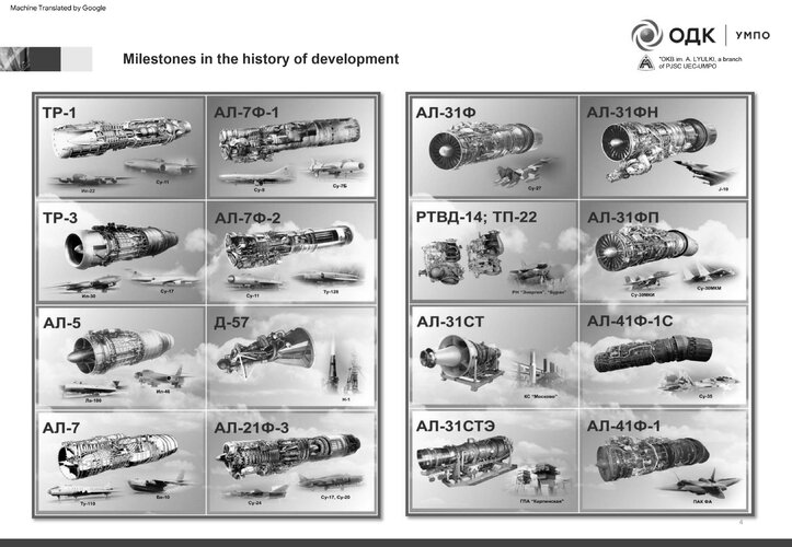
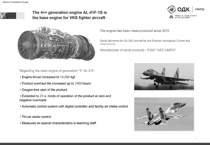
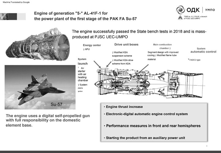
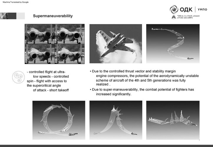
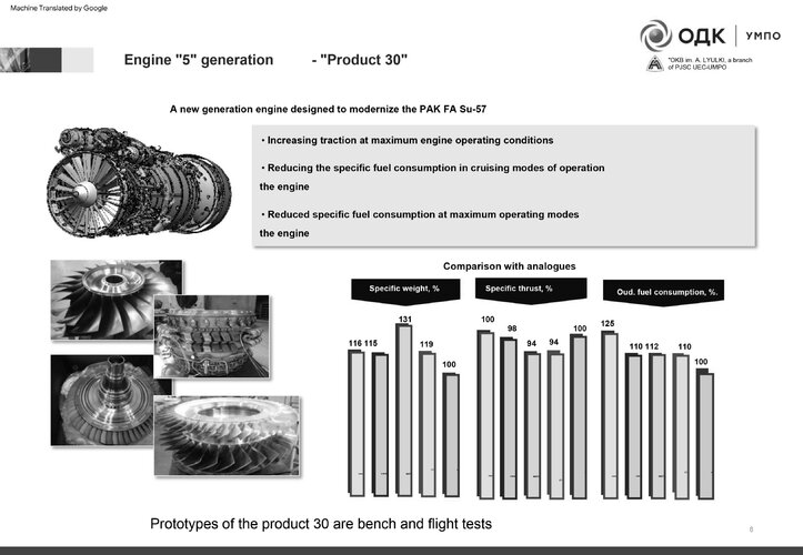
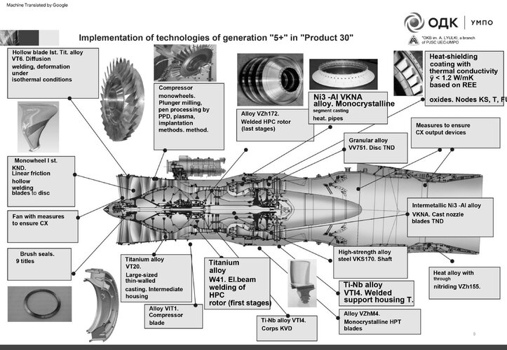
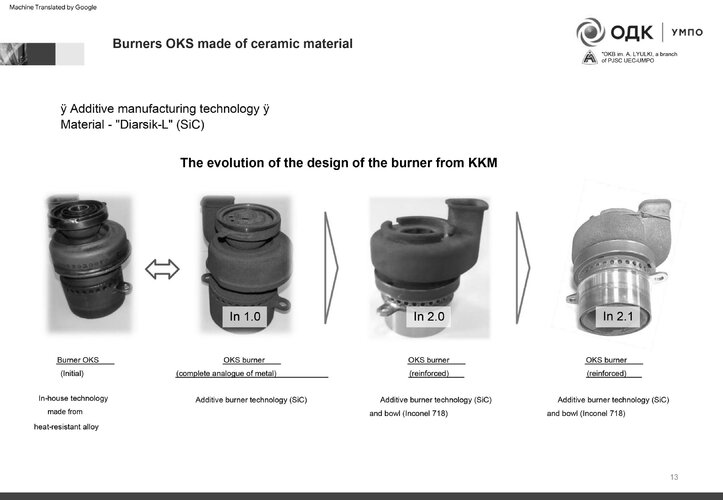
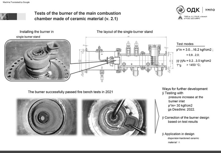
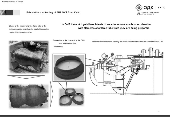
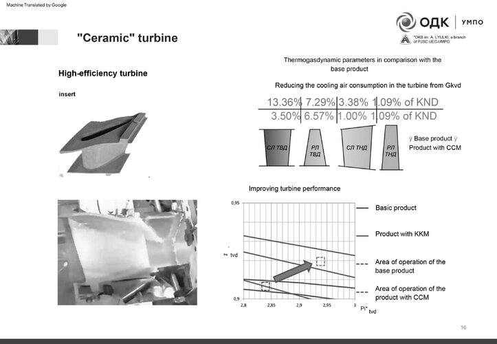
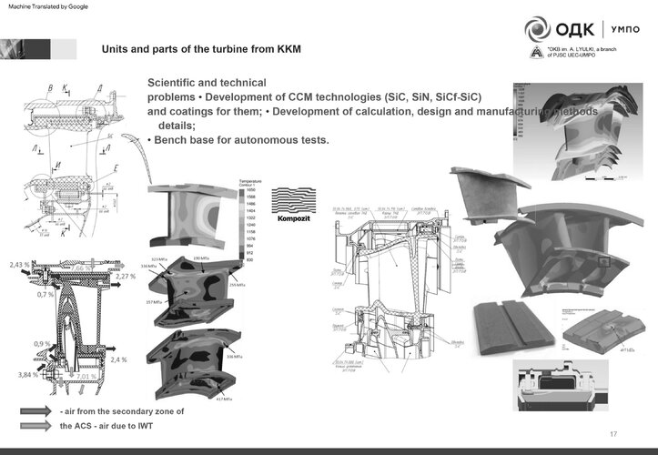
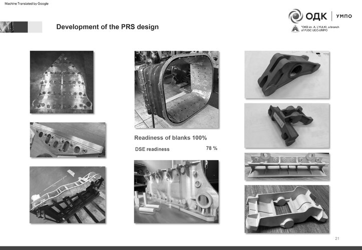
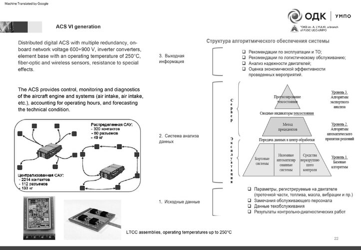
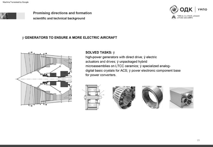
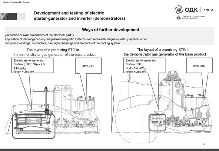
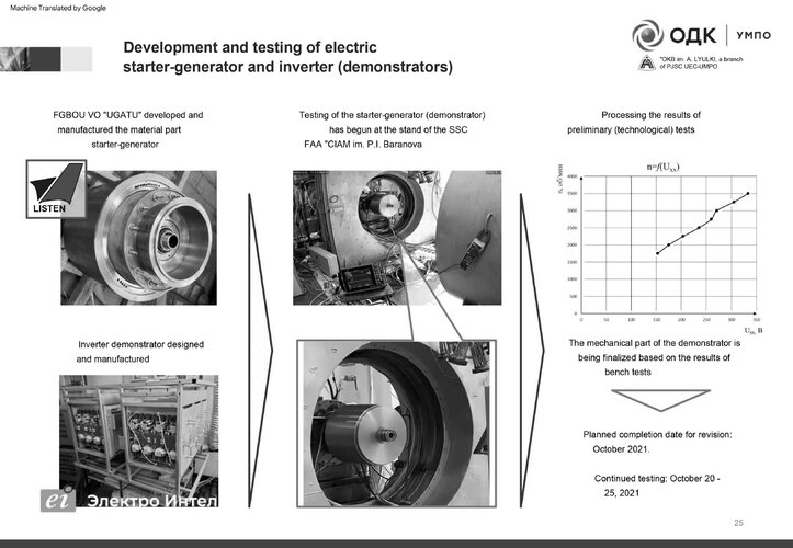
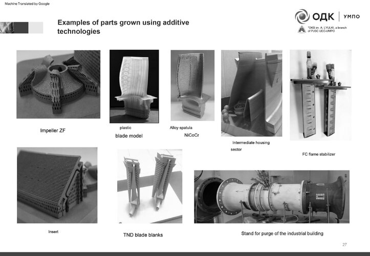
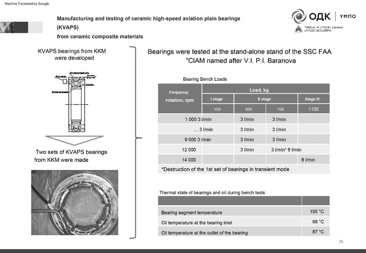
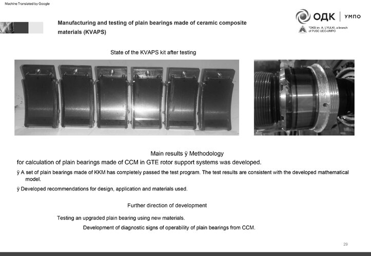
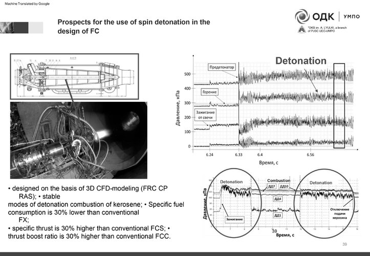
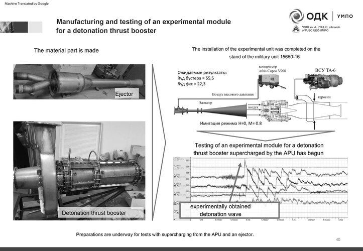
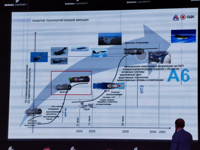
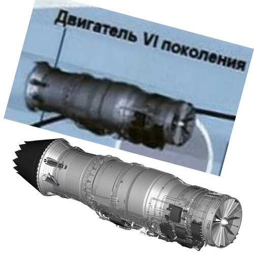
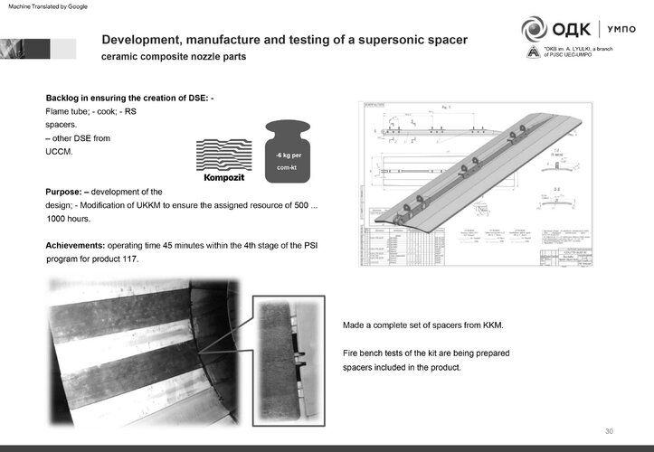
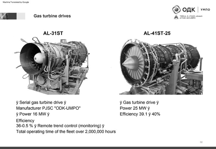
UMPO released a slide deck in November 2021 with some details on the izdeliye 30 as well as some of the comparisons with both the izdeliye 117 (AL-41F1) and analogues such as the F119-PW-100 (or, what they think its performance metrics are).

Page 8 contains comparisons of “specific gravity” (which in this case is likely the inverse of thrust-to-weight ratio), specific thrust, and specific fuel consumption, with the izdeliye 30 being considered the baseline value. In summary, compared to the AL-41F1, the izdeliye 30 has 16% lower “specific gravity” or 19% better thrust-to-weight ratio, 6.4% better specific thrust, and 9% lower SFC. Compared to the F119, the izdeliye 30 has 14% lower “specific gravity” or 16% better thrust-to-weight ratio, equivalent specific thrust, and 20% lower SFC, but I would take the F119 comparisons with some skepticism.

Based on the engine schematic as shown on page 9, it doesn’t appear to be a variable cycle engine, as there are no signs of a third stream or dual bypass channel and VABI-like constructs.
 

Attachments

  • Казань 10.11.21 г.pdf
    8.6 MB · Views: 512
Last edited:
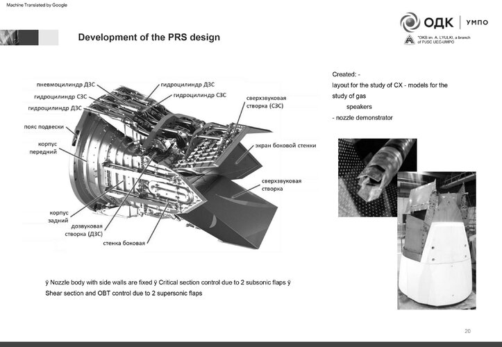
Great stuff. On page 20, is that the flat/LO nozzle for Su-57?!
That part on 26 is interesting. Looks like they're using the latest in part design. (The doc makes me wish I could read Russian. Looks very interesting.)
 
Does anyone have a Russian to English translator that would work on a PDF slide deck.

Admiring the pictures, I have a few observations:

- 3 stage blisk fan doe not appear to be designed for a pressure ratio much above 3.5 - 4:1 (eyeball estimate). Not what you want for a supercruise engine

- 4 stage high compressor- maybe 4:1 pressure ratio. Good for weight, not for SFC. May have very good compressor efficiency, Russians are known to be good aerodynamicists.

- Overall pressure ratio maybe 16:1 ? Not good for SFC. But low compression temperature rise leaves more room for heat addition in the main combustor below the TIT limit. Good for Mil thrust. If there is rotor speed margin and TIT margin to run faster / hotter under elevated inlet temperature conditions (roughly 100F at M1.5, 40k), helps with supersonic Mil thrust.

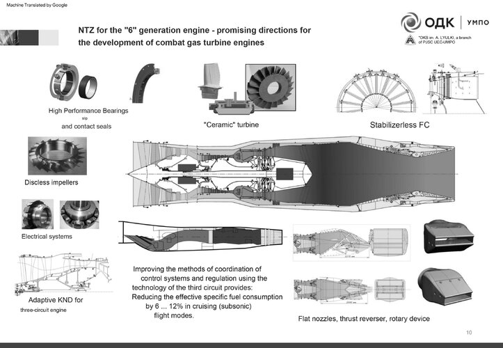
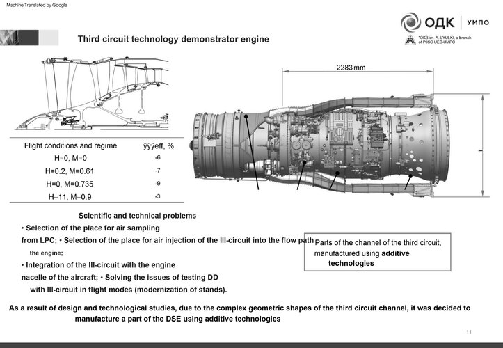
Page 10-11 shows a possible 3 stream variation for the engine. Also some LO inlet and exhaust concepts

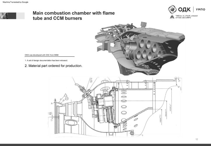
Page 12 - combustor design with radially staggered fuel nozzles. No indication how the combustor ID and OD wall are cooled.

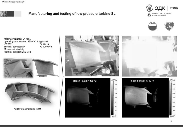
- Page 18 indicates a max temperature of 1350C. If that is the TIT limit, not very high compared to latest western engines

- Page 20 shows a 2D vectoring, possibly LO nozzle design
 
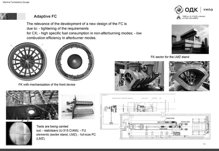
The doc is about a lot more than just Izd. 30 (basically just slides 8 & 9). 10 to 31 detail work on a 6th gen adaptive engine (which is interesting in its own right, of course!).
 
- 4 stage high compressor- maybe 4:1 pressure ratio. Good for weight, not for SFC. May have very good compressor efficiency, Russians are known to be good aerodynamicists.

Which engine are you referring to? The 5th gen Izd. 30 is known to have a 5-stage HPC (also shown that way in the schematic). Again, anything after slide 9 (and before #8) does not apply to Izd. 30.

- Page 18 indicates a max temperature of 1350C. If that is the TIT limit, not very high compared to latest western engines

Refers to testing of CMC LPT nozzle guide vanes, so not the engine TIT limit.
I’m counting 4 stages of HPC blades in the cross section. There is a 5th stage disk at the back end, but it appears to be holding a set of knife edge seals around the OD.

Edit: on Page 10, the upper half of the cross section shows a 4 stage compressor. But the bottom half shows a 5 stage compressor. They may be showing a design progression thru development. The pressure ratio seems to be consistent top to bottom, so they may have had a stall problem with the 4 stage design.

If that 1350C is the LPT inlet temp (see - I need that English translation!!), obviously the TIT is significantly higher - thanks for that clarification. With a low HPC pressure ratio, the temperature drop thru the HPT will be less (HPT temp drop roughly equal HPC temp rise) - don’t have a guess on what TIT will be with that info.

I haven’t gotten out my calipers, but you can estimate the Fan and HPC pressure ratio by comparing the inlet stage swept area to the exit area. At the design operating point, the local Mach number will remain relatively constant from the front to the back of the compressor. This is not perfect due to the changing temperature thru the compressor (which effects the local Mach number) but it is a reasonable first approximation.
 
Last edited:
I’m counting 4 stages of HPC blades in the cross section. There is a 5th stage disk at the back end, but it appears to be holding a set of knife edge seals around the OD.

Yes, I was counting discs, as in many such drawings the rear stages get really hard to discern. As you say though, that approach has its own pitfalls. The 5th disc is really close to the 4th, but if it isn't another rotor stage, why's the diffusor to the combustion chamber so long (it's really long even if we have 5 stages)?

Fortunately, we don't have to rely on this drawing, there were earlier leaked presentations that show the actual HPC rotor, with 5 stages clearly visible. I'll see if I can find them.

If that 1350C is the LPT inlet temp (see - I need that English translation!!),

No problem! I've actually not tried it yet, but Google Translate should be able to handle pdf documents:


I haven’t gotten out my calipers, but you can estimate the Fan and HPC pressure ratio by comparing the inlet stage swept area to the exit area. At the design operating point, the local Mach number will remain relatively constant from the front to the back of the compressor. This is not perfect due to the changing temperature thru the compressor (which effects the local Mach number) but it is a reasonable first approximation.

Makes sense. Given the questions about the geometric accuracy of the schematic mentioned earlier though, I'd be wary of using it to estimate such things. By all means do it and share the results please, but I suggest we do not put too much faith in the data.
 
I’m counting 4 stages of HPC blades in the cross section. There is a 5th stage disk at the back end, but it appears to be holding a set of knife edge seals around the OD.

Yes, I was counting discs, as in many such drawings the rear stages get really hard to discern. As you say though, that approach has its own pitfalls. The 5th disc is really close to the 4th, but if it isn't another rotor stage, why's the diffusor to the combustion chamber so long (it's really long even if we have 5 stages)?

Fortunately, we don't have to rely on this drawing, there were earlier leaked presentations that show the actual HPC rotor, with 5 stages clearly visible. I'll see if I can find them.

If that 1350C is the LPT inlet temp (see - I need that English translation!!),

No problem! I've actually not tried it yet, but Google Translate should be able to handle pdf documents:

Good luck. Here's what it did for me:

1687099390816.png
 
Edit: on Page 10, the upper half of the cross section shows a 4 stage compressor. But the bottom half shows a 5 stage compressor. They may be showing a design progression thru development. The pressure ratio seems to be consistent top to bottom, so they may have had a stall problem with the 4 stage design.
I don’t think the schematic on page 10 is the izdeliye 30, but rather a conceptual 6th generation development involving 3-stream adaptive cycle architecture, as the izdeliye 30 itself isn’t variable cycle. The schematic is on page 9, where I do see 5 HPC stages, although the last one is pretty hard to discern.
 
Last edited:
Edit: on Page 10, the upper half of the cross section shows a 4 stage compressor. But the bottom half shows a 5 stage compressor. They may be showing a design progression thru development. The pressure ratio seems to be consistent top to bottom, so they may have had a stall problem with the 4 stage design.
I don’t think the schematic on page 10 is the izdeliye 30, but rather a conceptual 6th generation development involving 3-stream adaptive cycle architecture, as the izdeliye 30 itself isn’t variable cycle. The schematic is on page 9, where I do see 5 HPC stages, although the last one is pretty hard to discern.
I meant page 9. It has the extra disk in the middle of the HPC on the lower half of the schematic
 

Attachments

  • Lyulka - 0001.jpg
    Lyulka - 0001.jpg
    362.8 KB · Views: 131
  • Lyulka - 0002.jpg
    Lyulka - 0002.jpg
    538.4 KB · Views: 116
  • Lyulka - 0003.jpg
    Lyulka - 0003.jpg
    527.1 KB · Views: 117
  • Lyulka - 0004.jpg
    Lyulka - 0004.jpg
    590 KB · Views: 115
  • Lyulka - 0005.jpg
    Lyulka - 0005.jpg
    391.8 KB · Views: 112
  • Lyulka - 0006.jpg
    Lyulka - 0006.jpg
    530.3 KB · Views: 107
  • Lyulka - 0007.jpg
    Lyulka - 0007.jpg
    403 KB · Views: 103
  • Lyulka - 0008.jpg
    Lyulka - 0008.jpg
    454.6 KB · Views: 115
  • Lyulka - 0009.jpg
    Lyulka - 0009.jpg
    641.5 KB · Views: 127
  • Lyulka - 0010.jpg
    Lyulka - 0010.jpg
    478.6 KB · Views: 129
More
 

Attachments

  • Lyulka - 0011.jpg
    Lyulka - 0011.jpg
    477.6 KB · Views: 115
  • Lyulka - 0012.jpg
    Lyulka - 0012.jpg
    384.8 KB · Views: 92
  • Lyulka - 0013.jpg
    Lyulka - 0013.jpg
    302.2 KB · Views: 83
  • Lyulka - 0014.jpg
    Lyulka - 0014.jpg
    491.9 KB · Views: 84
  • Lyulka - 0015.jpg
    Lyulka - 0015.jpg
    442.3 KB · Views: 85
  • Lyulka - 0016.jpg
    Lyulka - 0016.jpg
    325.2 KB · Views: 82
  • Lyulka - 0017.jpg
    Lyulka - 0017.jpg
    448.4 KB · Views: 85
  • Lyulka - 0018.jpg
    Lyulka - 0018.jpg
    324 KB · Views: 89
  • Lyulka - 0019.jpg
    Lyulka - 0019.jpg
    526.9 KB · Views: 99
  • Lyulka - 0020.jpg
    Lyulka - 0020.jpg
    404.1 KB · Views: 102
and more
 

Attachments

  • Lyulka - 0021.jpg
    Lyulka - 0021.jpg
    398.1 KB · Views: 93
  • Lyulka - 0022.jpg
    Lyulka - 0022.jpg
    435.8 KB · Views: 85
  • Lyulka - 0023.jpg
    Lyulka - 0023.jpg
    314.5 KB · Views: 82
  • Lyulka - 0024.jpg
    Lyulka - 0024.jpg
    573.3 KB · Views: 78
  • Lyulka - 0025.jpg
    Lyulka - 0025.jpg
    477.2 KB · Views: 69
  • Lyulka - 0026.jpg
    Lyulka - 0026.jpg
    427.6 KB · Views: 68
  • Lyulka - 0027.jpg
    Lyulka - 0027.jpg
    375.6 KB · Views: 69
  • Lyulka - 0028.jpg
    Lyulka - 0028.jpg
    408.9 KB · Views: 71
  • Lyulka - 0029.jpg
    Lyulka - 0029.jpg
    384.1 KB · Views: 70
  • Lyulka - 0030.jpg
    Lyulka - 0030.jpg
    386.8 KB · Views: 77
and last
 

Attachments

  • Lyulka - 0031.jpg
    Lyulka - 0031.jpg
    480.6 KB · Views: 78
  • Lyulka - 0032.jpg
    Lyulka - 0032.jpg
    417 KB · Views: 77
  • Lyulka - 0033.jpg
    Lyulka - 0033.jpg
    486.8 KB · Views: 70
  • Lyulka - 0034.jpg
    Lyulka - 0034.jpg
    427.3 KB · Views: 67
  • Lyulka - 0035.jpg
    Lyulka - 0035.jpg
    327.9 KB · Views: 67
  • Lyulka - 0036.jpg
    Lyulka - 0036.jpg
    492.2 KB · Views: 70
  • Lyulka - 0037.jpg
    Lyulka - 0037.jpg
    517.9 KB · Views: 71
  • Lyulka - 0038.jpg
    Lyulka - 0038.jpg
    353.9 KB · Views: 77
  • Lyulka - 0039.jpg
    Lyulka - 0039.jpg
    600 KB · Views: 77
  • Lyulka - 0040.jpg
    Lyulka - 0040.jpg
    524.2 KB · Views: 92
  • Lyulka - 0041.jpg
    Lyulka - 0041.jpg
    194.2 KB · Views: 105
From here :

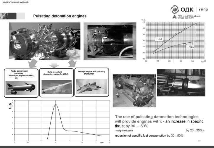
Related to work on PDE but also contain that nice image of engine for S-70. But there is also this :

FzV7WAWaYAAtHSj


FzV8R-FaIAEbjwn


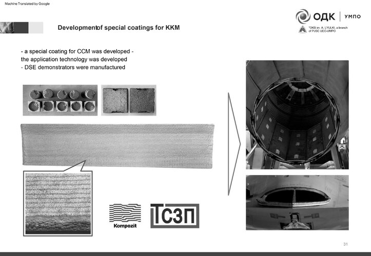
Basically some details of work regarding Engine RCS reduction and development of related software package to help refining the engine.

For now the design seems to revolve on material to cover the nozzle petals. But looking at the Phenom (Phenomonology Model) seems coating of the afterburning chamber could be possible. I'm curious tho if Russia would follow the F-22 and F-35 example by putting special device to shield the rotating turbine.

The RAM being used is likely to be based on Silicone carbide or other high temperature RAM, as Magnetic RAM may be sensitive to temperature which affect their magnetic properties.
 
Page 8 contains comparisons of “specific gravity” (which in this case is likely the inverse of thrust-to-weight ratio),
Yes, as far as I know they use that metric as the inverse of TWR

Compared to the F119, the izdeliye 30 has 14% lower “specific gravity” or 16% better thrust-to-weight ratio, equivalent specific thrust, and 20% lower SFC,
I read 16% lower specific gravity, same specific thrust and 25% lower SFC (?). They stated they had the highest specific thrust, so they probably aimed at "equal or better" perfomance in that regard that their reference F119

Based on the engine schematic as shown on page 9, it doesn’t appear to be a variable cycle engine, as there are no signs of a third stream or dual bypass channel and VABI-like constructs.
VCE is not the same as three stream engine, or am I wrong?

Regardless, this is the first high quality, conclusive information we get about the engine, it is a great find

- Overall pressure ratio maybe 16:1 ? Not good for SFC. But low compression temperature rise leaves more room for heat addition in the main combustor below the TIT limit. Good for Mil thrust. If there is rotor speed margin and TIT margin to run faster / hotter under elevated inlet temperature conditions (roughly 100F at M1.5, 40k), helps with supersonic Mil thrust.
What do you make of the figures in the comparison? Do you have any idea of how they achieve such high specific thrust / TWR and low SFC? Are those values maybe comparable to those of F135? I am calculating TWR around 12:1, equivalent to that of F135, but I guess specific thrust of the later is lower than that of the F119?
 
Last edited:
I read 16% lower specific gravity, same specific thrust and 25% lower SFC (?). They stated they had the highest specific thrust, so they probably aimed at "equal or better" perfomance in that regard that their reference F119
Read the chart again. It claims that compared to the izdeliye 30, the F119 has 16% higher specific gravity, so taking the inverse means 14% lower. Similarly, the inverse of 25% higher is 20% lower. Saturn will try to design the engine to have the specific thrust necessary to meet the requirements, but their comparative statements with the F119 and other foreign engines should be taken with caution as they likely don't have the full specs.

VCE is not the same as three stream engine, or am I wrong?
Variable cycle doesn't necessarily mean three-stream; the YF120 (GE37) architecture consists of two bypass channels around the last stage of the fan, also called the core-driven fan stage. Opening or closing the aft bypass channel is how variability of bypass ratio is achieved. The diagram of the izdeliye 30 doesn't have anything like this, nor a three-stream fan, and the latter was only presented in a following slide as a potential further development.
 
Last edited:
Bear in mind there's no detail here, and we have no idea if Sukhoi have accurate figures for F119 engine. 20% lower SFC in which flight regime?
 
Read the chart again. It claims that compared to the izdeliye 30, the F119 has 16% higher specific gravity, so taking the inverse means 14% lower. Similarly, the inverse of 25% higher is 20% lower. Saturn will try to design the engine to have the specific thrust necessary to meet the requirements, but their comparative statements with the F119 and other foreign engines should be taken with caution as they likely don't have the full specs.
Ouch, that was pretty silly from me... Yes, we don't know the quality of their intelligence about foreign products, nor how much they are wanting to say. Would love to see the comparison to F135, which is the more recent engine despite not being designed for supercruise

Variable cycle doesn't necessarily mean three-stream; the YF120 (GE37) architecture consists of two bypass channels around the last stage of the fan, also called the core-driven fan stage. Opening or closing the aft bypass channel is how variability of bypass ratio is achieved. The diagram of the izdeliye 30 doesn't have anything like this, nor a three-stream fan, and the latter was only presented in a following slide as a potential further development.
Yes agree, nothing clearly stands out as indicating variable bypass, so Marchukov's previous statements remain puzzling to me. Still is difficult for me to understand the technological status of their development, specifically, from where do the performance gains come from when compared to the previous generation. It was always stated that to achieve significantly better SFC and high specific thrust VCE was necessary.

Bear in mind there's no detail here, and we have no idea if Sukhoi have accurate figures for F119 engine. 20% lower SFC in which flight regime?
They mention maximum and cruise SFCs in that very slide, which is the one that applies to the chart is unclear, but my guess would be subsonic cruising. Why would the F119 have such a high SFC in AB? Specific gravity should de be referred in max and specific thrust in mil power, that would be my understanding.
 
Chart sees to show two engines, AL-51-F1 (which looks identical to AL-41-F1) and then the one above and to the right with the 2D exhaust. This looks rather different. I'd guess this is Izdeliye 30 and AL-51-F1 is an improved AL-41-F1 for e.g. Checkmate.
 
Last edited:
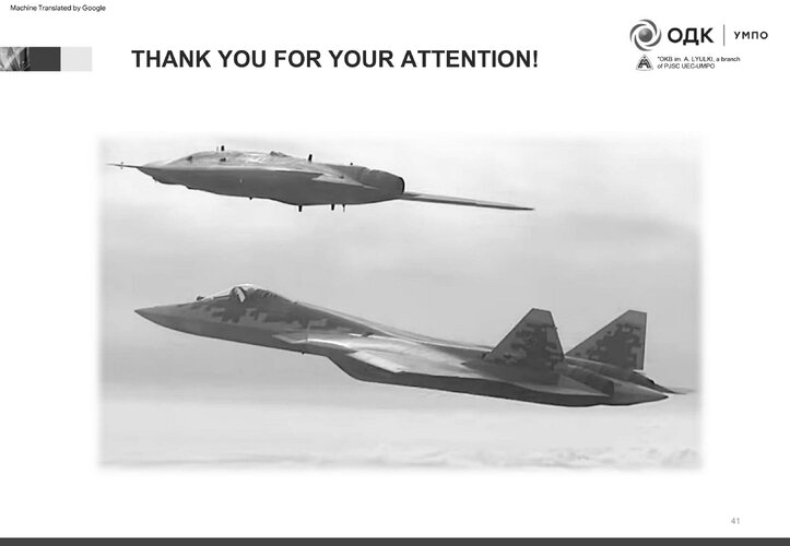
Yeah the imageries are basically placeholders.. which also include US 5th Gen decoy, MiG-29 which Lyulka wont touch and Aussie-Boeing drone which use something in class of RD-133.
 
Now that I am home with large screen and a caliper. This has the proviso that I am assuming that the cross section on Page 9 is accurate and to scale. Typical Fan / Compressor design is for the airflow Mach number to remain relatively constant thru the Fan / Compressor at Mil power. Variable inlet vanes or bleeds are used to reduce the airflow to the back of the compressor at lower speeds where the compression ratio is much lower than the inlet to exit mechanical area ratio.

- 3 stage blisk fan has an inlet to exit area ratio of 3:1. Compression increases the temperature of the air, which tries to expand with the ratio of the absolute temperature rise (theta), but the speed of sound increases with the square root of theta. Holding the air Mach number constant thru the Fan, and ratioing some other similar fans, I estimate a fan pressure ratio of approx 4.1 - 4.2 to one. Similar to the F414 and EJ200, possibly good for low Mach supercruise (M1.2-1.4)

- 5 stage high compressor- Measured the upper half of the schematic with the 4 stage compressor, assuming the schematic lower half 5 stage compressor (not visible behind the graphic markers) has the same inlet to exhaust area ratio of 2.75:1. Maybe a 4:1 pressure ratio, probably less. . Good for weight, not for SFC. May have very good compressor efficiency, Russians are known to be good aerodynamicists and less pressure ratio is good for compression efficiency.

- High compressor mid stage bleed is piped to the Low Turbine Vanes and Blades for cooling. This air is cooler than compressor exit temperature - better cooling and less performance penalty than taping the LPT cooling air from the compressor exit. This also acts as a passive variable bleed for engine start and low power (high percentage compressor bleed at low power, less when flow to LPT is choked at high power.

- Overall pressure ratio maybe 16:1 to 18:1? Not good for SFC. But low compression temperature rise leaves more room for heat addition in the main combustor below the TIT limit. Good for Mil thrust. If there is rotor speed margin and TIT margin to run faster / hotter under elevated inlet temperature conditions (roughly 100F at M1.5, 40k), helps with supersonic Mil thrust. The Soviets used a similar low overall pressure ratio in their MiG-21 turbojet engines.

- Based on the intermediate case splitter area ratio and splitter orientation to the fan discharge flow, it looks like a 0.40 bypass ratio. Better for Mil SFC than F414 or EJ200 or the reported BPR of the F119, better augmentation thrust ratio, worse for supercruise. Bypass ratio can change depending on nozzle closure fan pressure ratio up-match, but only so much.

- Mixed flow afterburner - the cross section shows a fan bypass and core flow going thru a lobed mixer prior to the augmentor flameholder, similar to the F110 engine.

- Spray bars / Spray rings (unsure on design) behind a stand alone flameholder. Similar to legacy engines, definitely not an LO solution.

- Convergent / Divergent nozzle with a decent length divergent section, not an ejector nozzle. If the divergent area can be set independently to the convergent area, or there is some passive floating divergent area ratio variability, this helps supercruise. If the divergent area is a fixed ratio to the convergent area, there are compromises between subsonic and supersonic thrust.

Overall, the engine appears to be similar in performance potential to the F414 or EJ200, except bigger (higher airflow). I am not seeing support for the high specific thrust at supercruise warm inlet conditions, nor for the SFC claims. There are a lot of engine design tradeoffs, so it is difficult to determine which characteristics dominate the performance of the Product 30.
 
With the kinds of aerospace firms working on this project, I'd say it is safe to trust in the goals they have stated until told otherwise. Also I highly doubt they would play show and tell with the innards of the izd 30 even with simple pictures and descriptions. I may be wrong though, obviously.
 
Now that I am home with large screen and a caliper. This has the proviso that I am assuming that the cross section on Page 9 is accurate and to scale. Typical Fan / Compressor design is for the airflow Mach number to remain relatively constant thru the Fan / Compressor at Mil power. Variable inlet vanes or bleeds are used to reduce the airflow to the back of the compressor at lower speeds where the compression ratio is much lower than the inlet to exit mechanical area ratio.

Thanks! Very interesting. Some comments below.

- 3 stage blisk fan has an inlet to exit area ratio of 3:1. Compression increases the temperature of the air, which tries to expand with the ratio of the absolute temperature rise (theta), but the speed of sound increases with the square root of theta. Holding the air Mach number constant thru the Fan, and ratioing some other similar fans, I estimate a fan pressure ratio of approx 4.1 - 4.2 to one. Similar to the F414 and EJ200, possibly good for low Mach supercruise (M1.2-1.4)

I've been trying to extrapolate Izd. 30 performance based on open-source data available on other clean-sheet, new-generation Russian engines and demonstrator turbomachinery. As a lower bound, I got the same kind of LP compressor PR. As an aside, if you say 4.2 is only sufficient for at most Mach 1.4 supercruise, what's the PR of the F119 LPC, if that is publicly releasable info? It also has a 3-stage fan, and otherwise does not seem to have especially high stage-PRs compared to the EJ200 with a 4.2 ratio for its LPC.

Worth noting that the KND-924-3 blisk LPC upgrade for the AL-31FM was already supposed to hit a 4.2 ratio 20 years ago. So with advances in the state of the art in the mean time, I expect this to be firmly the lower bound, as mentioned.

- 5 stage high compressor- Measured the upper half of the schematic with the 4 stage compressor, assuming the schematic lower half 5 stage compressor (not visible behind the graphic markers) has the same inlet to exhaust area ratio of 2.75:1. Maybe a 4:1 pressure ratio, probably less. . Good for weight, not for SFC. May have very good compressor efficiency, Russians are known to be good aerodynamicists and less pressure ratio is good for compression efficiency.

- Overall pressure ratio maybe 16:1 to 18:1? Not good for SFC. But low compression temperature rise leaves more room for heat addition in the main combustor below the TIT limit. Good for Mil thrust. If there is rotor speed margin and TIT margin to run faster / hotter under elevated inlet temperature conditions (roughly 100F at M1.5, 40k), helps with supersonic Mil thrust. The Soviets used a similar low overall pressure ratio in their MiG-21 turbojet engines.

It's definitely going to be a 5-stage machine. Other than that, I think this is almost certainly low-balling the HPC PR. From the performance achieved in the civilian PD-14 compressor, various research projects and a 6-stage core upgrade for the ultimate AL-31FM3 that targeted 6.7, i'd expect a PR of at least 6.2 (like the 5-stage EJ200). Possibly as high as 7.0 as an upper bound (but that is pushing it on OPR, leading to high compressor exit temps for an engine behind a supersonic intake).

Might the temperature rise over a machine with a relatively high number of stages and a high PR skew your geometrical method here?

- Based on the intermediate case splitter area ratio and splitter orientation to the fan discharge flow, it looks like a 0.40 bypass ratio. Better for Mil SFC than F414 or EJ200 or the reported BPR of the F119, better augmentation thrust ratio, worse for supercruise. Bypass ratio can change depending on nozzle closure fan pressure ratio up-match, but only so much.

Plausible. My gut instinct is also that the Russians would not go quite as low with BPR as the F414, M88 or F119, given a fairly high emphasis on SFC in their statements about the design. So nearer to 0.4 (akin to the EJ200) than 0.3 or less seems about right.

- Spray bars / Spray rings (unsure on design) behind a stand alone flameholder. Similar to legacy engines, definitely not an LO solution.

The rear of the engine schematic looks suspiciously like the legacy AL-31F (nozzle design, AB flame holders, turbine exit cone), so that might be a place holder. When images were first leaked of the LO nozzle on an uninstalled Izd. 30, the interior was censored, obscuring the AB flame holder design and possible LO measures. It's conceivable that these are considered sensitive and therefore not shown.

- Convergent / Divergent nozzle with a decent length divergent section, not an ejector nozzle. If the divergent area can be set independently to the convergent area, or there is some passive floating divergent area ratio variability, this helps supercruise. If the divergent area is a fixed ratio to the convergent area, there are compromises between subsonic and supersonic thrust.

Fairly safe bet that there will be independent A8/A9 control given the emphasis on supersonic performance - the AL-31F nozzle already had this.
 

Similar threads

Please donate to support the forum.

Back
Top Bottom