Perhaps the easiest full-scale F-47 look-alike TD/prototype modified from existing jet F-22.
The wing & tail-stab positions are interchanged & rudders removed.
It is a quick, simple,notional edit, many small flaws can be observed by people into 3D CAD.
Making its front, side, bottom views w/o 3D S/w by just imagining is very tedious at this time, what i used to do on graph sheets in school-days in 1990s watching F-117, B-2, developing F-22 on Discovery channel. The good old days
Anyways, i wonder if LM built such a jet for competition or research.
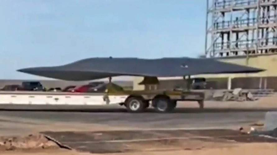
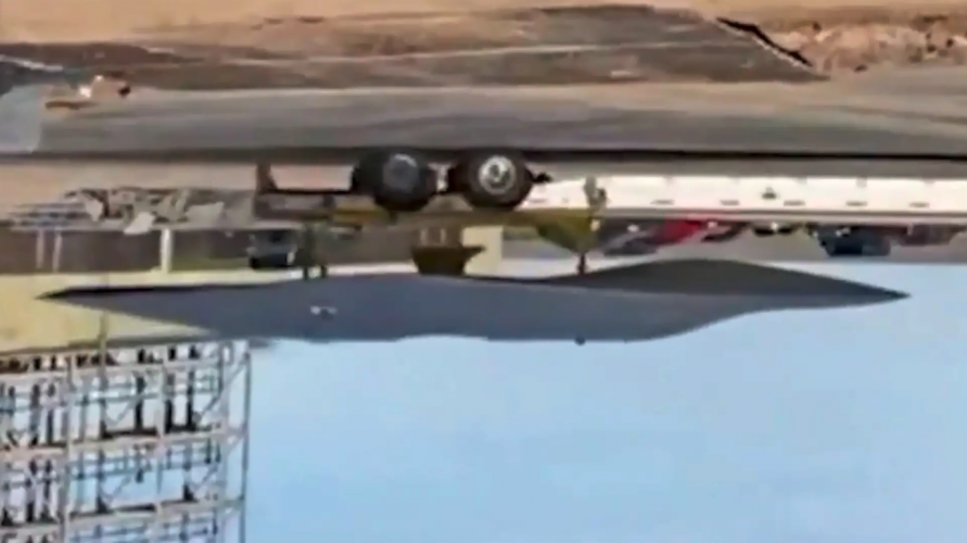
It remains unidentified. Its simplified form - no visible inlets/exhaust or canopy other than a bulge - makes me think that it's a scale display model, along the lines of the GCAP model that appeared at Farnborough.
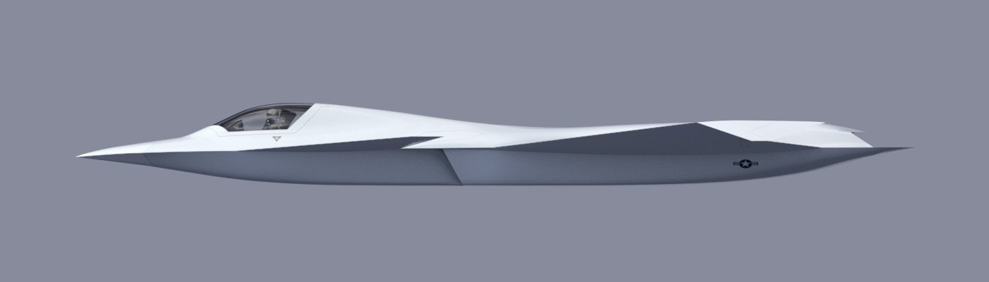
I believe I'm quite safe, after all the only parts that I'm confident about are the ones that I've highlighted in green below:
Dimensions, angles and everything not immediately visible from the pictures released so far (i.e. from the start of the wing onward towards the exhausts) are purely speculative, albeit based on concepts and studies done by Boeing.
More than a NGAD speculative configuration, mine is a NAD speculative configuration (Not Another Delta or Not Another Dorito).
Perhaps the easiest full-scale F-47 look-alike TD/prototype modified from existing jet F-22.
The wing & tail-stab positions are interchanged & rudders removed.
It is a quick, simple,notional edit, many small flaws can be observed by people into 3D CAD.
Making its front, side, bottom views w/o 3D S/w by just imagining is very tedious at this time, what i used to do on graph sheets in school-days in 1990s watching F-117, B-2, developing F-22 on Discovery channel. The good old days
Anyways, i wonder if LM built such a jet for competition or research.
That's not going to fly right, the main wings are too far aft. Center of lift is 1/3 of the way down the chord line while subsonic, 1/2 chord while supersonic. I'm putting the rough center of lift on the main wings to be at the point of the skin line of the exhaust nozzles on your sketch. So if it's using F-22 wings, the engines would need to extend well aft of them for rough balance.
I'm suspecting that the LockMart proposal looked a lot like the FB-22 or X-44. Giant delta wing on a plane that basically has a second F-22 weapons bay added aft of the first one.
Well, as i said this is just quick notional edit for a TD (Tech. Demonstrator), an eyecandy, adding to the guessing fun, before the prototype gets revealed in a ceremony & we start getting documentaries on NGAD.
I did this after noticing the X-36, Bird of Prey, J-20, other delta-canards like Rafale, EF-2000, Gripen, Vigen, Draken, etc.
AFAIK, most of the individually thought 3D CAD models are similar. No artist has presented calculations of C.o.G., C.o.L. etc. Very few even mention the dimensions.
IDK if the C.o.L. shifts back with speed.
1 thing i know is for unstable jet the C.o.G. is little behind the C.o.L. & vice-versa for stable jet:
I read that modern fighter jets need to be designed unstable for agility & controlled by avionics computers.
So let's assume that C.o.L. will be litlle ahead of C.o.G.
IDK formula for C.o.L. but for a simple scalene triangle C.o.G. is on Centroid which is 2/3rd of length from forward tip & 1/3rd of height/width outward from base:
But finding C.o.G. of aircraft is complex bcoz the mid-fuselage has hollow ducts but not the aft fuselage with engines. The equipments & fuel tanks are smeared all over the airframe.
To make things little easy, the C.o.G. should be ahead of main/rear landing gear or the plane will tip over backwards.
So in the modified design, exchanging the wings & tail-stab positions, shifts the airframe Co.G. backward a lot.
> hence i didn't move the engine as it'll complicate things for me, shifting the C.o.G. back more.
> pushing the canard (tail-stab) little forward shifts the C.oG. & C.o.L. little forward to balance wing.
> removing rudder lightens rear fuselage & shifts the C.o.G. forward.
> adding chines to nose will move the C.o.G. little forward. It may also add to lift.
> if the MLG is also pushed back then it shifts C.oG. little back but also the fulcrum back, it should prevent the plane from tipping over back. I did this in the side & bottom views but didn't share them bcoz it is incomplete, imagining the forward fuselage area is complex. Intake area has to be maintained which affects nose shape. The following is the incomplete diagram with MLG shifted back:
Perhaps the canards should be shifted more forward & wing lengthened, leading edge sweep angle increased.
That's all my low IQ brain can think of. LOL!
I'll try a V2 of these diagrams.
But to translate this into a flyable jet's diagram will need a S/w which can input the density of structure, weight of components & will tell us the computed output of C.o.G. at least. IDK if 3D CAD S/w like Blender, Fusuion360, etc can do it.
That's not going to fly right, the main wings are too far aft. Center of lift is 1/3 of the way down the chord line while subsonic, 1/2 chord while supersonic. I'm putting the rough center of lift on the main wings to be at the point of the skin line of the exhaust nozzles on your sketch. So if it's using F-22 wings, the engines would need to extend well aft of them for rough balance.
I'm suspecting that the LockMart proposal looked a lot like the FB-22 or X-44. Giant delta wing on a plane that basically has a second F-22 weapons bay added aft of the first one.
The wing may not be as far off as you may think. The center of lift (subsonic) on the wing is 25% MAC. The forebody and canard are extremely destabilizing, probably 20 to 25%. That would place the neutral point near the leading edge or just off. Given negative stability (subsonic) is desired, that would place the CG between 0 and 10% MAC. The big question is whether the engines need to move aft ( probably so). I wouldn't be surprised at the end of the day, the canard and wing would need to move forward in unison.
By the way, the Lockheed submittal used a hybrid cranked arrow.
This site uses cookies to help personalise content, tailor your experience and to keep you logged in if you register.
By continuing to use this site, you are consenting to our use of cookies.