Possible configuration of the Boeing F-47 NGAD

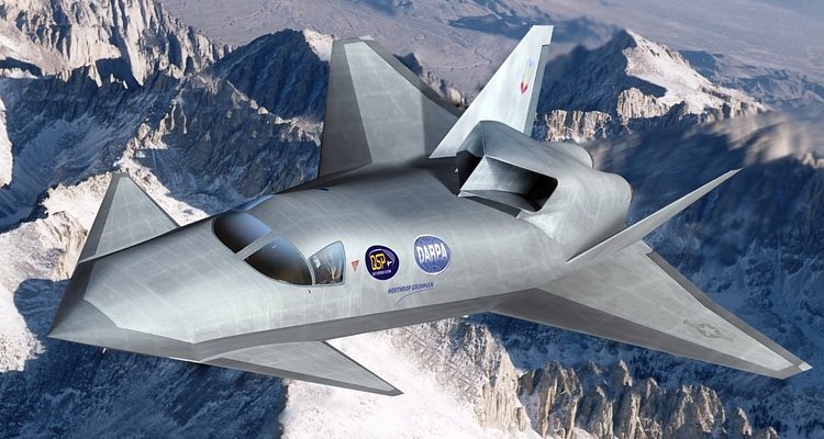
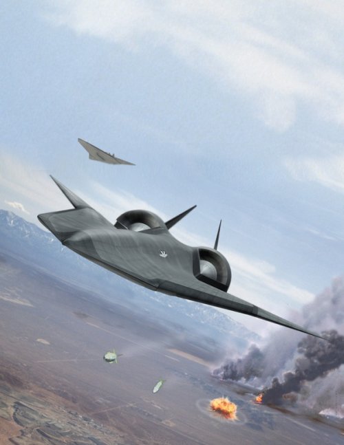
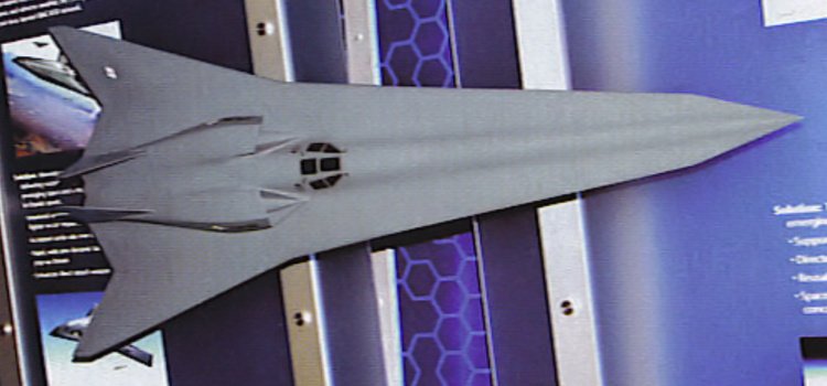
The shovel nose was tickling my brain and these images of studies into a 'Quiet Supersonic Platform' eventually emerged from the Carboniferous stratum of my memory - the early 2000s, that is. Most quiet supersonic studies have been needle-like but that might compromise military requirements, so a shovel nose was resurrected. If all-aspect stealth is required, then suppression of boom is included, and reduced wave drag also helps.

From Northrop Grumman initially - QSP and Long Range Strike concepts. Maybe someone was headhunted by Boeing.
 

Attachments

  • space0202super_A2.gif
    space0202super_A2.gif
    14.2 KB · Views: 42
  • northrop_qsp_early.jpg
    northrop_qsp_early.jpg
    162.5 KB · Views: 34
  • NGLRS - supersonic unmanned.jpg
    NGLRS - supersonic unmanned.jpg
    112 KB · Views: 34
  • northrop_grumman_long_range_strike_3 2.jpg
    northrop_grumman_long_range_strike_3 2.jpg
    101.3 KB · Views: 38
Last edited:
To the guy that made the rendering for the Air Force: I dislike you with a passion, Sir/Madam.
View attachment 765084
The amounts of shift and tilt applied to the camera are diabolical.
And I'm still not 100% sold on the combination of both with the camera position.
Excellent work!!! I think you nailed the nose shape. The camera work you did for comparison is spectacular!!! And if you were able to match the shape in both images of the F47, it must be the closest thing to its real design.
I have a technical question: as a mesh smoothing modifier, do you use Turbosmooth/Meshsmooth or OpenSudivs?
I've never used OpenSudivs, but they say it does a great job.
Regards and congratulations again on your work!!!
 
Excellent work!!! I think you nailed the nose shape. The camera work you did for comparison is spectacular!!! And if you were able to match the shape in both images of the F47, it must be the closest thing to its real design.
I don't think I did enough though.

There are still some significant misalignments that I've been, so far, unable to correct:
Speculative F-47 - V5.00 - 4a.jpg
Speculative F-47 - V5.00 - 5a.jpg

I'm at a bit of an impasse here as it appears that the image has been distorted with further parameters besides those that I've been fighting up against until now.
And even a small misalignment can make significant changes to the overall shape, see for example how much different these 2 screenshots look:
Speculative F-47 - V5.00 - 3.jpg
Speculative F-47 - V5.00 - 6.jpg
Both align pretty well with the official images released when seen from the same frontal camera I used above and yet, just a small variation by moving a vertex up or down requires another movement on the other 2 axes to match the views.
With extremely significant changes on the final shape.

It's been a lot of trial and error so far, so I might need to let a few days pass by and then come back to the problem to see if I can look at it from a different approach.

I have a technical question: as a mesh smoothing modifier, do you use Turbosmooth/Meshsmooth or OpenSudivs?
I use NURMS for my final models.
But in the above pictures I'm just going back and forth with low poly meshes adding and removing the smooth modifier.

Regards and congratulations again on your work!!!
Cheers! Thank you
 
I don't think I did enough though.

There are still some significant misalignments that I've been, so far, unable to correct:

I'm at a bit of an impasse here as it appears that the image has been distorted with further parameters besides those that I've been fighting up against until now.
And even a small misalignment can make significant changes to the overall shape, see for example how much different these 2 screenshots look:

Both align pretty well with the official images released when seen from the same frontal camera I used above and yet, just a small variation by moving a vertex up or down requires another movement on the other 2 axes to match the views.
With extremely significant changes on the final shape.

It's been a lot of trial and error so far, so I might need to let a few days pass by and then come back to the problem to see if I can look at it from a different approach.

I use NURMS for my final models.
But in the above pictures I'm just going back and forth with low poly meshes adding and removing the smooth modifier.

Cheers! Thank you

Great analysis!

What nose / canard / wing sweep angle does this result in? I think a leading edge sweep similar to the F-22 would be reasonable. Maybe you could apply that angle to your model and then try to line it up with the F-47 images?
 
I agree, f22 or yf23 wing sweep is very likely. You gotta do some assumptions which are logical. Also, observe f22, f35 from the side. Nose chine line from the nose tip to the intakes goes upwards. Curiously, on yf23 the upward line is minimal.

Also, every aircraft will have the wing surface point slightly downward, due to angle of attack needs.
If you look at side view of f22 you will see that, relative to the ground, not only is nose chine line going slightly upward but the wing surface points slightly downwards, when looked from leading to trailing edge.
 
To the guy that made the rendering for the Air Force: I dislike you with a passion, Sir/Madam.
View attachment 765084
The amounts of shift and tilt applied to the camera are diabolical.
And I'm still not 100% sold on the combination of both with the camera position.
I'm certain that was deliberate, to prevent exactly the type of work you're doing.


I am not doubting your work in terms of where the canards are, but man they're in a terrible spot. Blocking views out the canopy to the sides and below. There must be a DAS sensor covering that arc on each side.
 
What nose / canard / wing sweep angle does this result in? I think a leading edge sweep similar to the F-22 would be reasonable. Maybe you could apply that angle to your model and then try to line it up with the F-47 images?
At the moment, I'd say the angle is not "realistic":
Speculative F-47 - V5.00 - 7.jpg

BTW, going over Boeing's patent posted in the NGAD thread I'm starting to see some similarities with previously posted material. The main difference, so far and at least for the frontal section only (which is what I've modeled here), appears to be the position of the canards.
 
Surprisingly good model and logical enough, even if some close details could be corrected. It's the same guy who made J-50 and J-36 CGIs. It's almost like a sort of 6th generation J-20, the relatively long fuselage being optimized for lower drag, increased range and supercruise, which are some of the parameters the F-47 is said to be above the earlier generation.
 
"Mom get the camera! People are posting my stuff on Twitter!"

Still working on the assumption that the Two-o-thunder patch might be relevant:
View attachment 764790
View attachment 764791
View attachment 764792

Without knowing the specific FOV of the camera used for taking the shots of the renderings that have been released so far, it will be quite difficult to get an accurate match.

Seen from above, everything is planform aligned along 4 angles, but without knowing more I'm not sure I can do much else.
It is indeed speculative.
It's mostly a mix of the silhouette seen in the patch, hints from the pictures released and inspiration taken from Boeing's Concept 2405 and 2409.
I have the feeling you are near of the real configuration
 
Not sure if the theory around those blobs is accurate but I kind of like the idea though wouldn't that put them way a bit further aft of the canopy than the graphic above?
 
Last edited:
Could be covering dorsal inlets while trying to look like they aren't covering dorsal inlets (i.e. using blobs)
Second rendering shows fuselage top area well behind wing leading edge with no sign of any inlets.
 
I'm fairly sure that it's gonna be a single seater:
Speculative F-47 - V6.00 - 1a.png
Speculative F-47 - V6.00 - 3a.png
Still struggling with trying to understand the canards' shape, though...
 

Similar threads

Please donate to support the forum.

Back
Top Bottom