They are
extremely off.
The sensible option would just be to wait, as you rightly say, but this is the first aircraft in...I don't even know how many years, where I can just speculate and have some fun, without the urge to be as accurate as I can. I'll still try to use as much as I can from the images released, together with ideas that Boeing has pitched or worked on for real in the past, but knowing that I can be wrong without too many consequences, is quite the relief sometimes!
We might as well try our hand and see how close or far we get to the real deal, while we are at it.
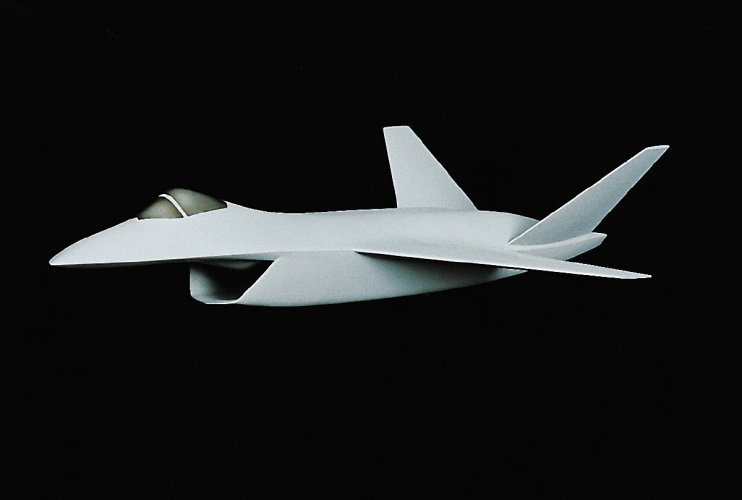
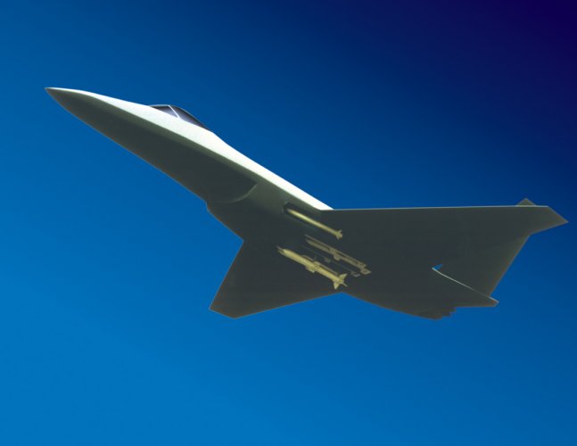
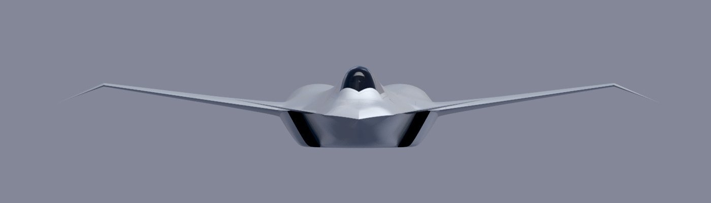
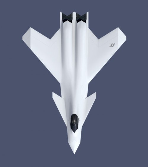
A few of the concepts Boeing explored in the past do show canards that are quite forward to the front of the aircraft.
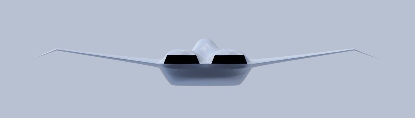
But at this point I'm not even sure that what we are seeing here are really canards. The pictures have been heavily "played" with, so my assessment might be completely inaccurate, but I don't see hinge lines for them: maybe they don't pivot as normal canards do and, instead, they just...flex?
Would they still be canards if that were the case? Or maybe they are fixed?
Only time will tell...
Maybe what they are hiding in those censored pictures they released, was a third dorsal inlet a la J-36 all along and I'll need to add that ¯\_(ツ)_/¯
More of the beak:
View attachment 765938

")