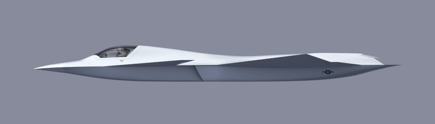
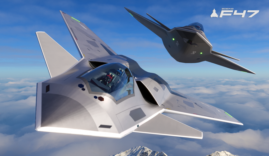
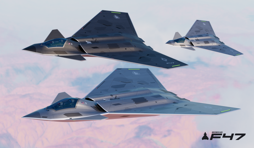
Well, as i said this is just quick notional edit for a TD (Tech. Demonstrator), an eyecandy, adding to the guessing fun, before the prototype gets revealed in a ceremony & we start getting documentaries on NGAD.
")
I did this after noticing the X-36, Bird of Prey, J-20, other delta-canards like Rafale, EF-2000, Gripen, Vigen, Draken, etc.
AFAIK, most of the individually thought 3D CAD models are similar. No artist has presented calculations of C.o.G., C.o.L. etc. Very few even mention the dimensions.
IDK if the C.o.L. shifts back with speed.
1 thing i know is for unstable jet the C.o.G. is little behind the C.o.L. & vice-versa for stable jet:
View attachment 766375
I read that modern fighter jets need to be designed unstable for agility & controlled by avionics computers.
So let's assume that C.o.L. will be litlle ahead of C.o.G.
IDK formula for C.o.L. but for a simple scalene triangle C.o.G. is on Centroid which is 2/3rd of length from forward tip & 1/3rd of height/width outward from base:
View attachment 766377
But finding C.o.G. of aircraft is complex bcoz the mid-fuselage has hollow ducts but not the aft fuselage with engines. The equipments & fuel tanks are smeared all over the airframe.
To make things little easy, the C.o.G. should be ahead of main/rear landing gear or the plane will tip over backwards.
So in the modified design, exchanging the wings & tail-stab positions, shifts the airframe Co.G. backward a lot.
> hence i didn't move the engine as it'll complicate things for me, shifting the C.o.G. back more.
> pushing the canard (tail-stab) little forward shifts the C.oG. & C.o.L. little forward to balance wing.
> removing rudder lightens rear fuselage & shifts the C.o.G. forward.
> adding chines to nose will move the C.o.G. little forward. It may also add to lift.
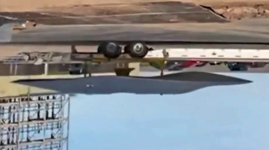
> if the MLG is also pushed back then it shifts C.oG. little back but also the fulcrum back, it should prevent the plane from tipping over back. I did this in the side & bottom views but didn't share them bcoz it is incomplete, imagining the forward fuselage area is complex. Intake area has to be maintained which affects nose shape. The following is the incomplete diagram with MLG shifted back:
View attachment 766390
Perhaps the canards should be shifted more forward & wing lengthened, leading edge sweep angle increased.
That's all my low IQ brain can think of. LOL!
I'll try a V2 of these diagrams.
But to translate this into a flyable jet's diagram will need a S/w which can input the density of structure, weight of components & will tell us the computed output of C.o.G. at least. IDK if 3D CAD S/w like Blender, Fusuion360, etc can do it.