xstatic3000
ACCESS: Confidential
- Joined
- 15 September 2008
- Messages
- 99
- Reaction score
- 43
These are just outstanding. Thank you so much for sharing your incredible work with us!

Thank you!If only the DoD hired someone as talented as you for their concept renderings

I believe that happened only for Dan Sharp's bookazine about the F.155T IIRC.Just out of curiosity have you ever attempted doing a series? Like all the proposals for a particular program?
Wonderful. So what's your usual approach to picking the next inspiration? Just whatever catch your eyes?I believe that happened only for Dan Sharp's bookazine about the F.155T IIRC.
I think I did model all the proposals submitted.
Yes, it's pretty much just that.Wonderful. So what's your usual approach to picking the next inspiration? Just whatever catch your eyes?
One more, just because it's so ugly it looks almost good...More please

No, it looks good, in a beefy way, and it looks different to the F-22/F-35 "standard look"One more, just because it's so ugly it looks almost good...
View attachment 725482
Second coming of A-7 Corsair III, this is the design Boeing should have gone with, it does not look that bad.One more, just because it's so ugly it looks almost good...
View attachment 725482
A pity Gloster didn't offer this to the RAF.
Beautiful Citrus
any more views??

Fancy doing some big wing Sea Harrier’s?I think I've now officially run out of ideas and materials for new projects...
A few interesting designs from DEFE 71/1139 Naval Staff Target 6464: Sea Harrier replacement:
All were to feature the Blue Vixen radar from the Sea Harrier FA.2, and the Zeus ECM system from the Harrier GR.5. They were to be fitted with either the Pegasus 19 or RB.532 engine offering a 15% or 30% increase in thrust respectively over the Pegasus Mk.104/5 used in the Sea Harrier FA.2 / Harrier GR.5.
- Shar 3A - Based on Sea Harrier FA.2 with larger wing (9.2 m)
- Shar 3B - Based on Sea Harrier FA.2 with even larger folding wing (11.9 m)
- P.1227 -Based on Harrier GR.5 with larger folding wing (11.9 m)
By the way any change of further views of Model 1074-0006? If you still have that modelThanks for your suggestions guys.
They all are in the pipeline, and will come in the next few weeks.
In the meantime I had already started on Flateric's proposals and here they are. I hope you'll like them.
Kind regards.
Well, I mean...isn't that just another Harrier?Fancy doing some big wing Sea Harrier’s?
Sure thing!By the way any change of further views of Model 1074-0006? If you still have that model


I am stupid.By the way any change of further views of Model 1074-0006? If you still have that model


Well this was lucky mistake, more Mach 6 research aircraft views are awesome too! Thanks!I am stupid.
I don't know why, but when you asked about the Model 1074-0006 my brain thought "ah, yes! The McDonnell Mach 6".
Apologies, here's the proper views you requested:
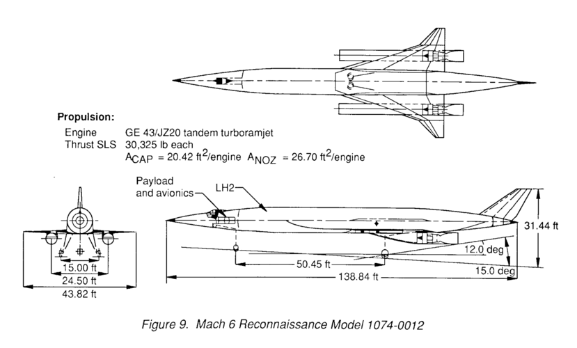
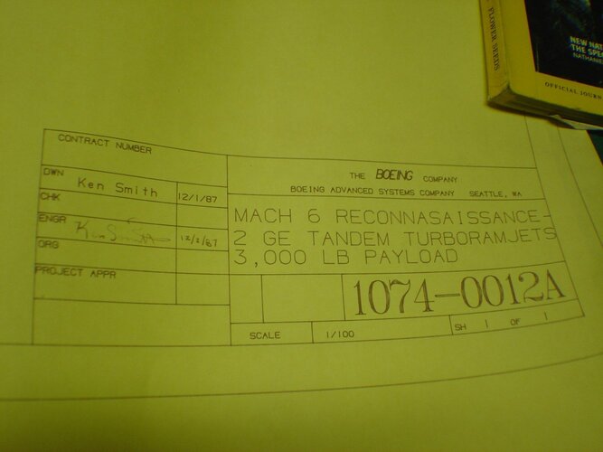
I'd love to, but...Now we also have the 1074-0012 to go along if you have the interest and time at some point...


...I'd love to, but...
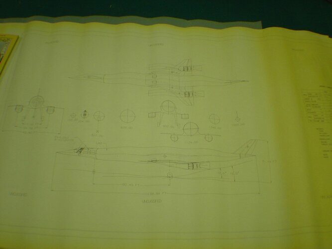
Like with many other projects that I'd really like to put into 3d, the available drawings are few and very unclear on the shapes depicted.
The drawings for 1074-0012 are one such example.
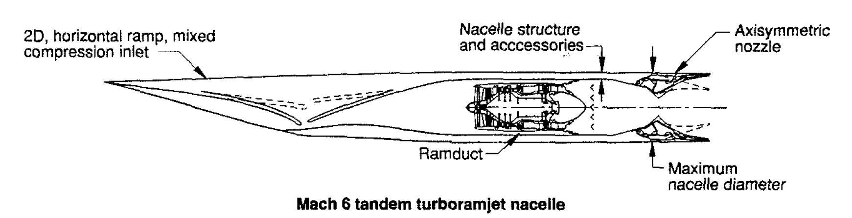
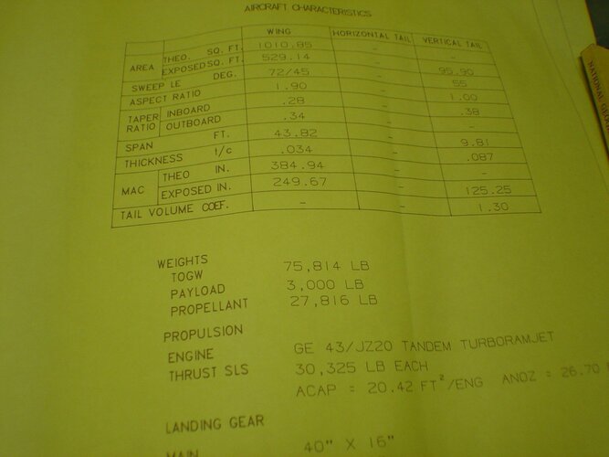
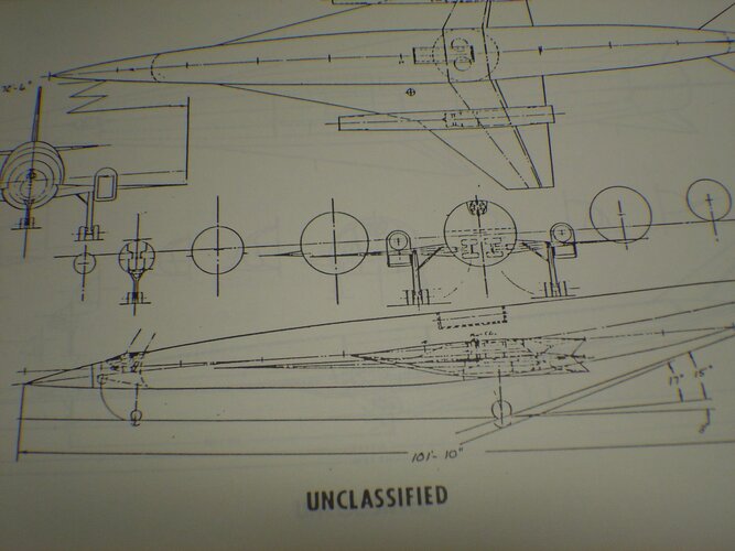
Yeah, agree, and this is something I too often struggle with. Though in this case the engine cutout from the report which flateric posted does provide some clues. If I was to model this I would probably use the separate engine drawing instead of the main three view as the basis for modeling the engine, the three view side shot might be missing part of the inlet for whatever reason.I'd love to, but...
Like with many other projects that I'd really like to put into 3d, the available drawings are few and very unclear on the shapes depicted.
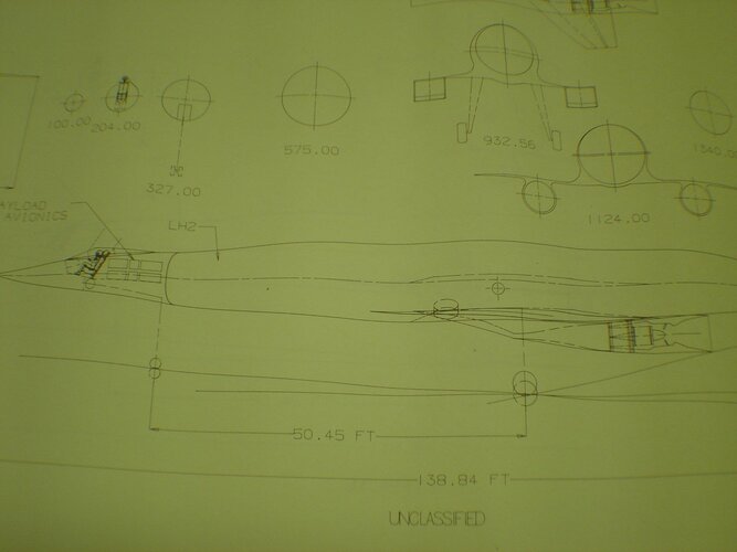
It's a bit more complicated than that unfortunately, because I'd still have to pick 1 out of 3 views to base my model on.Though in this case the engine cutout from the report which flateric posted does provide some clues. If I was to model this I would probably use the separate engine drawing instead of the main three view as the basis for modeling the engine, the three view side shot might be missing part of the inlet for whatever reason.


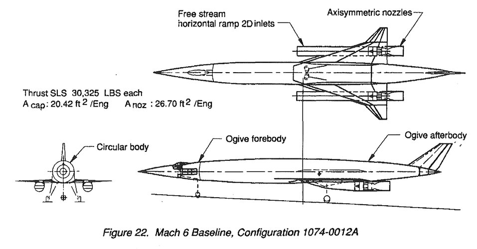
 (And of course if there is a more suitable three view of 1074-0019C available, a model of that would be great too!)
I think it's because the side view shows a fuselage cross section as well as whatever is behind it outside the fuselage contour, but not what's in front of it.Yeah, agree, and this is something I too often struggle with. Though in this case the engine cutout from the report which flateric posted does provide some clues. If I was to model this I would probably use the separate engine drawing instead of the main three view as the basis for modeling the engine, the three view side shot might be missing part of the inlet for whatever reason.
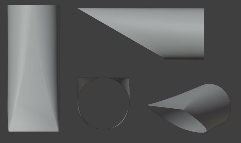
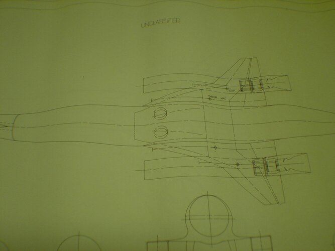
Yes, that's a possibility I also considered, but for the sake of simplicity didn't mention.Anyway since we got into this discussion attached is a quick sketch of how I would interpret the inlet so it mostly fits both top, front and side views. After all it is entirely possible for the shape to blend from edged to rounded over the length of the inlet (from 2D to 3D).
This one, on the other hand, shows even(And of course if there is a more suitable three view of 1074-0019C available, a model of that would be great too!)
 sections
seems so but ramp is positioned closer to nacelle C/L, not on topYes, I fully understand, and my original request wasn't meant to be taken too seriously, hence the wink emoji. I just thought it might be fun to collect the whole series
Anyway since we got into this discussion attached is a quick sketch of how I would interpret the inlet so it mostly fits both top, front and side views. After all it is entirely possible for the shape to blend from edged to rounded over the length of the inlet (from 2D to 3D).