Burnelli Projects

I found that the CB-300 designation of the CB-16 was the Chapman Burnelli 300. Paul Chapman, who bought a CB-16 from the Uppercu Burnelli works had a plan to launch and recover the CB-16 from his ocean liner the Leviathan. A model of the arresting net with a model aircraft (not the CB-16/CB-300) in the net is seen below. Note: Chapman attempted this feat with a Lt. C. Schilderhuaer, who could not find the SS Leviathan in the fog and returned to the airfield.
 

Attachments

  • Chapman Burnelli Leviathan.jpg
    Chapman Burnelli Leviathan.jpg
    898.5 KB · Views: 280
Last edited:
hesham said:
What was this ?.
That looks like a model of a variant of the Burnelli CBY-3 Loadmaster.
cby3-2.jpg
 
That is the CC&F built CBY-3. It has the registration of the sole flying model of this aircraft.
 
Last edited by a moderator:
That is the CC&F built CBY-3- it has the registration of the sole flying example.
 
Does anyone have performance estimates for either the X-BAB-1 or the A-1?
 
Regarding the Burnelli mail experiment:

"Ship-to-Shore Pick-up: The SS Leviathan
Chapman [Adams’ financial backer], hoping to establish the world’s first permanent ship-to-shore service, financed a demonstration on the SS Leviathan, flagship of the United States Lines fleet. The same ship was used in a similar demonstration on July 31, 1927, when the first ship-to-shore flight was made by Clarence D. Chamberlin. Chapman treated Adams royally, providing him not only with intensive public relations support, but also with accommodations for his staff. Doc’s serviceable but unwieldy trap was increased from a width of twenty-one feet to thirty-five feet and placed 100 feet above the water line at the ship’s stern. The first pick-up attempt was scheduled for June 6, 1929. Unfortunately, the Burnelli monoplane which was to be used, crashed at Keyport, New Jersey, on June 5. Adams hurriedly installed his equipment in a Loening amphibian. At 2:00 PM on June 6, Lieutenant Commander George R. Pond took off from Newark Municipal Airport, stopped at Roosevelt Field for a wireless test, then flew to New Bedford for refueling. Leviathan stood ready off Nantucket Lightship, but the Loening was struck by lightning. Pond aborted the flight. The next morning, Pond made another attempt, this time with Adams who was armed with a camera. Adams hung dangerously out of the hole made for the pick-up equipment, a position he assumed would be conducive for a good photo. Pond encouraged him back into the plane. Pond aborted this attempt as well. Dense fog obscured the ship. Doc arranged still another attempt, this time with two planes, a Fairchild monoplane to make the pick-up, and the Loening to carry a bevy of photographers. At 3:30p.m., June 12, the Leviathan proceeded in an easterly direction. Adams was on board. Two hours later, Pond, toting a forty-pound bag of mail, climbed into the Fairchild. Both planes took off from Keyport, New Jersey, and reached the liner around 6:50 p.m. Pond circled, swooped down, dropped the bag of mail into the trap, and picked up the ship’s mail. They landed at Newark about one hour later. When he arrived back in the United States, Adams was confident that he would receive a permanent contract, but Chapman’s public relations efforts had backfired. The Post Office Department canceled Chapman’s contract, charging that his line had used the contract to sell stock in the company, stock that had risen considerably in price during the demonstrations." (p. 23) https://dspace.njstatelib.org/xmlui...882/205njphfeb2017.pdf?sequence=1&isAllowed=y

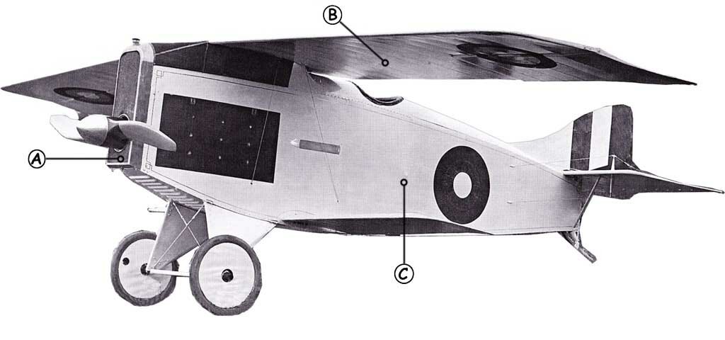
I'm curious what the Burnelli monoplane (that crashed June 5, 1929) was the CB-16 (the Paul W. Chapman aircraft constructed at Keyport, NJ), which flew initially 8 January 1929.
 

Attachments

  • Burnelli_CB-16_left_side_Aero_Digest_February_1929.jpg
    Burnelli_CB-16_left_side_Aero_Digest_February_1929.jpg
    94.3 KB · Views: 125
Last edited:
The CB-16 was the crashed aircraft according to the document below:

"Its career ended in 1929, after Mr. Chapman loaned the aircraft for a demonstration of the Cabot Adams aerial recovery device, designed for picking up airmail from the S.S. Leviathan, 300 miles at sea. During airfield tests, piloted by Commander George Pond, USN, maintenance work on the control system resulted in the crossing of the aileron drive cables. On takeoff from the Keyport, N.J., plant, the plane assumed a near-vertical position and crashed. This, to an amazing extent, demonstrated the inherent safety of the design. The pilot and his assistant were not injured. The location of the engines forward of the pilots, and the stronger fuselage section, saved their lives. It is difficult to imagine a more severe ground contact from a more awkward piloting position."
 

Attachments

  • 196310-1928 Burnelli CB-16 Executive Plane.pdf
    3 MB · Views: 34
Last edited:
"Unfortunately Vincent Burnelli’s work at Continental is most noted for his involvement with Dr. William Whitney Christmas, and the notorious Christmas Bullet Aircraft. The Christmas Bullet was a doomed vehicle with irrational construction techniques of Dr. Christmas design. Two of the vehicles were built and both vehicles crashed on their maiden flights, killing their test pilots. Vincent Burnelli who was an unwilling participant in the Christmas Bullet project, walked away from the Continental Aircraft Company as his final act in a failed attempt to stop the flight test of the aircraft. Unfortunately the crash of the Christmas Bullet was not attributed to Dr. Christmas but was directed at Vincent Burnelli and others at Continental." The Contributions of Vincent Justus Burnelli - Richard M. Wood AIAA 2003-0292

"Meanwhile, the nearly-bankrupt Continental Aircraft Company of Amityville, Long Island was enlisted to build the airframe to Dr. Christmas' specifications. Eventually Senator Wadsworth convinced the Army to supply an engine, but they did so with the caveat that they allow the Army to see and test the airplane before it was flown. The 'specifications' that Dr. Christmas had in mind (he was afraid to commit them to paper) were so bizarre that even the Continental people- who were desperate for business - thought twice. Simply put, he was breaking every rule in the book. His overriding theory of aircraft design was that struts and bracing should be eliminated, and that the wings should be so flexible that they could literally flap like a bird's! To top this unorthodoxy, Dr.Christmas insisted on constructing his airplane of steel and hardwood." http://www.fiddlersgreen.net/models/aircraft/Christmas-Bullet.html
 

Attachments

  • Christmas-Bullet-Callout.jpg
    Christmas-Bullet-Callout.jpg
    39.6 KB · Views: 167
Burnelli KB-3T

(Janes All the World Aircraft 1919)
The Continental Aircraft Corporation's new training tractor KB-3T recently tested at Amityville, has come up to all expectations of the designer Vincent J.Buranelli. The short "over-all" length of this machine, 23 feet 4 inches, is noteworthly and characteristic of Continental machines.
Mr. Buranelli's chief object in designing the KB-3T was to produce a training machine that could be cheaply constructed. This has been accomplished by an extensive use of one-piece standartized fittings. A very complete list of neasurements and weights are given which should prove useful in checking up with other machines.

General Specifications.

Span upper plane 40 ft. 3in.
Span lower plane 34 ft.
Chord both planes 5 ft. 6 In.
Gap 5 ft. 4 in.
Stagger 6 in.
Length over all 23 ft. 4 in
Height 9 ft. 3 in.
Net weight 1.340 lb.
Useful load 540 lb.
Gross weight 1,880 lb.
Motor. Curtiss OX 100 h.p.
Speed range 45-75 m.p.h.
Climb in ten minutes 3,200 ft.

Weights.
Upper planes 118 lb.
Lower planes 102 lb.
Struts 30 lb.
Wires and turnbuckles 20 lb.
Fittings and bolts 18 1b.
Total 288 1b.

Fuselage 310 lb.
Seats upholstered 12 lb.
Stick controls and mountings 17 lb.
Dash with instruments 13 lb.
Total 352 lb.

Ailerons 24 lb
Elevators 16 lb.
Rudder 10 1b.
Vertical stabilizer 3 lb.
Horizontal stabilizer 19 lb.
Control cables 16 lb.
Total 88lb.

Motor complete 390 lb.
Propeller 22 lb.
Radiator and piping 53 lb.
Gas tank and gauges 22 lb
Exhaust pipe 16 lb.
Total 503 1b.

Landing chassis and incidentals = 109 lb.

Planes.
The wing curve is Eiffel 38. The planes are set with an angle of incidence of 21 degrees. Top and bottom are the same The tips of planes are slightly rounded as is in general use on Continental machines. Then is no sweepback, but a dihedral of 1 degree and a stagger of 6 in. The upper planes are made in two main sections with a three-foot panel over the body. The lower plane is in two sections and attaching to the body. ' Wing beams are of " I" section and made of Douglas fir. The overhang is braced by a steel strut made of | in. seamless tubing with a fairing of spruce
The struts are of streamline section, the maximum 3 3/4 in. x 1 1/2 in. occurring at the centre, and tapering in proportion to each end where it sets into a special strut socket. Flying cables are double 5/32, in. in inner panel, 1/8 in. outer panel, landing wires are single of the same sizes. Double drift and single tracing wires are used. All control wires are internal.
Ailerons on top plane only, and are 11 ft. x 1 ft. 6 in. Where ailerons are attached, a bevel on the aileron permits the surface to be moved without a space occurring between aileron and wing.
R. A. F. stitching is employed in attaching the fabric to the ribs. To finish four coats of " dope " and two coats of Valspar are used. A factor of safety of 7 is employed. The lift to drag ratio is 12.
 

Attachments

  • Continental_KB3T.jpg
    Continental_KB3T.jpg
    65.3 KB · Views: 184
  • Aerial Age Weekly KB3T.pdf
    224.8 KB · Views: 11
Last edited:
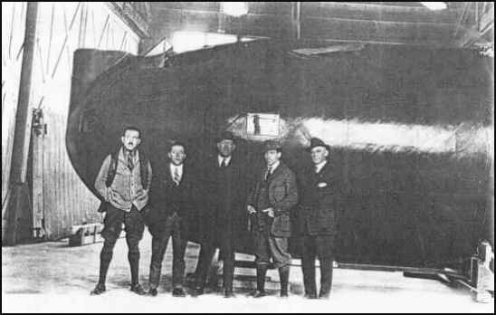
As an aside on the Burnelli projects, Vincent Burnelli was supposedly an engineer on the Barling BNL-1 Bomber in 1922. His friend, John Carisi, who helped him build his first airplane and who worked with him on the Lawson Airliner, was the superintendent on the Barling project. Vincent worked at Wittemnan Aircraft in Teterboro, NJ 1922-1923. First picture, Burnelli second from left, and in the second picture he is the fourth from the left.
 

Attachments

  • schoberbarcrew2.jpg
    schoberbarcrew2.jpg
    22.4 KB · Views: 113
  • schoberbarcrew1.jpg
    schoberbarcrew1.jpg
    17.9 KB · Views: 149
Here is some Burnelli designs with Canadian CCF,also there were the CBY-3
and also the CBY-4 with "Loadmaster 4" Projects.
 

Attachments

  • Loadmaster 4.jpg
    Loadmaster 4.jpg
    141.4 KB · Views: 138
  • 81.jpg
    81.jpg
    151.4 KB · Views: 133
  • 80.jpg
    80.jpg
    155.1 KB · Views: 131
  • 79.jpg
    79.jpg
    140.5 KB · Views: 129
  • 78.jpg
    78.jpg
    138.4 KB · Views: 128
  • 77.jpg
    77.jpg
    129.3 KB · Views: 126
  • 76.jpg
    76.jpg
    148 KB · Views: 127
  • 75.jpg
    75.jpg
    143.6 KB · Views: 131
  • 74.jpg
    74.jpg
    126.6 KB · Views: 133
  • 73.jpg
    73.jpg
    146.8 KB · Views: 127
  • 72.jpg
    72.jpg
    112.8 KB · Views: 118
  • 71.jpg
    71.jpg
    151.8 KB · Views: 116
  • 70.jpg
    70.jpg
    148.1 KB · Views: 121
Excellent Hesham!
Can you put a designation on these designs?

My dear Lark,sorry,

they only said;

A variety of CBY-3 iterations ( at least a dozen pictured below) as investigated by Canadian Car and Foundry and drawn by their engineer, V.R. Wallingford, including some which incorporated the cockpit into the engine nacelle,. It seems that while Burnelli provided the main "lifting body" design idea, he largely left the details to CC&F to work out what would consitute an airworthy aircraft. photos courtesty of Canadian Air and Space Museum, Ingenium, Fred Short Fonds CCF CBY-3 file.
 
Here is some Burnelli designs with Canadian CCF,also there were the CBY-3
and also the CBY-4 with "Loadmaster 4" Projects.

Story of the CB-34
A colourful magazine cover on a 1939 edition of Model Airplane News excitedly depicted a futuristic looking bomber speeding over a sinking ship, an artist’s rendition of what he perceived a new anticipated Burnelli aircraft would look like, and which was identified as the CB-34 bomber. As it turned out, the artist’s description and rendering of the aircraft was close, but a little off the mark, since it’s Canadian manufacturer had other plans for the design.

The CC&F had for years specialized in railroad car manufacture, but sometime in the mid 30’s, management had astutely decided that there was good business to be had by expanding into the aircraft manufacturing business, as the promise of air transport’s advantages over rail service became more apparent especially across Canada’s vast borders. One candidate that caught their attention was one of Burnellis radical “lifting body” aircraft, the UB-14. Burnelli had had some success with his UB-14, displaying it in Belgium, the Netherlands and the UK where aircraft manufacturer Cunliffe-Owens had even built one under licence with the intent to build more. The original was later sold to Nicaraguan airline, TACA, and when Burnelli’s company subsequently went bankrupt, CC&F came to his rescue, and in the process, acquired his patents and rights to build the UB-14. It seems the purchase was a godsend for Burnelli, and soon he was working closely with CC&F designing new aircraft that incorporated his lifting body design.
At their Fort Williams plant, management announced plans to soon begin production of the UB-14 while back in Montreal, ambitious efforts were underway to develop an even larger, more ambitious version, twice as wide as the UB-14, called the CB-34 which would be built in Fort Williams as well. The mock-up included the full fuselage and right wing built of wood at the company’s Cartierville factory, but photos and correspondence reveal that the CB-34 was intended to be a commercial transport if built by its Canadian financiers, rather than a bomber (although other plans for a future bomber were also investigated). It is likely the “B” in the classification stood for “Burnelli” rather than “bomber” and it’s builders more intent on capturing the burgeoning air transport opportunity across Canada than competing against larger American manufacturers already engaged in bomber construction.
Unfortunately for CC&F and Burnelli, the Department of Transport was both skeptical about the viability of a transport plane to be made in Canada and resistant to accepting a radical new design despite already having been proven and accepted by the UK civil aviation authorities. In fact, when CC&F’s general manager and vice president, L.A. Peto, wrote to the Minister of Transport to ask for his assistance in approving technical drawings as they were finished, the controller of Civil Aviation (who reported to the Minister) noted “Let sleeping dogs lie” on a copy of the letter shared internally as though to suggest administration staff should provide as little assistance as possible . Another civil aviation inspector (who’d visited the factory to inspect a full-scale mock-up), noted that while the company’s claims of performance seemed legitimate and not exaggerated, the “problem of placing it in commercial operation was something else again”. Below the comment, the Civil Aviation Controller initialed his name with the comment “I agree” effectively signalling that the Department of Transport had no intention of supporting CC&F’s ambitious endeavour.
What followed, was a series of roadblocks and endless requests for additional information from the Department of Transport, essentially delaying any progress on the construction of a flying aircraft. Ultimately, Canada’s entry into the war would bring a number of contracts to CC&F to build American-designed aircraft such as the Hawker Hurricane, and further development of the CB-34 was shelved as these new priorities occupied most of the company’s resources. Nonetheless. as the war later drew to a close, a scaled down, twin-engine version of the CB-34, called the CBY-3 would finally result in a finished aircraft which the determined CC&F staff believed to be a sound overall design and that offered numerous advantages over conventional aircraft.
These photos of the CB-34 mock-up taken by the Department of Transport inspector may be the only existing images of the CB-34, tucked away in the National Archives for over 80 years and only revealed recently after declassification and a Freedom of Information request.


Attachments

  • 500.jpg
    500.jpg
    105.2 KB · Views: 114
  • 600.jpg
    600.jpg
    64.8 KB · Views: 110
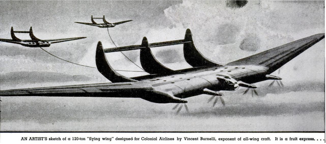
From Popular Mechanics;


Here is a clearer and bigger view,from Rotarian 1945/1.
 

Attachments

  • 900.png
    900.png
    1.4 MB · Views: 99
From this book,

please notice Canadian Car MB.2.
 

Attachments

  • 27.png
    27.png
    358.3 KB · Views: 73
  • 26.png
    26.png
    531.7 KB · Views: 77
  • 17.png
    17.png
    1.5 MB · Views: 86
  • 16.png
    16.png
    60.2 KB · Views: 82
  • 15.png
    15.png
    68 KB · Views: 80
  • 13.png
    13.png
    1.1 MB · Views: 81
  • 12.png
    12.png
    768.8 KB · Views: 74
  • 11.png
    11.png
    671.9 KB · Views: 68
  • 10.png
    10.png
    5.1 MB · Views: 73
  • 0.png
    0.png
    910.1 KB · Views: 71
Burnelli B-2000B

Are any dimensions - i.e. span and length - available for this aircraft?

AlanG
 
Orion,

Thanks very much for the data on the B-2000B.

One question, though. The 3-views are dated "circa 42". By 1942 the B-36 contract had been issued months previously, IIRC, and work on the prototype had already begun.

Yes? No?

AlanG
 
Well, it is a "Burnelli Project" ... :)
Apr 10, 2024
I've been working on this 37" Burnelli twin since early February '24, and I'm pleased with the progress.
There were numerous concept sketches for this design from the mid to late '40s, so I chose one with the cockpit over the left side nacelle, which gives me a wider fuselage for more prop diameter, and a clear airflow to the wide lifting body. Seems ideal for free-flight rubber. I hope to have her ready for the trim field at Wawayanda by early June.

 
Here's the latest on that Burnelli Project in balsa and tissue, covering/painting and trimming for flight,

May 28, 2024
This film shows a few of the stages of building the 37" free-flight rubber-powered Burnelli Transport concept aircraft from 1947. It then focuses on the methodical, eleven flights of the model's first trim session, ending in a beautiful soaring flight in Wawayanda, NY. Filmed by Tom Hallman on 5.25.24 with a Canon PowerShot SX20, and iPhones 11 & 14Pro. Music via the talented musicians at ArtList.io, who breathe life into my films.

First day notes with the Burnelli:

Started at 200 winds…then methodically worked up the ladder by
100 and then 150-200 turns with each new flight. Max turns in the 1900-2000 range.
Used the same motors (2 loops x 3/16" x 40") that singularly power the 27" Seafire & 28" Cauldron. Both use a 10" EB white prop...compared to the 8-7/8" props for the Burnelli.

The quick fix was more downthrust (twice), nose weight, right rudder via
1/32" thick gurney flap, and a touch of gurney on the lower left to help hold that right
turn…although I might remove it or adjust the location after seeing what the increased torque did to the initial power burst. I’d rather see the bird climb a bit flatter thru the first circle. With 500+ turns to go, I’ll need to keep an eye on the torque effect.

Cracked a bamboo skewer prop spar...twice, when it outflew the field, landing on the hardened dirt of the neighboring crop section. I’ll resolve these issues for the future. The 1/16” dia. toothpick rivets that I use are great for holding the blades in place, but I should not have had the one closest to the hub, as it created a weak spot in a heavy stress / leverage area.

I thought I’d be OK with shrink wrap tubing for the canopy but the hours of hot, direct
sun had other intentions, so that’ll be replaced with the good stuff, PETG plastic via the vacuformer.

I have growing concern for the lack of a DT on this model. But yes, a fantastic first day out with this unusual design.

"DT" is dethermalizer. See: https://www.modelaviation.com/Using-Dethermalizers

 
Last edited:
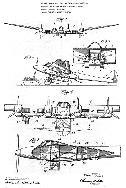
In a patent entitled "Military Aircraft", dated 03.15.1943 and registered in the name of the Canadian Car and Foundry Company under number 425934 dated 03.06.1945, Burnelli exhibits a large composite military aircraft carrying a droppable load under the shape of an armored tank, a watercraft, an aerial torpedo or any other device as well as a large number of paratroopers dropped conveniently from the plane. The airplane is thus able to transport a tank to enemy terrain and to leave it there, without alighting. As for the aerial torpedo Once launched, it must be controlled in flight towards the target. For this purpose, a vertically sliding turret is occupied by an operator who, using a radio beam and a command, directs the torpedo towards the target which is within the operator's vision.
 

Attachments

  • B.jpg
    B.jpg
    993 KB · Views: 53
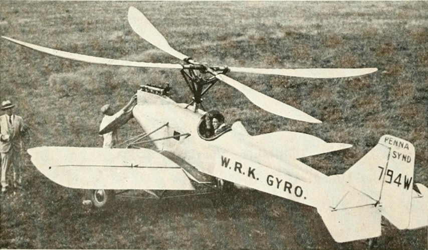
Burnelli, while based in Keyport, NJ, working from leased floorspace in the Aeromarine Plane and Motor Company plant developing the Paul Chapman CB-16, Vincent Burnelli partnered with E. Burk Wilford to design and build the license-to-build gyroplane patented by German designers Walter Rieseler and Walter Kreisler. This gyroplane was entered into the 1927 Guggenheim Safe Airplane Contest. Below is the Wilford gyroplane.
 

Attachments

  • 1717089951052.png
    1717089951052.png
    856.5 KB · Views: 44
Last edited:
Full size or flying model, test flights have hazards:

And doesn't it look good in the air!

Jun 5, 2024
This film shows the second trim session of the 37" free-flight rubber-powered Burnelli Transport concept aircraft from 1947, flown in Wawayanda, NY. Filmed by Tom Hallman on 6.3.24 with a Canon PowerShot SX20, and iPhones 11 & 14Pro. Fantastic photos taken by Peter Kaiteris with a Nikon D3400 70-300mm. Music via the talented musicians at ArtList.io, who breathe life into my films.

Trim session notes:

The cracked right prop spar was replaced, along with the thrust plates, which were at the edge of holding their position beneath the flathead screws. This led to a slight shift in the thrust, which was adjusted at the field after the morning trim session. I continued preferring the right pattern at launch, through the use of 1/32" thick gurney flaps on the TE & right rudder.

But the tilt of the wing was too much, which prevented her from climbing at the power burst, so on the final golden hour flight, I trimmed the gurney flaps a bit, which helped flatten the initial power portion, giving her a wider circle and higher climb. I also added more nose ballast, which helped keep the nose down during the power portion, and did not seem to hinder the glide.

Max winds might not be as much as I had hoped, but so far, she's up to 1740. I'd like to get a bit higher, closer to 1900. She still has a slight stall during some of the glide portions, which will get more attention in future sessions.

 
From my database:

RB-419270Transport aircraft project with two Atlantic engines; listed in several period publications.
RBL-6nd0No data. Project listed in some period publications.

I do not know what/who the "L" stood for, nor what those "Atlantic" engines were supposed to be. Has anyone encountered them before?
 
From Feb 18, 1926 Automotive Industries Magazine

Remington-Burnelli RBL-6
Single engine, Tractor monoplane, 8-seat passenger/freight, land-based aircraft.
Specifications: 400 hp, V12 Liberty, water-cooled. 36 ft length, 8.5 ft height, 54 ft wingspan. Weight empty 4600 lbs, Weight gross 7400 ibs, useful load 2800 lbs. 120 mph max speed, 102 mph cruise at 10,000 ft., landing speed 58 mph. Wing chord average 9 ft 3 in., 640 sq ft wing area. Tail surface area 68 sq ft, vertical tail surface area 36 sq ft. Sweepback angle 0 deg.
 
Last edited:

Please donate to support the forum.

Back
Top Bottom