You are using an out of date browser. It may not display this or other websites correctly.
You should upgrade or use an alternative browser.
You should upgrade or use an alternative browser.
Westland Whirlwind Variants and Projects
- Thread starter GTX
- Start date
Hi JFC,
Thanks a lot, that's a very interesting diagram!
It's worth noting that the values used for range calculation assume a consumption of about 94 imperial gallons per hour for "action" and patrolling at 310 mph, while the Pilot's Notes for the type state it consumes 115 imperial gallons per hour at maximum cruise power (rich), and 151 imperial gallons per hour at "all-out level", which probably would be the preferred power setting for combat.
The Pilot's Notes might include a safety margin in their consumption figures, but I guess you'd want to have that same safety margin in your range and endurance calculations when assessing the tactical suitability of the type ...
Regards,
Henning (HoHun)
I have been meaning to post this for a while. This is the proposed fuel layout for the Whirlwind Mk.II which as the document makes clear was substantially improved over the Mk.I. I would also note that this is also not the final configuration, that had a further revised nose with the 25 gallon tank replaced with a 30 gallon tank so the total in that case would have been 199 gallons.
Thanks a lot, that's a very interesting diagram!
It's worth noting that the values used for range calculation assume a consumption of about 94 imperial gallons per hour for "action" and patrolling at 310 mph, while the Pilot's Notes for the type state it consumes 115 imperial gallons per hour at maximum cruise power (rich), and 151 imperial gallons per hour at "all-out level", which probably would be the preferred power setting for combat.
The Pilot's Notes might include a safety margin in their consumption figures, but I guess you'd want to have that same safety margin in your range and endurance calculations when assessing the tactical suitability of the type ...
Regards,
Henning (HoHun)
Hi again,
I just noticed that there's a new article up on the same topic available on the (re-launched, it seems) Whirlwind project page:

 www.whirlwindfp.org
It seems to be a more conventional explanation this time around, though I'm not entirely sure of this as the use of the term "hunting" and the mention of an "intermittently windmilling" propeller sound a bit odd to me:
However, there's a footnote reference though the website shows no footnote reference, so maybe that's just a poorly worded summary of something that actually makes more sense.
There's also an interesting visitor comment below the article:
That's a bit like what Stanley Hooker of Rolls-Royce also diagnosed for the Spitfire intake, I believe. I also read that Jiro Horikoshi found a similar intake problem as the cause of the A6M3's disappointing performance at altitude, which was cured with a redesigned intake of increased size.
Regards,
Henning (HoHun)
So, I'd say this guy behind DAWA has identified an interesting aspect of Whirlwind performance, and maybe one where the propeller the series-production Whirlwinds received did in fact harm the type's performance, but my preliminary impression is that the detailed reasons for this are probably not reflected perfectly accurately on the DAWA page.
I just noticed that there's a new article up on the same topic available on the (re-launched, it seems) Whirlwind project page:

When the Wind Won't Whirl - or the real reason the Whirlwind suffered at height. - WFP
The Whirlwind was said to have been let down by its engines. This never added up to the WFP's Matt Bearman and in an article originally published in The Aviation Historian quarterly Matt unearths some surprising facts,
 www.whirlwindfp.org
It seems to be a more conventional explanation this time around, though I'm not entirely sure of this as the use of the term "hunting" and the mention of an "intermittently windmilling" propeller sound a bit odd to me:
Furthermore, wildly varying dynamic pressures would be passed into the ram-air intakes, which sit immediately behind the blades.8 The system becomes what a physicist would call “chaotic”. The intermittently windmilling prop produces fluctuating boost pressures on top of reduced r.p.m.
However, there's a footnote reference though the website shows no footnote reference, so maybe that's just a poorly worded summary of something that actually makes more sense.
There's also an interesting visitor comment below the article:
Richard Turner
10/11/2023 04:08 PM
A recent exchange of letters published in "Aeroplane" magazine also referred to a whirlwind that was returned to Rolls Royce in an attempt to improve the power of the peregrine engines. Rolls Royce found that the air intakes to the engines were too small and followed a convoluted path , they modified the aircraft sent to them and gained a considerable increase in power. Apparently the modifications were dismissed by Westland because Rolls Royce were just car engine people and knew nothing about aeroplane construction.
That's a bit like what Stanley Hooker of Rolls-Royce also diagnosed for the Spitfire intake, I believe. I also read that Jiro Horikoshi found a similar intake problem as the cause of the A6M3's disappointing performance at altitude, which was cured with a redesigned intake of increased size.
Regards,
Henning (HoHun)
_Del_
I really should change my personal text... Or not.
- Joined
- 4 January 2012
- Messages
- 1,315
- Reaction score
- 1,808
Usually used in the context of a transmission. I had an old Chevy with automatic transmission that would "hunt" right about 35mph. Couldn't decide which gear it wanted, and would cycle between them seemingly endlessly until you added speed or slowed to make the decision easier on it.It seems to be a more conventional explanation this time around, though I'm not entirely sure of this as the use of the term "hunting" and the mention of an "intermittently windmilling" propeller sound a bit odd to me:
Here he's talking about the constant-speed unit on a variable-pitch prop. When you get drag on the props, the shaft speed starts to slow because drag increases torque. A governor will tell the prop pitch control unit to get finer to lower the drag so the rpm does not drop.
So after a quick scan of the section, I'd summarize it by saying, they were getting into a drag regime it (the CSU) wasn't designed for. The author doesn't do a good job of explaining how a CSU works, and might be conflating a few things in the section (he mentions shockwaves across the prop surface blanking it, severely affecting thrust negatively, but that doesn't have much to do with the CSU -- just the drag).
Drag increases as a square to velocity. Here we seem to have found a transonic regime where that CSU "hunts".
The CSU can usually be set to different settings, trading RPM for efficiency. But within some varience, it is given a best rpm for the engine health, and it tries to keep it.
The way it can do that is by fining the prop or increasing the bite to keep the shaft at a constant speed. More drag means more torque, which will slow the shaft speed. Less drag, less torque, and the shaft can spin more freely. There is a governor wants the shaft to stay at constant speed. Changing the bite is essentially how it is done.
Here the PCU is taking the blade to minimums, hence windmilling -- ie, not creating thrust, flat to the incoming flow -- to keep the governor happy with the shaft speed -- because transonic flow is creating too much drag on the prop. Less bite, less drag says the PCU, and it takes it all the way to flat. If it goes flat, no thrust is produced.
No thrust, slower speed, less drag, results in a faster shaft. Well, the CSU quickly says, hey, too much shaft speed and the PCU changes the pitch for more bite.
So the CSU system is caught in a cycle "hunting" for the appropriate blade pitch for that flight regime and RPM setting. Sometimes getting no thrust (intermittent windmilling), sometimes getting small bite which is low thrust. Neither situation good for high-speed flight.
TL;DR -- Basically too much drag at high speed increasing torque at whatever specific velocity to hold the RPM they designed the CSU to hold in the highest healthy RPM setting.
Last edited:
Hi Del,
Well, I mostly agree with your description, but the act of the aircraft slowing down is comparatively slow while the pitch change is quite rapid, so I don't think that the cycle you describe would appropriately be described as "hunting", and with the engine running at full speed the entire time, there wouldn't be any boost pressure fluctations either.
Considering that there's often some kind of hysteresis effect to compressiblity phenomenons, maybe that could induce actual hunting? The propeller speeds up, increases pitch, the critical Mach number drops, drag increases in a leap, the propeller slows down, drag decreases but stays high, propeller decreases pitch and slows down further, suddenly angle of attack decreases critical Mach number below the lower hysteresis threshold, drag decreases in a leap, propeller speeds up, cycle repeats.
Problem with that is that's not going to be the entire propeller that undergoes the sudden drag rise, as local angle of attack and Mach number are different everywhere along the radius. And if the process is more gradual, the leap is averaged out, so I'm skeptical it could happen like that in practice. (And no boost pressure fluctuations with my explanation, either.)
What do you think?
Regards,
Henning (HoHun)
Less bite, less drag says the PCU, and it takes it all the way to flat. If it goes flat, no thrust is produced.
No thrust, slower speed, less drag, results in a faster shaft.
Well, I mostly agree with your description, but the act of the aircraft slowing down is comparatively slow while the pitch change is quite rapid, so I don't think that the cycle you describe would appropriately be described as "hunting", and with the engine running at full speed the entire time, there wouldn't be any boost pressure fluctations either.
Considering that there's often some kind of hysteresis effect to compressiblity phenomenons, maybe that could induce actual hunting? The propeller speeds up, increases pitch, the critical Mach number drops, drag increases in a leap, the propeller slows down, drag decreases but stays high, propeller decreases pitch and slows down further, suddenly angle of attack decreases critical Mach number below the lower hysteresis threshold, drag decreases in a leap, propeller speeds up, cycle repeats.
Problem with that is that's not going to be the entire propeller that undergoes the sudden drag rise, as local angle of attack and Mach number are different everywhere along the radius. And if the process is more gradual, the leap is averaged out, so I'm skeptical it could happen like that in practice. (And no boost pressure fluctuations with my explanation, either.)
What do you think?
Regards,
Henning (HoHun)
_Del_
I really should change my personal text... Or not.
- Joined
- 4 January 2012
- Messages
- 1,315
- Reaction score
- 1,808
Drag is going to change instantaneously as the bite changes across the entire prop because the bite/thrust/"lift"(if you will) creates it's own drag.Well, I mostly agree with your description, but the act of the aircraft slowing down is comparatively slow while the pitch change is quite rapid, so I don't think that the cycle you describe would appropriately be described as "hunting", and with the engine running at full speed the entire time, there wouldn't be any boost pressure fluctations either
Wherever the flow is supersonic locally, you'll see a massive change in the drag. And that change can be quite sudden. The whole flow does not need to be supersonic, just small areas of the local flow.
It will onset at the tips because the tip has the fastest rotational velocity (and there is small spanwise flow, like a wing). That's why you see thin, swept tips these days on high performance props.
Shockwaves, sudden significant drag, sudden significant less thrust. Slightly lower speed, no shockwaves, much more thrust, much less drag.
Yes, but also the tip has the fastest rotational speed. If the propeller tip reaches the critical mach number for it's airfoil, massive drag, massive thrust loss with the shockwave. Not sure how the rest of the slower prop evens that out. And we seem to be in an area of performance where the critical number is creeping up the span of the blades. The main airfoil is curved less aggressively across the middle. If you get supersonic flow across that, you could have a large section affected fairly rapidlyProblem with that is that's not going to be the entire propeller that undergoes the sudden drag rise, as local angle of attack and Mach number are different everywhere along the radius
I have no idea about the boost pressure fluctuations he talks about. Could there have been shockwaves impinging on the intake from the props? Shockwaves with sudden onset and then disappearing as the PCU dances trying to keep the governor happy? Would definitely affect pressure through the inlet.
- Joined
- 19 October 2012
- Messages
- 1,980
- Reaction score
- 1,931
Hi,
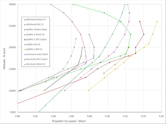
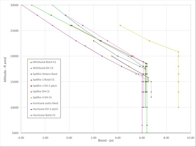
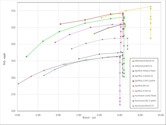
Quite interesting. With regard to the interpretation, it's a bit difficult to tell Mach-related effects apart from power-related aspects. The latter of course mostly consist of boost pressure dropping off above full throttle height, but at least for the fixed-pitch propellers, RPM would probably also vary with altitude.
Would it be possible to add this to the diagram?
In any case, it looks like the Rotol was operating at the lower end of the range, compared to the Hurricane and Spitfire.
Where's the Whirlwind data from? Usually, all the good stuff is on Mike William's wwiiperformance.com, but it looks like he hasn't covered the Whirlwind
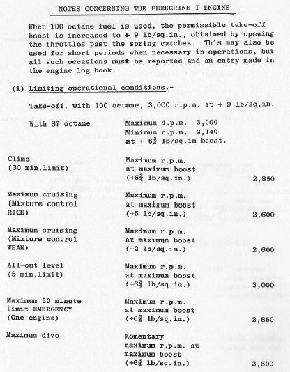
From the Pilot's Notes for the type, it seems that the "All-out level" rating was 3000 rpm, +5 3/4 lbs/sqin [though 5 and 6 look almost the same on the poor scan I have, and there's another, more general limit statement that I'd read as "+6 3/4 lbs/sqin"], but the Pilot's Notes also state that with 100 octane fuel, it was permissible to use up to 3000 rpm/+9 lbs/sqin "for short periods when necessary in operations".
Regards,
Henning (HoHun)
Compiling data from official flight test reports I came up with this........View attachment 748290
Quite interesting. With regard to the interpretation, it's a bit difficult to tell Mach-related effects apart from power-related aspects. The latter of course mostly consist of boost pressure dropping off above full throttle height, but at least for the fixed-pitch propellers, RPM would probably also vary with altitude.
Would it be possible to add this to the diagram?
In any case, it looks like the Rotol was operating at the lower end of the range, compared to the Hurricane and Spitfire.
Where's the Whirlwind data from? Usually, all the good stuff is on Mike William's wwiiperformance.com, but it looks like he hasn't covered the Whirlwind
From the Pilot's Notes for the type, it seems that the "All-out level" rating was 3000 rpm, +5 3/4 lbs/sqin [though 5 and 6 look almost the same on the poor scan I have, and there's another, more general limit statement that I'd read as "+6 3/4 lbs/sqin"], but the Pilot's Notes also state that with 100 octane fuel, it was permissible to use up to 3000 rpm/+9 lbs/sqin "for short periods when necessary in operations".
Regards,
Henning (HoHun)
- Joined
- 19 October 2012
- Messages
- 1,980
- Reaction score
- 1,931
The Whirly data came from the guy that came up with the theory regarding the prop being the at the heart of the performance issues. He obtained them from The National Archive at Kew. Personally I doubted his conclusions and wished to check against other aircraft of that era.
Unfortunately I only put the height, speed and rev data into the spreadsheet, along with gear ratio and prop diameter, and omitted boost. I'll see if I can add that.
Personally I have always considered the air intake configuration to be the more likely culprit.
Unfortunately I only put the height, speed and rev data into the spreadsheet, along with gear ratio and prop diameter, and omitted boost. I'll see if I can add that.
Personally I have always considered the air intake configuration to be the more likely culprit.
Dagger
ACCESS: Secret
- Joined
- 24 December 2019
- Messages
- 334
- Reaction score
- 620
From the Pilot's Notes for the type, it seems that the "All-out level" rating was 3000 rpm, +5 3/4 lbs/sqin [though 5 and 6 look almost the same on the poor scan I have, and there's another, more general limit statement that I'd read as "+6 3/4 lbs/sqin"], but the Pilot's Notes also state that with 100 octane fuel, it was permissible to use up to 3000 rpm/+9 lbs/sqin "for short periods when necessary in operations".
Hi Del,
Well, I mostly agree with your description, but the act of the aircraft slowing down is comparatively slow while the pitch change is quite rapid, so I don't think that the cycle you describe would appropriately be described as "hunting", and with the engine running at full speed the entire time, there wouldn't be any boost pressure fluctations either.
Considering that there's often some kind of hysteresis effect to compressiblity phenomenons, maybe that could induce actual hunting? The propeller speeds up, increases pitch, the critical Mach number drops, drag increases in a leap, the propeller slows down, drag decreases but stays high, propeller decreases pitch and slows down further, suddenly angle of attack decreases critical Mach number below the lower hysteresis threshold, drag decreases in a leap, propeller speeds up, cycle repeats.
Problem with that is that's not going to be the entire propeller that undergoes the sudden drag rise, as local angle of attack and Mach number are different everywhere along the radius. And if the process is more gradual, the leap is averaged out, so I'm skeptical it could happen like that in practice. (And no boost pressure fluctuations with my explanation, either.)
What do you think?
Regards,
Henning (HoHun)
I think also there is a misunderstanding resulting from the community focusing on the Propellers.
I had a look at the Whirlwind airfoils (wing) and the thickness ratio should give us a simple answer. I don´t think there is much to look past it:
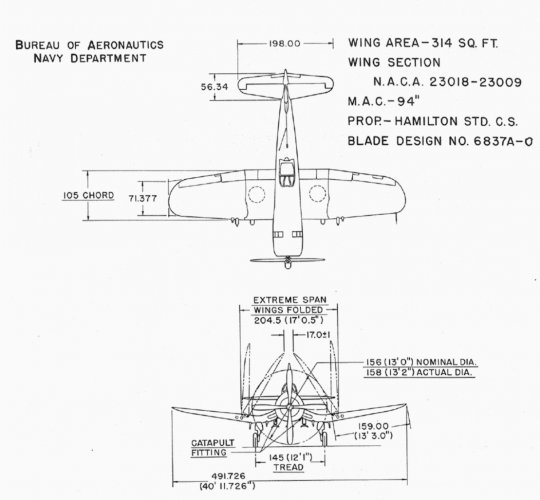
At 17%, the Whirlwind is certainly on the better par of the end of 1930´s era but certainly not aligned with the NACA 5 digit airfoils known with later props fighters that achieved 400+mph. 15% was an average maximum (Corsair, FW-190, BF-109, Tempest...).
Have a look by yourself here
Note that I just read the excellent DingerAviation post on the Whirlwind that made me dig into it.
Hi Tomcat,
Hm, I'm not quite sure how much impact that really has, especially if the assertion is that the type of propeller made a big difference for high-altitude speed.
The Dornier Do 335 had a NACA 23018-630 wing root airfoil, by the way. While that's a modified version of the original airfoil, it's still thicker than the Whirlwind's, and the Do 335 doesn't seem to have had any problem at much higher speeds and altiutudes than the Whirlwind could ever reach.
Westland's Welkin on the other hand is listed with a NACA 23021 root/NACA 23015 tip, and I believe it was indeed a disappointment due to compressibility effects, so maybe you're onto something after all.
Regards,
Henning (HoHun)
I think also there is a misunderstanding resulting from the community focusing on the Propellers.
I had a look at the Whirlwind airfoils (wing) and the thickness ratio should give us a simple answer. I don´t think there is much to look past it:
View attachment 766671
At 17%, the Whirlwind is certainly on the better par of the end of 1930´s era but certainly not aligned with the NACA 5 digit airfoils known with later props fighters that achieved 400+mph. 15% was an average maximum (Corsair, FW-190, BF-109, Tempest...).
Hm, I'm not quite sure how much impact that really has, especially if the assertion is that the type of propeller made a big difference for high-altitude speed.
The Dornier Do 335 had a NACA 23018-630 wing root airfoil, by the way. While that's a modified version of the original airfoil, it's still thicker than the Whirlwind's, and the Do 335 doesn't seem to have had any problem at much higher speeds and altiutudes than the Whirlwind could ever reach.
Westland's Welkin on the other hand is listed with a NACA 23021 root/NACA 23015 tip, and I believe it was indeed a disappointment due to compressibility effects, so maybe you're onto something after all.
Regards,
Henning (HoHun)
See the 18% value more like a design choice from Dornier earlier design for structural purpose as the leading edge is swept, with an inherent aerodynamics decrease of the profile (Aerodynamics considers the section of reference as the one perpendicular to the leading edge).
Notice also that the dash 630 mod does not make much sense isolated from the context. It might reflect an alteration along the span of the location of maximum thickness.
Notice also that the dash 630 mod does not make much sense isolated from the context. It might reflect an alteration along the span of the location of maximum thickness.
Hi Tomcat,
Here's a forum post explaining one scheme for numbering modifications:
Here's another post explaining a slightly different German scheme:
It looks to me as the 23018-630 is a modification according to the second style, with the standard NACA profile's nose radius and the location of the maximum thickness at 30% of the chord ... which seems to be standard for the airfoil, too:
 airfoiltools.com
So it seems it could well be an unmodified NACA 23018 airfoil ...
Regards,
Henning (HoHun)
Notice also that the dash 630 mod does not make much sense isolated from the context. It might reflect an alteration along the span of the location of maximum thickness.
Here's a forum post explaining one scheme for numbering modifications:
Here's another post explaining a slightly different German scheme:
It looks to me as the 23018-630 is a modification according to the second style, with the standard NACA profile's nose radius and the location of the maximum thickness at 30% of the chord ... which seems to be standard for the airfoil, too:
NACA 23018 (naca23018-il)
Details of airfoil (aerofoil)(naca23018-il) NACA 23018 NACA 23018 airfoil
So it seems it could well be an unmodified NACA 23018 airfoil ...
Regards,
Henning (HoHun)
I think also there is a misunderstanding resulting from the community focusing on the Propellers.
I had a look at the Whirlwind airfoils (wing) and the thickness ratio should give us a simple answer. I don´t think there is much to look past it:

At 17%, the Whirlwind is certainly on the better par of the end of 1930´s era but certainly not aligned with the NACA 5 digit airfoils known with later props fighters that achieved 400+mph. 15% was an average maximum (Corsair, FW-190, BF-109, Tempest...).
This datasheet shows 19% t-t-c at root for the Whirlwind.
1-engined fighters being designed in the late 1930s were mostly with t-t-c at 15% or under. Mostly British were keen to saddle their 1-engined fighters with 18-19% t-t-c (bar Supermarine with the Spitfire; the Type 224 was also with extra thick wing) + Vought with the F4U.
NAA gotten away with the ground-breaking airfoil, at 16% t-t-c.
Hi Tomcat,
To evade the potential apples-to-oranges comparison, we could use the F4U as a point of reference, which didn't seem to suffer from any high-altitude drag problem in spite of having a 23018 root airfoil, too.
Not to say I mean to blame the propeller instead, but I'm not sure the Whirlwind's airfoil was the culprit ...
Regards,
Henning (HoHun)
Yes. That exactly my take too. That's why I suggested that dashing the Naca number was the result of a geometrically varying maximum thickness location. You can see the tip being at 35% already.
To evade the potential apples-to-oranges comparison, we could use the F4U as a point of reference, which didn't seem to suffer from any high-altitude drag problem in spite of having a 23018 root airfoil, too.
Not to say I mean to blame the propeller instead, but I'm not sure the Whirlwind's airfoil was the culprit ...
Regards,
Henning (HoHun)
red admiral
ACCESS: Top Secret
- Joined
- 16 September 2006
- Messages
- 1,802
- Reaction score
- 2,363
Whirlwind also had wing root radiators so the actual t/c and drag characteristics will be quite different
Hi Tomcat,
Are you sure? It's listed as 23018 in the "incomplete list", as well as the two documents Tomo posted.
I think there's a NACA report comparing stall characteristics of F4U, F6F, P-51 and probably others which might have more details on the wings, but the type designations are not in the report nor in the abstract, so I am not quite sure how to pull that from the archives for a quick check.
Regards,
Henning (HoHun)
@HoHun : Corsair is a 23015. 15%
Are you sure? It's listed as 23018 in the "incomplete list", as well as the two documents Tomo posted.
I think there's a NACA report comparing stall characteristics of F4U, F6F, P-51 and probably others which might have more details on the wings, but the type designations are not in the report nor in the abstract, so I am not quite sure how to pull that from the archives for a quick check.
Regards,
Henning (HoHun)
Similar threads
-
-
Geoffrey Hill/Westland-Hill "Pterodactyl" Designs and Prototypes
- Started by Retrofit
- Replies: 49
-
-
-

