US Lifting Bodies Studies - START (ASSET/PRIME), FDL, X-24, etc.

hesham said:
Hi,

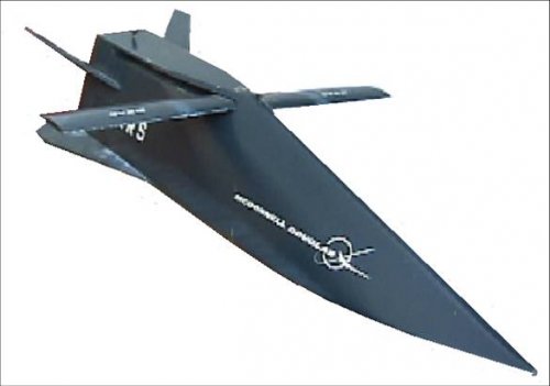
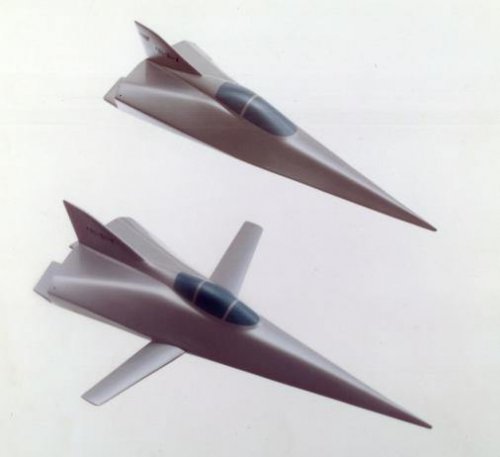
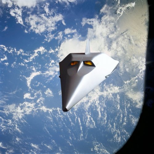
The McDonnell Douglas Model-176 was hypersonic spacecraft,but when
I search about it I found a Models of hypersonic aircraft not known,
see the picture,

Comments to picture names in the first post:
'Model 176' is true Model 176
But 'Model 176(2)' is FDL-5
Model 176 is a derivative of FDL-7MC
 
I always belived that ASSET prototypes was tightly connected with the "Winged Gemini" project, heavily sponsorized by USAF at that times.

In effect if you take an ASSET vehicle you may find out that it is a perfectly subscale model (1:2) of Winged Gemini, the thing takes more reason if you notice that McDonnell was in charge of production and development of both ASSET and Gemini.

Strangely the ASSET programme was always connected with X-20 Dynasoar project, neverthless the two vehicles had radical different configurations and not the same prime contractors as well (McDonnell vs Boeing).
 

Attachments

  • gemini winged.jpg
    gemini winged.jpg
    125.4 KB · Views: 587
  • Asset.jpg
    Asset.jpg
    125.9 KB · Views: 557
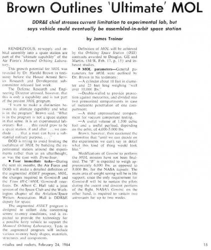
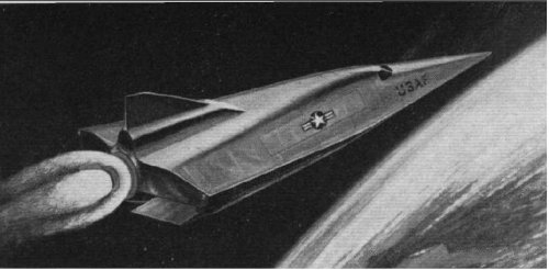
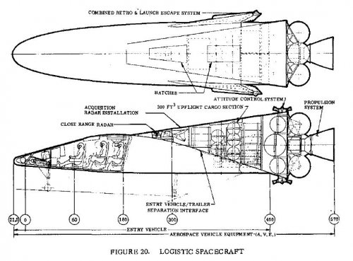
Well this article links an augmented ASSET program with a lifting body vehicle for use with MOL and it would replace Gemini.
 

Attachments

  • scan0014 (2).jpg
    scan0014 (2).jpg
    90.4 KB · Views: 436
  • scan0028 (2).jpg
    scan0028 (2).jpg
    183.4 KB · Views: 438
Source: AIAA 2004-5888
An Essential Element in Affordable Space Access is the Return Vehicle. A Historical Perspective Based on Support Vehicles
for the Manned Orbiting Laboratory, circa 1964
Paul A. Czysz
HyperTech Concepts LLC, St. Louis, Missouri 63141, U.S.A.
Claudio Bruno.
University of Rome,<LA SAPENZA> Rome Italy
Ying-Ming Lee
MSE Technology Application, Butte, Montana. U.S.A.
Space 2004 Conference and Exhibit
28 - 30 September 2004, San Diego, California

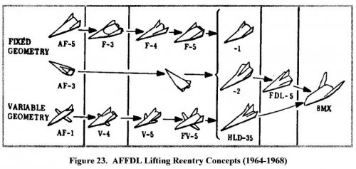
Photo shows the array of delta planform configurations that the Flight Dynamics Laboratory had considered in the 1958 to 1968 time
period. Specifically identified on the photo are:

Configuration 2 was a higher wing loading, relatively blunt all body with an upswept spatular nose that is not
unlike the BOR series of Lozino-Lozinski hypersonic gliders from Russia. Because of the longitudinal extent of the
former USSR compared to the USA, the minimum lift-to-drag ratio to assure a landing on the continental USSR
land mass. The USSR requirement is for an L/D of about 1.7, whereas for the USA it is about 2.7. Thus, the lower
lift-to-drag ratio minimizes the possibility for a Russian spacecraft to land in the continental United States without a
long waiting period.
Configuration 3 was a subscale research vehicle to evaluate the thermodynamics and materials for hypersonic
gliders. The nose and leading edge radii were full-scale size of the X-20. ASSET was successfully flown on a Thor
IRBM booster. One that was recovered from its landing in the ocean was for a time on display in the USAF Museum
in Dayton, Ohio.
Configuration 4 was a product of cooperation between the Flight Dynamics Laboratory (Alfred Draper) and
McDonnell Douglas Astronautics Company, St. Louis (Robert Masek) to develop a vehicle to support the Manned
Orbiting Laboratory (MOL). This concept was briefed to the US Air Force in 1964. The variable geometry
switchblade wing permitted landing with heavy loads returning from space, and could eventually permit horizontal
takeoff. The tail configuration was an experimentally determined configuration feature. This configuration was
wind tunnel tested and demonstrated inherent stability and control over the speed range from Mach 22 to landing
speed. Paul Czysz was at the Flight Dynamics Laboratory from 1956 to 1963 and at McDonnell from 1963
onwards witnessed these configurations being developed.
Configuration 6 was a product of the Flight Dynamics Laboratory (Richard D. Neumann) to reduce the drag
of hypersonic gliders. Based on the physics that a two-dimensional wedge has less drag the a right circular cone of
the same volume, Neumann devised the “spatular leading edge”.
It is essentially a Spatular nosed version of Configuration 5. John (Jack) Pike of the RAE and Cranfield Technical Institute developed analogous configurations independently and published the wind tunnel and analytical work in 1973. Robert Krieger of McDonnell Douglas Astronautics, St. Louis also developed a Newtonian analysis of spatular noses8. The wind-body configuration was
the basis of the X-20.
Configuration 7 and the other lifting body configurations were FDL-7C/D class of configurations with a partial
horizontal surface and a vertical control surface. Without the “X” type tail configurations of the FDL-7C/D the
control capability was reduced and the usable lift-to-drag ratio was less. But nevertheless proved instrumental in
developing the FDL high lift-to-drag ratio configurations.
Configuration 8 is a FDL version of the NASA Langley HL-10 hypersonic glider.
Configuration 9 is a model of the Ames/Eggers M2/F2 half-cone derived configuration.
Configuration 10 is an adaptation of the Russian “Star Body” concept that The limitation is the configuration
concept is severely volume limited and had a high ratio of wetted (surface) area per planform area. This is an
adaptation of that concept to the FDL class delta gliders to evaluate the controllability provided by the star configuration.
In the process of adapting the star body configuration to the FDL delta configuration, the ability to have an
independent entry orientation was lost.
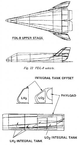
Configuration 1 is the X-24B or its AFFDL counterpart the FDL-8. It represents the different approach to hypersonic glider configurations by NASA and AFFDL. Martin Marietta built the X-24A at its Denver, Colorado facilities. The X-24A is a round fuselage configuration with outboard high dihedral angle vertical tails typical of the Ames Eggers vehicles and the Langley HL-19. All the configurations of this type have serious lateraldirectional stability problems at low speeds and tend to roll about the horizontal axis. One designer who solved the problem with variable dihedral vertical tails (+60 to –10 degrees) was Gleb Lozino-Lozinski of Russia. The Flight Dynamics Laboratory solved the problem by using flat bottom configurations. Under a USAF Flight Dynamics Laboratory program, Martin modified the X-24A into flat-bottomed configuration with trailing edge elevons called the X-24B. Bill Dana was the NASA pilot that flew the X-15, X-24A and X-24B. His comments about the change in slow speed performance with the X-24B confirmed the advantage of the Flight Dynamics Laboratory approach. The basis of the X-24B was the FDL-8 configuration.
 

Attachments

  • FDLliftingbodies1956-1965.jpg
    FDLliftingbodies1956-1965.jpg
    55.1 KB · Views: 526
How does the Resupply Vehicle work if it's unmanned? Wouldn't that make it only suitable for sending payload up to the station? What about taking the people from the station and allowing them to come down!?

BTW: How did the heat-dissipation system work?
 
Hi,

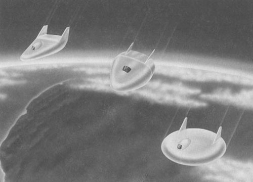
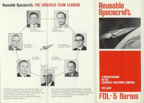
the Lockheed space vehicle project of 1968 was described as "a breakthrough
in the design of the space re-entry vehicles.
http://www.flightglobal.com/pdfarchive/view/1968/1968%20-%200064.html
 

Attachments

  • Lockheed.JPG
    Lockheed.JPG
    41.7 KB · Views: 319
archipeppe said:
It seems to be some FDL-design configuration...

FDL-5A
http://stinet.dtic.mil/cgi-bin/GetTRDoc?AD=0390193&Location=U2&doc=GetTRDoc.pdf
http://stinet.dtic.mil/cgi-bin/GetTRDoc?AD=0390194&Location=U2&doc=GetTRDoc.pdf
http://stinet.dtic.mil/cgi-bin/GetTRDoc?AD=0390195&Location=U2&doc=GetTRDoc.pdf
http://stinet.dtic.mil/cgi-bin/GetTRDoc?AD=0390196&Location=U2&doc=GetTRDoc.pdf
http://stinet.dtic.mil/cgi-bin/GetTRDoc?AD=0390205&Location=U2&doc=GetTRDoc.pdf
 
the Lockheed space vehicle project of 1968 was described as "a breakthrough
in the design of the space re-entry vehicles.

looks a lot like this image, from 'frontiers of space', bono/gatland, page 55,

cheers,
Robin.
 

Attachments

  • lockheed two-man lifting body concept.jpg
    lockheed two-man lifting body concept.jpg
    151.4 KB · Views: 473
It was the same FDL-5A object of a well known mock-up shots of late 60s???
 
FDL lifting bodies featured sharp edges and flat bottoms. NASA came close with the X-24B but then reverted back to blunt bodies? The sharp bodies are good handling much better than blunt bodies. NASA went blunt to avoid all weather metal military type TPS with piped coolant LE in favor ceramic and carbon/carbon tiles. To bad after all these years and data to the contrary NASA remains blunt minded
 
The variable geometry switchblade wing permitted landing with heavy loads returning from space

Many of the FDL and McD ILRV designs utilized switchblade wings. There were many more FDL lifting body configurations tested than pictured. I have many photo's of such however they are not yet for public consumption.

Flateric.....very impressed with your historical knowledge. I must say this forum is more grounded than others I have visited.
 
Add-on to AFFDL lifting bodies configurations collection
FDL-8 (8MX) was an interesting one, pre-pre X-33
 

Attachments

  • AFFDL_liftingbodies.jpg
    AFFDL_liftingbodies.jpg
    60.8 KB · Views: 355
Very good illustration as I had mentioned there were many other configurations tested. However most follow the same general planar wedge shape planform. I hope to release large scale RC model rocket boost glide and EDF versions (kits) of some of the switchblade designs next year.


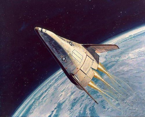
if I understand right, operational vehicles like Model 176, would be covered with *shining* reflectory metal TPS

This I can not answer for certain. Most of my data from 60's 70's era depict darker finish or coating. That could be attributed to artistic rendering in some instances. The recent Planet Space version appears to be uncoated metallic and shinny. I will pose that question to Paul when I have an opportunity. Much of the information I have gleaned comes from direct contact with some of the "Old Timers" engineers from that era. Unfortunitly they are becoming fewer in number and much of that valuable brain trust will soon be lost.
 
flateric said:
Configuration 9 is a model of the Ames/Eggers M2/F2 half-cone derived configuration.

This is actually incorrect. If you take a look at any picture of the M2-F2 it clearly has a generally flat upper fuselage surface and vertical stabilisers. The model shown is the PRIME / SV-5 / X-23/4A series.
 
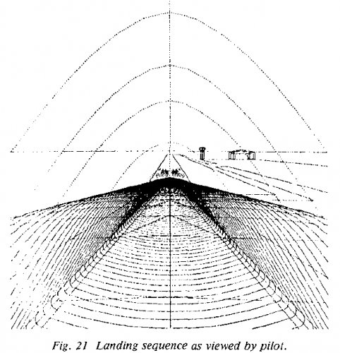
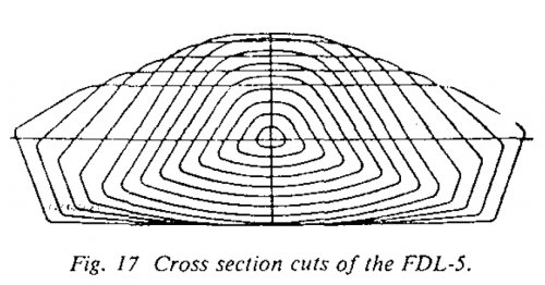
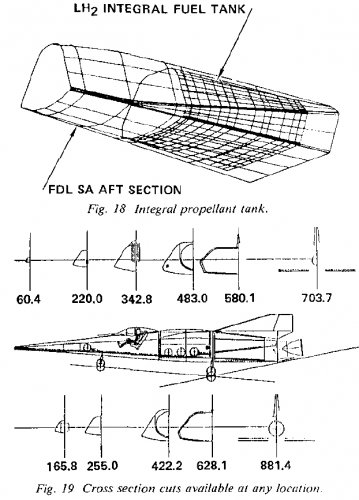
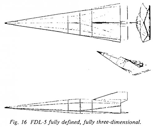
More on FDL-5 and FDL-8
 

Attachments

  • FDL-8 concepts.jpg
    FDL-8 concepts.jpg
    206.4 KB · Views: 366
  • FDL-8a.jpg
    FDL-8a.jpg
    114.4 KB · Views: 432
  • FDL-5-PILOTSVIEWONLANDING.jpg
    FDL-5-PILOTSVIEWONLANDING.jpg
    188.1 KB · Views: 387
  • FDL-5-3CROSSSECTIONS.jpg
    FDL-5-3CROSSSECTIONS.jpg
    154.4 KB · Views: 427
  • FDL-5-INBOARD.jpg
    FDL-5-INBOARD.jpg
    173.4 KB · Views: 491
  • FDL-5-3-VIEW.jpg
    FDL-5-3-VIEW.jpg
    137.5 KB · Views: 532
dart8t.jpg


Planetspace's Silver Dart re-entry vehicle based on FDL-8. It's a small company trying to raise funds for building something, they have multiple projects...

http://www.planetspace.org/lo/silver_dart.htm
http://www.planetspace.org/lo/dart_images.htm
 
What do you folks think the odds of the Silver-Dart making it to actual service are? (I mean after Spaceship One it does seem possible -- but I've seen all too many times a great design is conceived and ends up never making it to service) Also, will the production Silver-Dart have provision for a cockpit as the prototype does, (as there's a picture of a pilot in a cockpit like area) as it will be unmanned? (With a provision for being manned)

I'm glad to see someone made something out of that light-weight metal TPS system -- sure beats the ceramic tiles used on the shuttle and elaborate cooling systems like used on many high-speed designs. I take it the heat-pipe is only used in the leading edge.

According to what I found on wikipedia, Paul Csysz is working on the design...


Kendra Lesnick
BTW: I don't think I went off topic, but if I did I'm sorry
 
Planet Space appears to have loss out of the NASA COTS funding. I fear the Silver Dart is now a lost cause again as well. This design had great promise only Planet Space has yet to fly anything. Like many of the small private funded space companies big plans always looking for investors then never follow through. Take the money and run?????
 
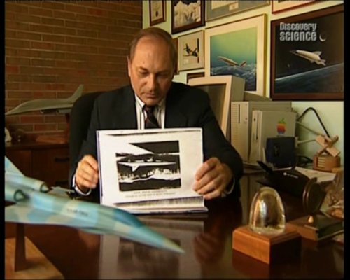
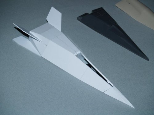
Interesting, it resembles a game of finding hidden objects on a picture. Look at the black object at the table.
We have Model-176 here...and now no questions of it's proposed color - black silicon carbide layer as on X-20.
 

Attachments

  • Clipboard02.jpg
    Clipboard02.jpg
    209.5 KB · Views: 374
  • Clipboard13.jpg
    Clipboard13.jpg
    187.1 KB · Views: 398
The tragic irony of all these lifting body design studies is that to date nothing significant beyond the Space Shuttle abomination (bus) has ever came of them. The X-24B demonstrated the advantages of flat bottomed sharp wedge profiles. The failure to follow-on with the development of the X24-C test program including more robust TPS is a historic and tragic milestone in US manned space exploration. One which continues to haunt and impact the US space industry to date and into the foreseeable future. We totally "screwed the pooch".
 
The model which sets next to Mr. Czysz phone (only the white conical lower toss back stage is visible) appears to that of the MOL "toss-back" TSTO lifting body concept. I find it to be the most promising TSTO VTHL RLV concept I've ever seen.
 
flateric said:
Look at the black object at the table.
We have Model-176 here...and now no questions of it's proposed color - black silicone carbide layer as on X-20.

I'm still not entirely so sure, as the Silver-Dart was to use the same basic TPS principle that the Model 176 was to use and is shimmering silver.


Kendra Lesnick
 
The failure to follow-on with the development of the X24-C test program including more robust TPS is a historic and tragic milestone in US manned space exploration. One which continues to haunt and impact the US space industry to date and into the foreseeable future
What do you mean exactly ?
 
NASA made some bad decisions in the 70's. Mainly the monster white elephant shuttle which sucked the funding from many high return programs such as X-15/X-24B follow-on. Stopped incremental lifting body and air breathing propulsion development. Scuttled heavy lift and abandoned the Skylab. All the infrastructure was in place in the mid seventies to develop a high flight rate RLV program to support Skylab and future deep space projects. In one clean sweep NASA burnt the bridges and chucked it all for the monster shuttle…..hindsight!
 
KJ_Lesnick said:
flateric said:
Look at the black object at the table.
We have Model-176 here...and now no questions of it's proposed color - black silicone carbide layer as on X-20.

I'm still not entirely so sure, as the Silver-Dart was to use the same basic TPS principle that the Model 176 was to use and is shimmering silver.


Kendra Lesnick

I'm judging from the several model pics and artist's impressions of Model 176 and its derivative vehicles of the era, Silver Dart being apart. Seems there were no problem to make 'em shiny silver?
Term 'refractory' not always mean 'silver'. SR-71A paint is also serves the same purpose.
 
Hi,

http://history.nasa.gov/SP-4220/ch1.htm
http://history.nasa.gov/SP-4220/ch6.htm
 

Attachments

  • p114s.jpg
    p114s.jpg
    15.8 KB · Views: 276
  • hyper III.jpg
    hyper III.jpg
    36.9 KB · Views: 238
  • p14.jpg
    p14.jpg
    21.2 KB · Views: 213
airrocket said:
if I understand right, operational vehicles like Model 176, would be covered with *shining* reflectory metal TPS

This I can not answer for certain. Most of my data from 60's 70's era depict darker finish or coating. That could be attributed to artistic rendering in some instances. The recent Planet Space version appears to be uncoated metallic and shinny.
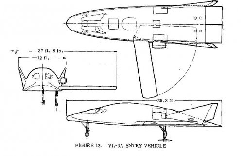
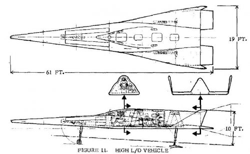
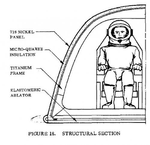
Virtually every serious proposal for a spacecraft using metallic heat shields is black. The metal itself is generally a tungsten molybdenum alloy... extremely high melt temperature. The moly alloys I've seen have tended to be a rather dull "metallic" color... not shiny, but certainly not black. The black comes from a disilicide coating to prevent oxidation (even TZM alloys will oxidize at these temperatures), and a coating of silicon carbide to greatly enhance emissivity. A white or shiny metal will take a bit longer to heat up due to radiatiative heating since it will reflect some of that heat away... but a black metal will re-radiate away that heat a lot faster. It's a tradeoff... one that has almost invariably traded in favor of black coatings.

As to why Silver Dart is silver... dunno. Marketting? Black Dart might not sound right. Or it might be silver for suborbital trials, where the heating laod is far lower and the black coating would not be as useful.
 
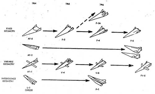
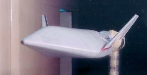
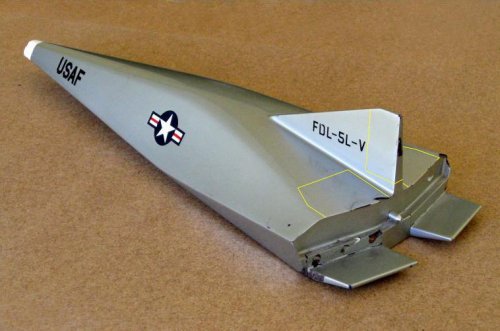
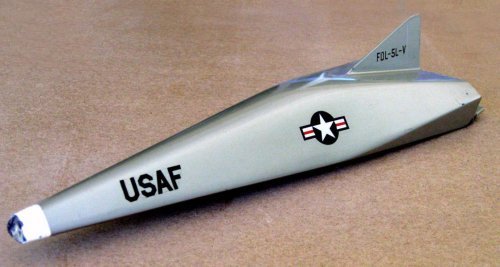
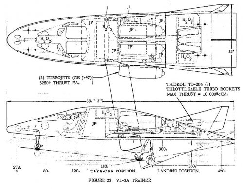
1,2). FDL-5A desktop model
3,4). FDL-5A brochure
5,6,7). FDL-5A based Space Shuttle configurations studied (60s-80s(?))
8). FDL-5A evolution chart

from AIAA 2008-2611
FDL-5A - Precursor to High Performance Lifting Entry Spacecraft: An Historical Review
by Carl F. Ehrlich, Jr.
 

Attachments

  • FDL-5A_evo.jpg
    FDL-5A_evo.jpg
    40.2 KB · Views: 327
  • FDL-5A_derived_Shuttle_final.jpg
    FDL-5A_derived_Shuttle_final.jpg
    24.5 KB · Views: 291
  • FDL-5A_derived_Shuttle_intermediate.jpg
    FDL-5A_derived_Shuttle_intermediate.jpg
    24.8 KB · Views: 276
  • FDL-5A_derived_Shuttle_60s.jpg
    FDL-5A_derived_Shuttle_60s.jpg
    20.7 KB · Views: 300
  • FDL-5A_brochure-2.jpg
    FDL-5A_brochure-2.jpg
    52.6 KB · Views: 482
  • FDL-5A_brochure-1.jpg
    FDL-5A_brochure-1.jpg
    38.4 KB · Views: 492
  • FDL-5A_DM-2.jpg
    FDL-5A_DM-2.jpg
    48.8 KB · Views: 471
  • FDL-5A_DM-1.jpg
    FDL-5A_DM-1.jpg
    86.3 KB · Views: 493
1). FDL-5A shape derived Rockwell International AMSC concept from 80s
AMSC = Advanced Military Spaceflight Capability Technology Identification Study
2). FDL-5A based air-launched vehicle (inspired by successful Minuteman airlaunch experiments)
3). FDL-5A configuration with cockpit anf VG wing
 

Attachments

  • FDL-5A_cockpit&VGW.jpg
    FDL-5A_cockpit&VGW.jpg
    12.5 KB · Views: 366
  • FDL-5A_airlauch.jpg
    FDL-5A_airlauch.jpg
    42.3 KB · Views: 428
  • FDL-5A_derived_AMSC.jpg
    FDL-5A_derived_AMSC.jpg
    78.6 KB · Views: 455
yeeeeessss new stuff for me
thanks flateric!!!
 
1966 GD/Convair offer of post-Mercury lifting body manned orbiter. Still looking sexy.

from
THE FIRST MANNED LIFTING ENTRY VEHICLE CONFIGURATION
ROBERT A. LYNCH
General Dynamics / Convair
San Diego, California
AIAA Paper No. 66-959
 

Attachments

  • GD_1966_manned_LB-6.jpg
    GD_1966_manned_LB-6.jpg
    145.4 KB · Views: 359
  • GD_1966_manned_LB-5.jpg
    GD_1966_manned_LB-5.jpg
    78.8 KB · Views: 283
  • GD_1966_manned_LB-4.jpg
    GD_1966_manned_LB-4.jpg
    91.8 KB · Views: 304
  • GD_1966_manned_LB-3.jpg
    GD_1966_manned_LB-3.jpg
    45 KB · Views: 247
  • GD_1966_manned_LB-2.jpg
    GD_1966_manned_LB-2.jpg
    53.9 KB · Views: 325
  • GD_1966_manned_LB-1.jpg
    GD_1966_manned_LB-1.jpg
    57.7 KB · Views: 365
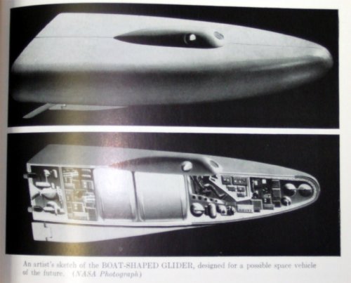
some very old stuff found in ILR archive in Aachen Germany

Source:

Principles of guides missile design from 1960

note: picture taken with digicam
 

Attachments

  • Delta_wing_Glider.jpg
    Delta_wing_Glider.jpg
    151.4 KB · Views: 249
  • Boat_shaped_glider.jpg
    Boat_shaped_glider.jpg
    175.7 KB · Views: 272
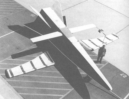
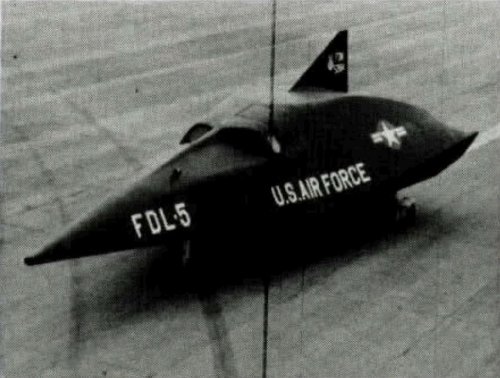
Another FDL-5 mock-up pic
 

Attachments

  • FDL.jpg
    FDL.jpg
    79 KB · Views: 318
Michel Van said:
some very old stuff found in ILR archive in Aachen Germany

Source:

Principles of guides missile design from 1960

note: picture taken with digicam

I could swear I've seen those on the forum before - but where - I can't say ???
 
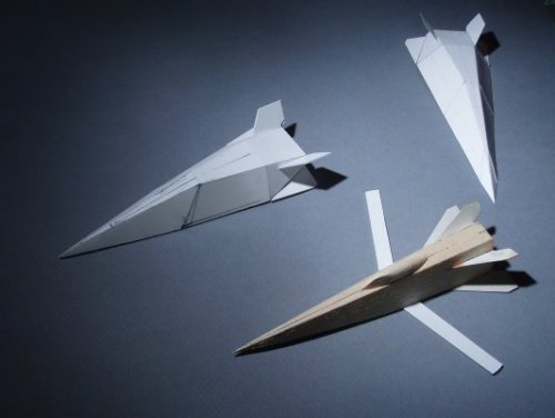
Stephane Cochin (Stratosphere Models) back on track with his beautiful models
http://www.picturetrail.com/gallery/view?p=6&uid=2335047&
Photos (c) Stratosphere Models.
 

Attachments

  • 151678849.jpg
    151678849.jpg
    39.5 KB · Views: 266
  • 280989056.jpg
    280989056.jpg
    120.8 KB · Views: 268
  • 311077541.jpg
    311077541.jpg
    76.3 KB · Views: 272

Similar threads

Please donate to support the forum.

Back
Top Bottom