Sukhoi Su-57 / T-50 / PAK FA - flight testing and development Part II [2012-current]

So, yeah trying to make an infographics on range and coverage of Su-57 Radar. Assumptions are listed in the image.

For this i tried to make the image more "informative" by providing and taking account of probability of detection (aka signal strength) 50% is where the target will begin to be detected while 90% is where the signal strength is strong enough to allow continuous tracking with high confidence or even engagement with weapons (Lock on etc).
 

Attachments

  • N036Estimate-8-13-2020.png
    N036Estimate-8-13-2020.png
    979.9 KB · Views: 246
So, yeah trying to make an infographics on range and coverage of Su-57 Radar. Assumptions are listed in the image.

Very interesting Stealthflanker, I have a few doubts:

> How many L band arrays per side are you considering? In the wings only or also in the LERX? There seems to be radiotransparent material in both.
> Are you considering the same detection range for the whole deflection aspects of the radar beam? Would this be realistic or would the range decrease with the increased deflection angle?
> You say "50% search capacity, 50% others is used for tracking"; that means, the radar is searching and tracking targets at the same time? Would detection ranges change if it was only searching, or only scan time would be increased?
> For the tracking range, are you considering focusing the beam or just considering the distance at which signal strength is high enough while keeping the same scan pattern?

All in all, a great contribution, in fact I never thought the L band radar could have such significant detection range...

The wing array. Like, is the LERX part of the Radar or the part of Himalaya suite ?. I incline to believe that the Levcon one is part of Himalaya suite mainly because possibility in difficulty of placing cooling system inside it. In the other hand the wing array would have ample of space plus being near the wing tank, thus may allow shorter and perhaps lighter piping for cooling purpose. This in turn allows large cooling capacity which allows growth of the wing array into radar. While ECM array, particularly self defense may not necessarily needs powerful cooling as they only emit in tens to at most 100-200 Watts Thus it can be in the Levcon.

And yes, Multifunction radar array found in usual fighter aircraft do share its capacity for tracking and search. You can look into Sabatini and M.Tarantino's Book "Multifunctional Radar Array" for relevant informations. And obviously since the time and power is shared between the search and tracking activity, detection range would change too. It is the feature of my AESA Radar Calculator. Typical assumption however is 50% search-track. If one say... devote more radar resources for search, detection range would be longer, while if tracking gets more priority, the amount of targets your radar can track increases. and All of that have to happen in the "Frame time" or the total scan time. e.g 5 seconds.

The tracking range is basically the range where the signal strength sufficient for 90% PD. Focusing the beam is TBH a weird term as by all means a directional antenna like one in radar is already "focused" It can only be "de-focused" or the beam is "enlarged" by change of antenna weighting (e.g Taylor -40 dB to Cos^5) Which changes the angular resolution.

The range vs beam deflection angle is an interesting consideration. The range might decrease as beam deflected further due to beam broadening caused by aperture foreshortening and scan loss. Nonetheless the "Fan" representation is easier to understand.
 
@stealthflanker ,
But what about the elevation resolution for wing antennas? The height size is clearly not enough for the required beam width. For L-band.
 
@stealthflanker ,
But what about the elevation resolution for wing antennas? The height size is clearly not enough for the required beam width. For L-band.

Do you need any ? That's the first question.

If the array is only meant for early warning. it may not necessarily need heightfinding capability. If such capability is required then it is either :

1.Have to be provided by another array e.g rudder.
2.Have to be provided via Multipath heightfinding.

the #1 is unlikely as we see no such installation apparent in Su-57, Thus if the leading edge array do operate as radar and someone wants heightfinding capability, it has to be provided via #2, which were happen to be used in E-2 Hawkeye. This however will constrain the operating altitude of the aircraft.
 
@stealthflanker ,
I think everything is much simpler. These are just IFF(Identification, friend or foe) antennas, for which the elevation angle is really not very important.
More details here.
Russian Language :rolleyes:

Well 2D radar like one you see in airport does not have heightfinding capability either, it got its altitude information from the IFF. or in case of military radar a dedicated nodding heightfinder.

I am fully understand the paper and that one promotional brochure from KRET on the IFF. Nonetheless I cannot easily ignore the fact that it does have potential plus IFF can be one of its operating mode.
 
The wing array. Like, is the LERX part of the Radar or the part of Himalaya suite ?.

I don't reach a conclusive opinion based on the pictures I saw. The 057 has radiation signs in the LEVCONS but not on the wings as far as I have seen. Then this picture shows all apertures in LE, LEVCON, wing tips and nose marked with a radiation sign, I had not seen this in the prototypes before. The length of the arrays in the LEVCONS and wings are roughly of the same size, couldn't they be both L-band radar and ECM emitters?

su-57 antenas said pvo.jpg
I incline to believe that the Levcon one is part of Himalaya suite mainly because possibility in difficulty of placing cooling system inside it.

There is the dorsal tank very close too. The array in the LE would need flexible cooling piping too...
And yes, Multifunction radar array found in usual fighter aircraft do share its capacity for tracking and search. You can look into Sabatini and M.Tarantino's Book "Multifunctional Radar Array" for relevant informations. And obviously since the time and power is shared between the search and tracking activity, detection range would change too. It is the feature of my AESA Radar Calculator. Typical assumption however is 50% search-track. If one say... devote more radar resources for search, detection range would be longer, while if tracking gets more priority, the amount of targets your radar can track increases. and All of that have to happen in the "Frame time" or the total scan time. e.g 5 seconds.

Great, thanks for clarifying. Does the this power sharing mean that there multiple beam forming going on?
Focusing the beam is TBH a weird term as by all means a directional antenna like one in radar is already "focused" It can only be "de-focused" or the beam is "enlarged" by change of antenna weighting (e.g Taylor -40 dB to Cos^5) Which changes the angular resolution.

I meant the fighter focusing all its power in a reduced sector of the airspace, I understand this cued search option does exist in other radars.

The range vs beam deflection angle is an interesting consideration. The range might decrease as beam deflected further due to beam broadening caused by aperture foreshortening and scan loss. Nonetheless the "Fan" representation is easier to understand.

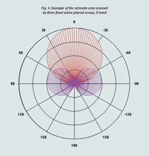
I assumed it was represented that way to make it more understandable, other representations I saw looked like this:

Polar.png
 
I don't reach a conclusive opinion based on the pictures I saw. The 057 has radiation signs in the LEVCONS but not on the wings as far as I have seen. Then this picture shows all apertures in LE, LEVCON, wing tips and nose marked with a radiation sign, I had not seen this in the prototypes before. The length of the arrays in the LEVCONS and wings are roughly of the same size, couldn't they be both L-band radar and ECM emitters?

Doubtful as Radar doesn't have and cannot jam outside of its operating band. ECM Antenna works in much broader frequency and therefore cannot have the same optimization as one for Radar.

The only other scenario is FMCW Operating mode where one of the array would continuosly transmitting while others receiving. Which make me curious whether there is enough space to still put the jammer array.

The linear array size is determined by its frequency and then spacing. 1500 MHz for Radar operation is aout 20 cm of wavelength, assume half wavelength spacing it would need about 10 cm of spacing for each element. Thus the total array length for 12 elements would be about 1.2 m still maybe enough space for a jammer. But if one desires 24 elements that would make it 2.4 m. If the operating frequency is lower for inclusion of IFF mode (making it 1000 MHz or 30 cm wavelength) The array size would be longer. 12 elements would be 1.8 while 24 would be 3.6m. There could be compromise by 16 elements but should radar operations is desired one would want as many TRM's packed as possible. due to N^3 relationship between range vs elements count.


There is the dorsal tank very close too. The array in the LE would need flexible cooling piping too...

and how often it would move ? It's kinda rare to see fighter aircraft use its leading edge device for something other than enhancing lift during take-off. While the Levcon one is actively used. dont that mean if the Levcon array is a radar it would need some form of stronger piping.


Great, thanks for clarifying. Does the this power sharing mean that there multiple beam forming going on?

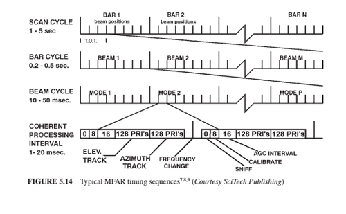
No, you share the time. This is how fighter radar "Scan pattern" looks like

Radar scan cycles.png

The modes are "interleaved" in the beam cycle. So the radar is roughly scanned like a TV raster where each raster bar contains the beam spot, each beam spot stays for few miliseconds or microseconds, at that time frame several modes are performed and received.

Multiple beam forming is possible but this is basically complicates your array pattern and adversely sacrifice the power aperture product of the array.


I meant the fighter focusing all its power in a reduced sector of the airspace, I understand this cued search option does exist in other radars.

I assume 120 degrees fan. If the scan sector is reduced, you would get more ranges. At least to the limit of the integration loss.

I assumed it was represented that way to make it more understandable, other representations I saw looked like this:

Yeah and did those lobes depicts range ? It may be more realistic in terms of depicting coverage, but are you sure you want to put all the different range value there ?
 
@stealthflanker ,
Please tell me two parameters from your calculation for the main (nasal) AESA:
1. What is your receiver sensitivity(dBm)?
2. What is the transmitted power of the entire AESA(dBm)?

Thanks in advance.
 
@stealthflanker ,
Please tell me two parameters from your calculation for the main (nasal) AESA:
1. What is your receiver sensitivity(dBm)?
2. What is the transmitted power of the entire AESA(dBm)?

Thanks in advance.


1.Receiver sensitivity is as follows :

System Temperature (Ts) : 968K
Receiver bandwidth (Bn) : 1 Mhz or (1000000 Hz)
Effective detectability factor : 17.71 dB (59.08) for 90% detection probability for 50% detection probability it would be 10.86 dB (12.19)

Receiver sensitivity in Watt is therefore :

S= 1.38*10^-23 * 968 * 1000000 * 59.08
S= 7.89 * 10^-13 Watt or -121 dB for 90% detection probability.

In dBm it would be :

S(dbm)=10*LOG(7.89 * 10^-13/10^-3)
S(dBm)= - 91.02 dBm for 90% detection probability while for 50% it would be -98.38 dBm


2. For power it is the following :

Peak power = 15520 Watt or 71.9 dBm
Average power (30% duty cycle) = 66.6 dBm

Hope that helps.
 
This does not appear to fully represent a “Second Stage” airframe structure. Note the missing attachment near the upper outboard corner of the inlet.
This is not a real 057. It even not a real plane. It's a KNS - a complex mock up for ground training.
This is nonsense. It is a real plane, it even did taxi tests. It is just a frame destined to be ground tester for a number of systems and will never fly and is made of real, but not flight allowed parts. Calling it mock up is completely incorrect. There is no such thing as "real" 057 anyway. T-50-7 is a static testing frame (in the classical sense, strength of the airframe testing) but it never got a b/n. They slapped 057 on T-50-KNS pretty randomly, it doesnt mean much, could have been 069 or 420 for that matter.
 
Last edited:
So, yeah trying to make an infographics on range and coverage of Su-57 Radar. Assumptions are listed in the image.

For this i tried to make the image more "informative" by providing and taking account of probability of detection (aka signal strength) 50% is where the target will begin to be detected while 90% is where the signal strength is strong enough to allow continuous tracking with high confidence or even engagement with weapons (Lock on etc).
Just curious, if you were to do this math for Su-35S, what sort of numbers would you get? Because we know, somewhat, numbers for Su-35S. One piece of the puzzle;

View: https://www.youtube.com/watch?v=cieLN4_tn0A
 
It is a real plane, it even did taxi tests. It is just a frame destined to be ground tester for a number of systems and will never fly and is made of real, but not flight allowed parts.
You're right, my dear. But english is not my native language so maybe a word 'mockup' is wrong. KNS stands for Kompleksniy Naturniy Stend - a Complex Test Model. And all its part are flight allowed except fuselage. You can compare the windshield of 057 with any other flying T-50 - the 057 has a thin windshield frame. I can say that 057 is ANTI 50-7. Whlist 50-7 has a real airframe and no other equipment, the 057 has all real equipment and mockup airframe that is not intended to fly. And for me 'a plane' is a thing that can fly. If it can't fly than it's not a 'real plane'.
 
Last edited:
Doubtful as Radar doesn't have and cannot jam outside of its operating band. ECM Antenna works in much broader frequency and therefore cannot have the same optimization as one for Radar.

True, though I had understood modern radars had antenna design that allowed for a slightly broader band. In any case, wouldn't a X band radar be an effective jammer of other radar in the same band, even if the center frequency is not exactly the same for all radars? I guess the design of the radome is also different, since they are transparent only at certain frequencies...

The linear array size is determined by its frequency and then spacing. 1500 MHz for Radar operation is aout 20 cm of wavelength, assume half wavelength spacing it would need about 10 cm of spacing for each element. Thus the total array length for 12 elements would be about 1.2 m still maybe enough space for a jammer. But if one desires 24 elements that would make it 2.4 m. If the operating frequency is lower for inclusion of IFF mode (making it 1000 MHz or 30 cm wavelength) The array size would be longer. 12 elements would be 1.8 while 24 would be 3.6m. There could be compromise by 16 elements but should radar operations is desired one would want as many TRM's packed as possible. due to N^3 relationship between range vs elements count.

In X band is difficult to interleave emitters for other frequencies between the main radar elements, but would not this be possible for bigger wavelengths? Maybe the L band radar can include also broadband emitters for the jamming system?

and how often it would move ? It's kinda rare to see fighter aircraft use its leading edge device for something other than enhancing lift during take-off. While the Levcon one is actively used. dont that mean if the Levcon array is a radar it would need some form of stronger piping.

For all that we know, the so-called LEVCONS in the Su-57 work no differently than a LE flap. If you notice, their deflection is always the same as the wing's LE flaps and seem to fulfil the same purpose of delaying airflow separation at increased AoA.

The modes are "interleaved" in the beam cycle. So the radar is roughly scanned like a TV raster where each raster bar contains the beam spot, each beam spot stays for few miliseconds or microseconds, at that time frame several modes are performed and received.

Multiple beam forming is possible but this is basically complicates your array pattern and adversely sacrifice the power aperture product of the array.

Great explanation, I thought AESA was actually using multiple beams in order to increase the number of tracked targets, but clearly it would be detrimental to concurrent search modes. Maybe multiple beam forming makes sense when time multiplexed with full array power search function and when signal is strong enough to keep track of a target even with a fraction of the array's power?

I assume 120 degrees fan. If the scan sector is reduced, you would get more ranges. At least to the limit of the integration loss.

Understood, thanks

Yeah and did those lobes depicts range ? It may be more realistic in terms of depicting coverage, but are you sure you want to put all the different range value there ?

I assume the size of the radar field depicted represented their relative strength, but I don't know the type of scale used. This appeared in KRET's Radio Electronic Technology #2/2015, page 27, probably you have already seen it.
 
Last edited:
I always thought the L-Band Array was slaved to the IFF on the Radar Complex, and ONLY for that purpose.
When you think about it, getting the IFF interegation out as early as possible, that tells you actually have Friendlies in foreward Sector, do several advantage for you;

You know at an early stage/long range that you have Friendlies, so that you can concentrate on the "contacts" that are not IFF friendlies, IMO Unknown Contacts(Bogey), they would ofc remain unknowns until you are at a closer range, until you have ID on them(Bogey/Bandit) from other means, but then you have already "filtered" away your friendly contacts, which make for an easier time managing the Area of Operation.
Also knowing who's your friendly contacts, also help when doing Tactical operation.. it all starts from Pre-planning(Pre-flight) stage.
This L-Band IFF is just another tool to make this easier, granted it does this at increased range.

I have some knowledge of IFF interegation from Prior Naval service.
 
Last edited:
I always thought the L-Band Array was slaved to the IFF on the Radar Complex, and ONLY for that purpose.
I thought it was known SINCE 2009 but world is still full of enthusiasts
 
I thought it was known SINCE 2009 but world is still full of enthusiasts

Would you mind pointing out for us laymen where is the catch? Were stealthflanker's assumptions far off? With the RCS and module power he is using, range is substantial. I mean, we don't know exactly how a modern VLO fighter or missile looks in L band after all...
 
I always thought the L-Band Array was slaved to the IFF on the Radar Complex, and ONLY for that purpose.
I thought it was known SINCE 2009 but world is still full of enthusiasts

Well... the idea of using the entire wingspan for an antenna in order to better pick up on faint returns from a B-2 stealth bomber is the type of idea that gets enthusiasm... and a four ship flight sharing data from both l-band and x-band radars to act like a single giant multi-band antenna in order to render the F-22 obsolete would seemingly make sense - a logical asymmetric response to American over-investment in signature reduction.
 
In X band is difficult to interleave emitters for other frequencies between the main radar elements, but would not this be possible for bigger wavelengths? Maybe the L band radar can include also broadband emitters for the jamming system?

You will have isolation problem considering the proximity of the jammer antenna and the radar. Imagine the jammer operating and the radar is receiving signal, the power from the jammer, though out of band may still couple to the radar and to the receiver, with some bad possibility ranged from overloading to catastrophic damage. Isolation could be gained from say having a polarization screen but Since jammer usually needs to fight against wide scale of polarization it will likely have circular pol. While Radar is usually vertical or horizontal. Thus isolation may only provide not much.. 3 dB. For isolation to work it has to be complete the opposite polarization from the radar or jammer. This will provide 25 dB.

But the best would be to put some distance like what you see in jammer aircrats such as EA-18's where the ESM Array is at wingtip while the jammer is located elsewhere.


Great explanation, I thought AESA was actually using multiple beams in order to increase the number of tracked targets, but clearly it would be detrimental to concurrent search modes. Maybe multiple beam forming makes sense when time multiplexed with full array power search function and when signal is strong enough to keep track of a target even with a fraction of the array's power?

Well it would make sense when you want to counter jamming without actually having to devote extra weight and space for guard horn or sidelobe canceller. In theory you would have N-1 numbers of channel for countering jamming where N is the number of your element.

For search you want to actually widen the beamwidth so it can cover search area quickly, weigh it against emitted power and switch back to narrower beam once target is found. This is the Flexibility that electronically scanned array covers.

I assume the size of the radar field depicted represented their relative strength, but I don't know the type of scale used. This appeared in KRET's Radio Electronic Technology #2/2015, page 27, probably you have already seen it.

Well i have but, why should i use that type of presentation ?

Well... the idea of using the entire wingspan for an antenna in order to better pick up on faint returns from a B-2 stealth bomber is the type of idea that gets enthusiasm... and a four ship flight sharing data from both l-band and x-band radars to act like a single giant multi-band antenna in order to render the F-22 obsolete would seemingly make sense - a logical asymmetric response to American over-investment in signature reduction.

Yeah, and it was at least an idea. I mean i remember C. GIbson's book on British AEW development sample page on this forum it does shows concept of British AEW with leading edge array, and i think at some point there was even USN AEW for Hawkeye replacement with the joint wint also features leading edge array. If they do think that way, why not Su-57's.

On the bigger picture i would like to show that Radar range equation is not just a Gutted form only containing RCS from some 1990's papers on judging the merit of stealth. Naturally i want to put it into good use.

But then again. I am fully aware of that paper, those KRET promotional figure and the fact that the test array does not feature some extensive cooling solution. For IFF Application this make sense as it only need to emit tens of watts.

Just curious, if you were to do this math for Su-35S, what sort of numbers would you get? Because we know, somewhat, numbers for Su-35S. One piece of the puzzle;


Well so far, what i was able to get was estimate on the target's RCS. The targets being picked have about 0.6-0.7 sqm RCS. More than that i would actually need to learn Russia as i have to know what modes being used. I could probably try to extrapolate or just use numbers from MiG-29's (as PRF, Pulsewidth are known for modes) But It might not be reliable considering technological differences.
 
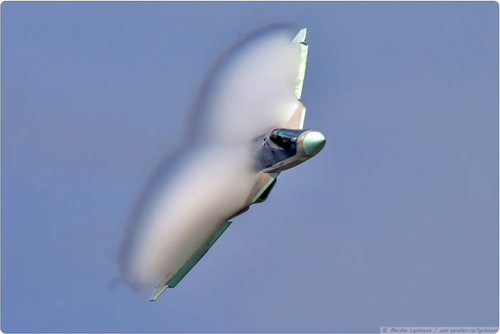
On the video above, notice how engines are smoking only when the howling sound is heard.

I was wondering what causes both the noise and the smoke? Is it something to do with the engine core? Or something else entirely different.
 
On the video above, notice how engines are smoking only when the howling sound is heard.

I was wondering what causes both the noise and the smoke? Is it something to do with the engine core? Or something else entirely different.
Perhaps turbulent air? More likely something to due with afterburner ramp-up/ramp-down
 
The pilot went out of afterburners for a few seconds, you can tell by looking and the exhaust smoke colors, I don't think he was demonstrating the best turn rate, or maybe he had to get off the re-heat to make his turn smaller, jets with excess power can turn too wide because accelerate out of their best turning speed. Ukrainian pilots flying the su-27 during airshows also do this a lot, they get off the afterburner before completing the maneuver, so we don't get to see a 360º turn on full burner or power. Did they lift the g-limit restrictions already? Are they demonstrating 9g maneuvers?
 
Analysis or estimates from video tapes or vids is a good method. It needs however an accompanying data e.g speed etc. Plus counting any restrictions it would only tell "what the pilot is doing"

Attached here is 1989 Su-27 airshow analysis by Andrew.M Skow. As seen it is accompanied by post flight pilot interview.
 

Attachments

  • skow1990-Su27 Estimate.pdf
    1 MB · Views: 36
@stealthflanker Hello.
I had a free minute, and I decided to take a closer look at your data on H036. I also looked at your excel files with a calculator. But I'm not sure if I came across the latest version of them.

Where would I start.
I would calculate the antenna array more accurately. I also apologize that I am writing about this in this thread and do not mind if the gentlemen moderators move this message to a more appropriate section.
I will not write the formulas, so as not to take time, but if there are questions, I will definitely present them.

We have 1526 modules and dimensions 900 x 700 mm.
Ellips.
The area of eleps I got 494800.84 m2
Let's assume that the usable area is 95% or 470060.8 m2.
The area of one element is 308.03 m2
The element itself can be viewed as a square or as a rectangle with an aspect ratio of 9/7 (900/700).
In a ray with a rectangle, we still need to come to the middle step. Therefore, any idea will give us an antenna array pitch of about 17.5 mm.
Since the beam is deflected by 60 degrees, the optimal (average) wavelength will be 32.7-33 mm. Accordingly, the frequency is 9.15 GHz.
The beam width is 2.48 degrees.
Directivity 5507 or 37.4 dB.
What else do we need?
These are the two questions I asked earlier:
1. Output power.
2. Receiver sensitivity.

You have assumed that each module has a power output of 10 watts. I have not seen such data in open sources. I would be grateful if you give a link.

With the receiver sensitivity, I did not quite understand your algorithm, so I will try based on my knowledge and experience.
Thermal noise at room temperature is -114 dBm per 1 MHz. Receiver noise 3dB. The signal-to-noise ratio during detection with a probability of 50% should be at the level of 8-10 dB.
Also, I don't completely agree with the bandwidth. 1MHz is not enough.
Again, based on my experience, I think, not less than 20 MHz.
-114 + 13 + 3 + 10 = -88 dBm.
Various signal processing and analysis methods can increase the receiver's sensitivity. Therefore, I consider your figure of -98 dBm to be close to the truth. Intuition suggests that this parameter varies in the range of -94 - -97 dBm.

As you can see, there is a lot of input data. And practically all of us are unknown. All of them are taken on the basis of experience and can naturally differ from reality.
Your calculation and calculator, of course, is a great creation, but there are a lot of "buts" in it.
 
The pilot went out of afterburners for a few seconds, you can tell by looking and the exhaust smoke colors, I don't think he was demonstrating the best turn rate, or maybe he had to get off the re-heat to make his turn smaller, jets with excess power can turn too wide because accelerate out of their best turning speed. Ukrainian pilots flying the su-27 during airshows also do this a lot, they get off the afterburner before completing the maneuver, so we don't get to see a 360º turn on full burner or power. Did they lift the g-limit restrictions already? Are they demonstrating 9g maneuvers?

I Generaly agree with you. It can be that enpass speed is too high for display routine, hense lots of juggling with Dry/Reheat thrust, hense the smoke.
That last 360'ish was something of a high energy turn, well at least as far as i can recall seeing on the Su-57 before.
Prior it has mostly been slow speed with inst turns acompanied.

But do keep in mind, it has TVC with that means it can do corner and turns differently vs Legacy Su-27.
 
The video above,starting to turn from 3:36 till 3:55.
360°/19s

19º/s is nothing stellar at low altitude, but we don't know fuel load, start and finish altitude and more importantly start and finish speed. We also dont know how hard was the pilot going on the stick and throttle... in general I very much doubt the pilots are going to demonstrate the ultimate turning characteristics of the plane at an airshow, Russians don't even specify the empty weights of their fighters...
 

Please donate to support the forum.

Back
Top Bottom