I wanted to do a bit of analysis on the design itself. According to Dr. Raymer's aircraft design book, Amax (the cross-sectional area of the aircraft which is largest) has a large contribution to wave drag and reducing this value can result in a less draggy aircraft than simply smoothing out the volume distribution would. For that reason, I decided to try to estimate what Amax might be for the T-50.
Very often it seems that the wing contributes largely to the volume of an aircraft and is therefore where Amax is most likely to be. I figured there were two likely places to start on the wing to determine the location of Amax: the point where the root chord is thickest, and the point where the wingspan is at a maximum. I initially thought that Amax would be somewhere between these two points, but for the T-50 at least, my calculations suggested that it was right at the leading edge of the wingtip. If this is true, then that means that Amax for the T-50 is located about 71% down the length of the aircraft (assuming length is 0% at the tip of the nose and 100% at the tip of the tail sting). This is quite a bit further down than the 50% suggested for the ideal Sears-Haack body shape, but this is expected since the T-50 is likely optimized for speeds a good bit above Mach 1. This high speed efficiency would require the rearward bias of Amax that we see.
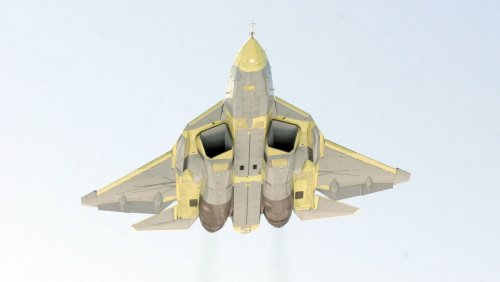
I used Matej's 5-view of the T-50 in order to attempt to reconstruct the cross-section at the predicted point of Amax, but I'm not sure how well I did (some critical features were hard to see. It's not his fault; it's just a limitation of 5-views in general). One critical piece of information I was missing was the percent thickness of the wings. For this reason, I made 3 different estimations assuming different degrees of thickness. In one, I assumed the wings were 4% thick (the same as the F-16). For the second, 6% (similar to the F-22). Finally, 8% (a very high thickness for a fighter). Initially, I didn't think thickness would affect Amax very much. It seemed to me that the differences were significant, however.
If the wingspan of the T-50 is 14 meters (another uncertainty; for me at least), I end up with the following calculations for Amax.
4% thick = 8.2 square meters
6% thick = 9.6 square meters
8% thick = 10.9 square meters
The reason I didn't go past the tenths place was due to uncertainty; working with pixels leaves a lot to be desired. For this reason, along with some of the difficulties involved in the determining the geometry of the aircraft, I would only consider these ballpark figures. To be perfectly honest, I don't know what a "normal" value for Amax would likely be. Can anyone else shed light on whether these numbers sound reasonable or not? I might end up doing a similar analysis for the F-22A in order to do a comparison. Perhaps the YF-23 as well.
Criticisms of my technique and suggestions for improvement are welcome. By the way, I did remember to subtract the capture area of the inlets when making these estimates.
EDIT: I just used
Paralay's detailed T-50 schematics to do another measurement. This time Amax came out around 5.13 square meters. That's a very large margin of error compared to my initial estimates. However, he conveniently had a cross-section drawn of the part I needed, and it looked better than my own drawing. I'd trust this second measurement over the first bunch (it's also closer to the given Amax for Dr. Raymer's Lightweight Supercruise Fighter concept in the back of his book, which he lists at 1.586 square meters. Keep in mind that his LWSF is significantly smaller than the T-50). The airfoil thickness in his drawing appears to be around 4.6% thick, which is not unreasonable. Just to be thorough, however, I'll do a quick estimate of other airfoil thicknesses (I found it interesting how Amax varied almost linearly with thickness for my initial estimates. That probably wouldn't hold true for exceedingly thick or exceedingly thin airfoils, but it should be a good guideline for simple extrapolation):
If Amax = 5.13 square meters for 4.6% thickness, then:
4% thickness
~ 4.9 square meters
6% thickness
~ 5.7 square meters
8% thickness
~ 6.5 square meters


