Eagle came before the Falcon in WW1 so why not name the second H config after the Eagle II.. the Falcon II... to be honest I don't know the answer but now I know the question I'll look into it!
In researching the supercharging of aero engines I was intrigued to see that Szydlowski-Planiol of Turbomeca researched such devices from 1938 and the military insisted that comparisons of the Hispano-Suiza 12Ygrs, for the Dewoitine D520 aircraft be made, We know from Rod Banks's 'I kept No Diary' that H-S designed poor superchargers and he was trying to get RR to help them. In the event the French Government were going to put the Merlin into the D520 and had all but negotiated a manufacturing licence for Ford of France when the Germans attacked and made the deal irrelevant. In the meantime the comparisons showed that:
The Turbomeca supercharger gave an extra 3,000 feet on full throttle height but also gave an extra 100 hp at take-off for the same inlet pressure.. result was that this supercharger became standard for the D520 and the 12Y-45 engine as it was called went into production.
Why is this relevant to Crecy?
Before the war Spike Corbitt, chief engineer for the Crecy after Dick Thomas,had visited Josef Szydlowski (JS) in France and seen the supercharger and had been impressed with the design, which improved the efficiency of the 12Y-45 by as much as 15% under certain operating conditions. As the Crecy was PI and did not have a carburetor it was worth thinking about doing a 'Szyd' to pick up the benefits too.
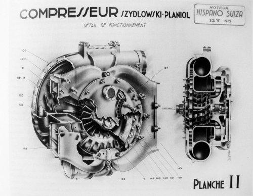
What JS had done was to fit variable intake guide vanes fed by a plenum chamber to swirl air into the eye of the impeller and so reduce the losses. JS's patent GB503652 (see sketch below) shows the setup.
abstract reads:
"Centrifugal blowers. SZYDLOWSKI, J., and PLANIOL, A. P. E. March 10, 1938, No. 7474. Convention date, March 10, 1937. [Class 110 (i)] A centrifugal blower with adjustable inlet guide vanes has a single inlet and the rotor carries on the suction side of the impeller blades 1b, Fig. 7, a set of blades 2a .. 2c to impart considerable deviation to the inlet fluid without shock or separation. The inlet vanes 7 are mounted on a pivot axis 5 and may be controlled by hand or automatically; additional vanes 7a, 7b may be carried by a movable frame 8, vanes 7a imparting a negative component of rotation to the fluid, vanes. 7b a positive component, and vanes 7 no component. The blades 2a . 2c are spaced so that the fluid stream from any blade in one set passes between two blades of the following set and.their edges may be connected by a rim. Each set of blades may consist of blades 9, Fig. 11, 'of light metal with prismatic bases 10 clamped around the shaft 12 by steel hoops 11 preferably shrunk on. When the blower is used as a supercharger, the inlet vanes 7 may replace the butterfly valve of the carburetter. Outlet guide vanes may be used, as described in Specification 484,373."
Gerry Wells, a member of AEHS, has researched the S-P supercharger and his members-only essay includes a cutaway (second attachment). The vanes we are interested in are labelled V.
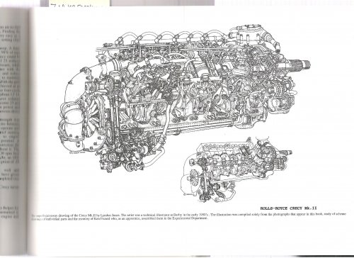
As I have been used to looking at Merlin pictures with the carburetter before the s'charger intake it had not registered that the two spindles I could see at the inlet to the supercharger on the Crecy were different. They are the axes of rotation of two butterfly throttle valves that aso act to swirl the inlet air in a 'vortex' that improves the matching of the swirling airflows into the impeller eye. You can see the spindles on the lower photo of the Crecy. The ability to improve matching at lower altitudes by using vortex throttling improves the performance compared to non-swirl intake.


