Opposed Piston Engine

To clarify:
horizontally opposed boxer type engine: crankshaft in the middle, 2 cylinders, 2 pistons pointing outward. Normal cylinders with a cylinder head at the top.
opposed-piston engine: 2 crankshafts on the ends, 2 pistons share ONE cylinder. No cylinder head, so has to use ports in tthe cylinder wall. Very different.
 
Opposed piston engines do not all have two crankshafts per cylinder. Some have had one crankshaft below vertical cylinders with the top pistons driving the crank via long paired connecting rods (in tension for the power stroke). Doxford marine engines for example.

Opposed piston engines have two world firsts to their credit. In 1903 Louis Rigolly took a 13.5 litre Gobron Brillie on to the sands at Oostende and was timed at 103 mph making the GB the first car to exceed 100mph. Its engine was of the single crankshaft type described . In 1971 Mitsubishi built "Ocean Prospector" the world's first self-propelled semi-submersible drilling rig. It was powered by four ex-US submarine Fairbanks Morse engines, which had two crankshafts geared together. These engines supplied all the rig power. For rig moves propulsion came from two ex-US submarine electric motors driving propellers in steerable Kort nozzles. In calm water these engines could drive the 12,000 ton rig at 6 knots although in practice it was always towed as well. This rig has recently been brought out of layup and is being prepared to go to work again after 50 years. I think it unlikely to have the same engines though.

A final opposed piston configuration was employed by Rootes for a truck engine. This had three horizontal cylinders with a central crankshaft beneath them. Force from the pistons was transmitted through big rockers at each end. The core engine ignoring accessory drives thus had 3 cylinders, 6 pistons, 6 rockers, 12 connecting rods, 1 crankshaft and 34 bearings. It went into service and reputedly performed well. One peculiarity was that at high power e.g. when climbing hills in low gear it emitted a banshee wail. Its drivers called it "the Commer Screamer".
 
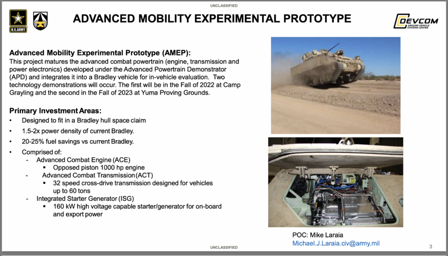
Are there any news about the Cummins /Achates ACE (advanced combat engine)? It has been quiet about its development from the companies for two years now ...
 
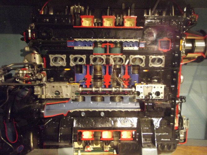
The Junkers Jumo two-stroke diesel aero-engines had two crankshafts geared together. The aircraft propeller was driven from the upper shaft and the engine accessories - the fuel pump, injectors and scavenging compressor - from the lower. About three quarters of the output power came from the top crankshaft. The Junkers engineers realised that scavenging could be improved by not having the pistons reach TDC together. The intake ports were under the lower piston and the exhaust ports under the upper. The engine was designed so that the lower crank lagged 11° behind the upper. The exhaust ports thus opened first, allowing much more efficient scavenging. The Jumos were the first and for a long time the only diesel aero-engines in service. They powered the Junkers 86; which visited British skies in 1941/42 in bomber and photo reconnaissance roles. The engine was not popular with aircrews because of slow throttle response and poor reliability. The aircraft performed much better with Swedish-built Bristol Pegasus engines.

Jumo.D.JPG

Cutaway Jumo in the Louman Museum in The Hague. I apologise for the picture quality but flash photography is not allowed and the lighting is less than optimum.
 
Are there any news about the Cummins /Achates ACE (advanced combat engine)? It has been quiet about its development from the companies for two years now ...
There were a spate of articles about it around August.
The focus seems to be putting it into the next M88 refit at this time, though I bet it will be pitched to a number of programs.
 
I was doing some checking on the enginehistory.org site. Junkers was the first company to build diesels for aircraft, with the MO-3 in 1913 (!) and the 500 hp FO-2 in 1916. I don't know if any of these flew, although the FO-2 was likely the grandparent of the 204.
 
I'm surprised no-one has mentioned the Napier Deltic; three banks of six cylinders (each with two pistons) arranged in a triangle, giving 1750Hp. The triangular arrangement meant each bank of cylinders had a crankshaft at each end but saved weight as there were only three crankshafts for three banks. It did need a supercharger (and compressed air starting) to work, and gave good service in the Dark class FPBs and, of course, the Deltic class Locomotives.

SRJ.
 
I'm surprised no-one has mentioned the Napier Deltic
You beat me to it - that is exactly what I was intending to post! One of the most interesting engines ever built IMO.
Napier's conceptual leap was the realisation that one of the crankshafts has to turn in the opposite direction to the other two for it to work. There are some good animations out there on the 'web, along with a Lego model.

SRJ.
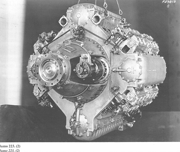
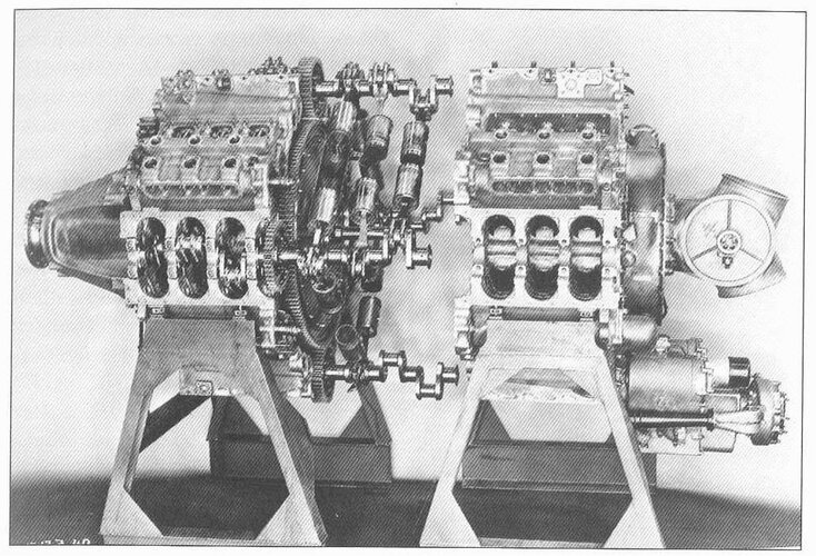
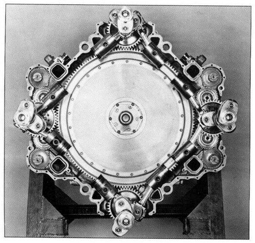
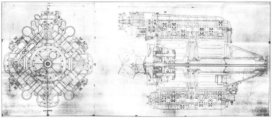
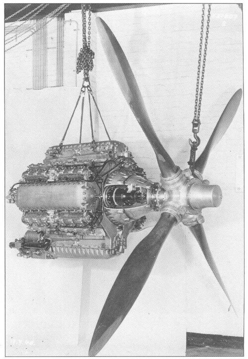
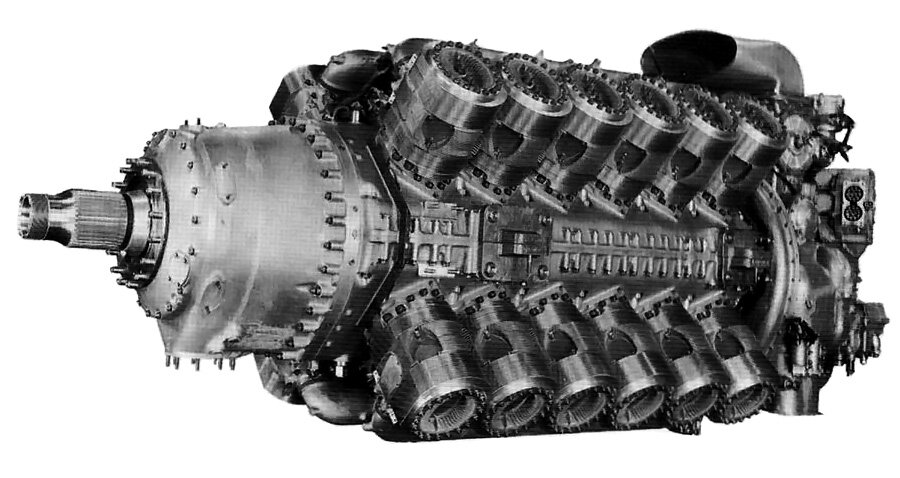
The Deltec was the result of Napier's experience with licensing of the Junkers opposed piston technology before WWII. The Deltec was interesting and actually made it into full production, but technically the Junkers Jumo 223 and 224 which used four crankshafts in a quadrilateral configuration were superior (for a number of reasons). The Junkers Jumo223/224 never made it into production and disappeared into Russia along with its designer after WWII.

Notice that all four crankshafts rotate in the same direction, it was destined for use in transports as was the WWII Roll Royce Pennine, an air cooled, X24, sleeve valve, spark ignition 4 stroke engine. The four large covers on the outside of the engine cover the crankshafts with the fuel injector pumps on each side of the horizontal crankshaft covers.

Both engines had 24 cylinders but the Junkers had 48 pistons and was a two stroke so a firing stroke every 15 degrees of rotation of the crankshafts. The Jumo 223/224 was an incredibly elegant design. The last photo is on the RR Pennine, a scaled up Exe, neither of which made it into production.

Bob
Ju-223.jpg JunkersJumo223exploded.jpg JunkersJumo223x-section-red.jpg JunkersJumo223drawing.jpg JunkersJumo223withprop.jpg rolls-royce-pennine.jpg
 
Last edited:
The July 2021 edition of ‘The Automobile’ mentions engines designed by the very versatile South African, Claude Hector May. He followed Karl Otto Keller (Doxford), Tranquillo Zerbi (Fiat) and others into opposed piston engines, proposing a wide range of sizes and actually running, according to the article, an 8-cylinder blown compression-ignition 2-stroke having 8 cylinders of 200x157mm bore and stroke and fan assisted scavenging. A displacement of ca. 40 litres is mentioned. On test the engine gave 3100 bhp at 2500 rpm. The potential customer was Brooke Marine of Lowestoft.


There seems to be some difficulty with this information. Eight cylinders, each containing a single piston, with dimensions of 200x157mm do indeed displace ca. 40 litres, 39458cc actually. But an opposed cylinder engine has two pistons per cylinder and this one would therefore displace 78917cc giving 39 hp/litre, which seems an unattractive result. It is an interesting bit of history nevertheless. Does anybody know more?
 
The spec says '8 cylinders of 200x157mm bore and stroke', not 8 pistons. So your doubling seems unwarranted. 157 is the combined stroke of the 2 pistons.
 
The spec says '8 cylinders of 200x157mm bore and stroke', not 8 pistons. So your doubling seems unwarranted. 157 is the combined stroke of the 2 pistons.
Bore and stroke of 200x78.5 seems to carry short stroke design a bit far?
 
200 x 78.5 doesn t make any sence at all, but even 200 x 157 would be quite silly. One of the bigest advantages of the opposed piston engine is the low heat loss during combustion because of the usually extremly long (combined) stroke in relation to the bore (about half of a conventional engine with a cylinder head). Why should anybody want to built a opposed piston engine with a short stroke design? It doesn't make sence and doesn't even help with breathing, since long stroke designs offer greater port sizes per volume.
 
Clearly 200x78.5 and 200x157are both nonsense but perhaps a writer in a classic car magazine was unaware of the convention that bore precedes stroke and got the tail on the front of the dog. 157x200 in 8 cylinders would displace very close to 31 litres, so 3100 bhp would be 100 hp/litre, which sounds just like the nice neat sort of result that the designers I used to know would go for. Just a thought?
 
Anyone thought to put several opposed piston engine blocks to make a spar….fuselage section? Who says it all has to be a lump? Drive electric systems…
 
If you spread an engine around like that, vibration problems will multiply. In multicylinder engines, the vibration of individual cylinders can cancel each other out, depending on the engine layout: straight-6 and V12 engines are especially good in this regard, single-cylinder engines are the worst. You're also multiplying the weight of the structure and the engine ancillaries.
 
But you want that strength. Phys.org takes more and more about batteries being the frames themselves. If not opposed piston…maybe in-lines. Looking at engines that can drop in booms. The radials could work with cylinders shot away….there is a lot of wisdom from yesteryear that has been beaten out of aviation by simple yet effective twinjets.

Today’s twinjets are like the crutch that was the Delta II…in that the good-enough became the enemy of the better.
 
why cant you stay on topic? What do batteries and Twinjets have to do with opposed piston engines???
 
Napier's interest in opposed-piston diesels began in the early 1930s when they licensed the Junkers Jumo technology. The Culverin was based on the Jumo 204, while the Cutlass was slightly smaller - presumably based on the Jumo 205. Although they did not enter production, they laid the groundwork for the Deltic.

Another variation was developed by Saurer, a Swiss industrial giant who bent the cylinders in the middle to create a rhombic drive with two crankshafts driving two cyliners in each bank. See the FLB engine discussion. Although originally another Diesel, they later converted it to run on petrol.
 
I'm surprised no-one has mentioned the Napier Deltic; three banks of six cylinders (each with two pistons) arranged in a triangle, giving 1750Hp. The triangular arrangement meant each bank of cylinders had a crankshaft at each end but saved weight as there were only three crankshafts for three banks. It did need a supercharger (and compressed air starting) to work, and gave good service in the Dark class FPBs and, of course, the Deltic class Locomotives.

SRJ.
Beat me to it! I think the deltics are really under appreciated. 50 years on I'm sure you could substantially improve efficiency through electronic control of injection and CFD optimised pistons and ports.
 
Anyone remember the Leyland L60? The Chieftains Achilles Heal, for the British Army to introduce an opposed piston engine than that memory will alert anyone to the dangers of introducing immature tech.
The tech wasn't immature as the UK industry was well able to build opposed diesels for rail, marine and road applications. It was probably asking too much of the engine to shift a 50 ton tank. The later Shir tank had a more conventional diesel.
 
I'm surprised no-one has mentioned the Napier Deltic; three banks of six cylinders (each with two pistons) arranged in a triangle, giving 1750Hp. The triangular arrangement meant each bank of cylinders had a crankshaft at each end but saved weight as there were only three crankshafts for three banks. It did need a supercharger (and compressed air starting) to work, and gave good service in the Dark class FPBs and, of course, the Deltic class Locomotives.

SRJ.

It needed a scavenging pump, as do all two-stroke engines. Compressed air starting isn't that uncommon on large or very large diesels.
 
It needed a scavenging pump, as do all two-stroke engines. Compressed air starting isn't that uncommon on large or very large diesels.
Is that an uncommon thing? Many engines have them. But not all two-strokes do, or at least they did not at one time.
 
Scavenging blowers are a typical two stroke item, four stroke engines can use blowers as well (for supercharging) but this is very uncommon in post war cars (there are some modern applications). Supercharging and scavening ist not the same.

In large two stroke engines, electrical driven turbochargers have replaced the scavening blowers completely
 
It needed a scavenging pump, as do all two-stroke engines. Compressed air starting isn't that uncommon on large or very large diesels.
Is that an uncommon thing? Many engines have them. But not all two-strokes do, or at least they did not at one time.

All current two-stroke engines have a scavenging pump*; I believe that all two-strokes require one, but there may have been two-strokes without a scavenging pump in the past.


----
* Most commonly, small two-strokes are crankcase scavenged, which means that the crankcase (and the bottoms of the pistons) are the scavenging pump.
 
It needed a scavenging pump, as do all two-stroke engines.
Is that an uncommon thing? Many engines have them. But not all two-strokes do, or at least they did not at one time.

All current two-stroke engines have a scavenging pump*; I believe that all two-strokes require one, but there may have been two-strokes without a scavenging pump in the past.

----
* Most commonly, small two-strokes are crankcase scavenged, which means that the crankcase (and the bottoms of the pistons) are the scavenging pump.

Really? Do you have a reference for that?

A common trick with two-strokes is, or was, to introduce the fuel-air mixture into the crank case. A channel is cut in the cylinder wall so that when the piston descends, it forces the mixture up through the channel and into the combustion chamber. In this design, oil mist in the crank case has to be avoided as it would contaminate the combustion mixture. There is thus nothing to scavenge and idea that this is a "scavenging pump" action is nonsense.

Lubrication of the crank bearings and cylinder walls may be achieved in either or both of two ways, by introducing oil channels direct to the bearing surfaces and/or by introducing an immiscible oil mist (typically castor oil) into the combustion mixture (typically by adding to the fuel in the tank; when the fuel evaporates, the oil becomes a mist). Waste oil may be gathered in a sump for recirculation via a plain old oil pump, or (especially if it is supplied constantly with the fuel) allowed to drain off as a total-loss system. It is a mistake to regard a simple oil circulation pump as a scavenging pump, as the ordinary pump circulates liquid, relies on the presence of an oil bath in a sump and is preceded only by an oil filter in the line, whereas a scavenging pump circulates a much greater volume of air-oil mixture and must be followed by a separator.

A scavenging pump is only needed in higher-performance engines (whether two- or four-stroke), and where the fuel-air mixture is fed direct to the combustion chamber via an intake port, valve and/or fuel injector (such as all Diesels). Here, oil may accumulate in the crank case and splash around. This is tolerated, even intentional as part of the distribution system, in some designs. But for higher-powered engines significant amounts may get thrown up under the pistons and upset the engine balance. Hence it has to be scavenged and in bigger engines, in order to reduce ducting, several pumps may be fitted for this purpose.

It may well be that all current opposed-piston designs come into this last category, but whether they are two- or four-stroke is irrelevant to the need for scavenging.
 
Last edited:
It needed a scavenging pump, as do all two-stroke engines.
Is that an uncommon thing? Many engines have them. But not all two-strokes do, or at least they did not at one time.

All current two-stroke engines have a scavenging pump*; I believe that all two-strokes require one, but there may have been two-strokes without a scavenging pump in the past.

----
* Most commonly, small two-strokes are crankcase scavenged, which means that the crankcase (and the bottoms of the pistons) are the scavenging pump.

Really? Do you have a reference for that?

A common trick with two-strokes is, or was, to introduce the fuel-air mixture into the crank case. A channel is cut in the cylinder wall so that when the piston descends, it forces the mixture up through the channel and into the combustion chamber. In this design, oil mist in the crank case has to be avoided as it would contaminate the combustion mixture. There is thus nothing to scavenge and idea that this is a "scavenging pump" action is nonsense.

Lubrication of the crank bearings and cylinder walls may be achieved in either or both of two ways, by introducing oil channels direct to the bearing surfaces and/or by introducing an immiscible oil mist (typically castor oil) into the combustion mixture (typically by adding to the fuel in the tank; when the fuel evaporates, the oil becomes a mist). Waste oil may be gathered in a sump for recirculation via a plain old oil pump, or (especially if it is supplied constantly with the fuel) allowed to drain off as a total-loss system. It is a mistake to regard a simple oil circulation pump as a scavenging pump, as the ordinary pump circulates liquid, relies on the presence of an oil bath in a sump and is preceded only by an oil filter in the line, whereas a scavenging pump circulates a much greater volume of air-oil mixture and must be followed by a separator.

A scavenging pump is only needed in higher-performance engines (whether two- or four-stroke), and where the fuel-air mixture is fed direct to the combustion chamber via an intake port, valve and/or fuel injector (such as all Diesels). Here, oil may accumulate in the crank case and splash around. This is tolerated, even intentional as part of the distribution system, in some designs. But for higher-powered engines significant amounts may get thrown up under the pistons and upset the engine balance. Hence it has to be scavenged and in bigger engines, in order to reduce ducting, several pumps may be fitted for this purpose.

It may well be that all current opposed-piston designs come into this last category, but whether they are two- or four-stroke is irrelevant to the need for scavenging.
References? Any book on internal combustion engine design. You could start with the classic (and somewhat dated) The Internal Combustion Engine in Theory and Practice, by Charles Fayette Taylor, or Internal Combustion Engine Fundamentals, by John Heywood.
 
@steelpillow
you didnt undestand the way simple two stroke engines with their crank case scavenging pumps are working. Any two stroke engine needs a device for the gas exchange, in most simple designs this is done by the piston underside, lubrication is just a side effect.

You could try out to fix a carburator directly to the scavanging port of a lawn mower engine without using the crankcase and you will find out, that it wan't run at all.
 
References? Any book on internal combustion engine design. You could start with the classic (and somewhat dated) The Internal Combustion Engine in Theory and Practice, by Charles Fayette Taylor, or Internal Combustion Engine Fundamentals, by John Heywood.

Can you quote a passage from that source which supports your use of the term "scavenging pump"?
 
Last edited:
quote: "A scavenging pump is only needed in higher-performance engines (whether two- or four-stroke), and where the fuel-air mixture is fed direct to the combustion chamber via an intake port, valve and/or fuel injector (such as all Diesels). Here, oil may accumulate in the crank case and splash around. This is tolerated, even intentional as part of the distribution system, in some designs."

A scavanging pump is allways needed, the crankcase with the undeside pf the Piston can be used as scavanging pump, but gas exchange will allways need another force from outside the cylinder.
 
References? Any book on internal combustion engine design. You could start with the classic (and somewhat dated) The Internal Combustion Engine in Theory and Practice, by Charles Fayette Taylor, or Internal Combustion Engine Fundamentals, by John Heywood.

Can you quote a passage from that source which supports your use of the term "scavenging pump"?


you didnt undestand the way simple two stroke engines with their crank case scavenging pumps are working. Any two stroke engine needs a device for the gas exchange, in most simple designs this is done by the piston underside, lubrication is just a side effect.

You could try out to fix a carburator directly to the scavanging port of a lawn mower engine without using the crankcase and you will find out, that it wan't run at all.

What part of "A common trick with two-strokes is, or was, to introduce the fuel-air mixture into the crank case. A channel is cut in the cylinder wall so that when the piston descends, it forces the mixture up through the channel and into the combustion chamber. " demonstrates the failure of understanding here?
(And can you quote a source which supports your use of the term "scavenging pump"?)
I would use scavenge pump as a more relevant term for inverted four-strokes that need to suck oil out of inverted cylinder heads, to prevent hydrostatic locking.
 
A scavanging pump is allways needed, the crankcase with the undeside pf the Piston can be used as scavanging pump, but gas exchange will allways need another force from outside the cylinder.

I once had a little Cox BabeBee .049 two-stroke glow plug engine. It had a port on either side, and each acted as both intake and exhaust port. Gas exchange was accomplished via the dynamics of the cylinder gases as the piston rose and fell. The entire engine had just two moving parts, the piston and the crankshaft. My dad had an equally valveless two-stroke mower, a Hayter but I do not know who made the engine. Air was sucked in through the intake port via a carburettor and combustion gases expelled via the exhaust port through a silencer. Gas exchange was again induced by the cylinder gas dynamics, with the help of a slipper piston crown. No scavenging pump, no force of any description outside the cylinder was present on either engine. So please stop repeating unsupported claims that fly in the face of the evidence and either quote us supporting sources or leave off altogether.

It is quite simple. Two strokes use either crankcase scavenging (nearly all small two stroke enginges) where a positive pressure is produced by the down running piston and where you can only use loss lubrication (mixed petrol-oil), or they use a supercharger device like a roots blower or centrifugal compressor (usually in larger (diesel) two strokes).
 
Last edited:
GDLS AbramsX concept vehicle is currently being shown off at AUSA, and it's driving around on it's own power using an ACE powerpack, thus confirming that one scaled to MBT size currently exists.
 
A scavanging pump is allways needed, the crankcase with the undeside pf the Piston can be used as scavanging pump, but gas exchange will allways need another force from outside the cylinder.

I once had a little Cox BabeBee .049 two-stroke glow plug engine. It had a port on either side, and each acted as both intake and exhaust port. Gas exchange was accomplished via the dynamics of the cylinder gases as the piston rose and fell. The entire engine had just two moving parts, the piston and the crankshaft. My dad had an equally valveless two-stroke mower, a Hayter but I do not know who made the engine. Air was sucked in through the intake port via a carburettor and combustion gases expelled via the exhaust port through a silencer. Gas exchange was again induced by the cylinder gas dynamics, with the help of a slipper piston crown. No scavenging pump, no force of any description outside the cylinder was present on either engine. So please stop repeating unsupported claims that fly in the face of the evidence and either quote us supporting sources or leave off altogether.

I didn"t read this posting until tody, so now a delayed answer.

Here we learn the troth about the Cox engine, it has a reed valve intake system, and scavaging port in the cylinders:

The Cox engine disassembled with the Reed valve:

View: https://www.youtube.com/watch?v=3ALEbQoQdZ4&ab_channel=David%27sStuff


The Cox cylinders with the scavenging ports:


So we see, it works like a very conventional two stroke, just the parts look a little unfamiliar. The same is true for the lawn mover engine, it is just a missinterpretation.
 
Last edited:

Similar threads

Please donate to support the forum.

Back
Top Bottom