There is a theory that there was a concept to equip the Shinden with a jet engine and call it "Shinden Kai" (J7W2). The basis for this theory is an contribution written by Kunitake Kiyohara, former deputy chief of the 1st Design Division of the Kyushu Airplane Design Department, in an aviation magazine.

In his contribution, Kiyohara wrote, "On June 5, 1944, at the 'Shinden' Project Request Study Group held at the Kugisho, or as an instruction afterwards, a member of the Kugisho's engine staff said as indication to me, "Proceed with the design of modified Shinden using a jet engine. The jet engine to be installed in the modified Shinden will have a ground static thrust of 900 kg, which is equivalent to almost 3,000 HP, and the expected speed will be about 420 kt (780 km/h). However, this modified Shinden requires a take-off auxiliary rocket, which we want to treat as an overload condition."

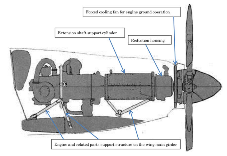
In his contribution, Kiyohara also wrote, "I thought that the jet engine to be installed in the improved Shinden model would be a Ne-130 jet engine that was being prototyped at the Ishikawajima Shibaura turbine, and I thought that the dogfight era was finally over. Considering the layout of the Shinden's engine, I thought it would not be so difficult to replace it with a jet engine. I was excited by this plan and I wanted to realize as soon as possible. In the end, this plan did not come to fruition, but the twin-engine jet attack aircraft "Kikka" designed by Nakajima Aircraft was prototyped by Kyushu Aircraft, and the war ended when the first aircraft was almost completed.

However, no other specific records have been found of jet engine installed modified Shinden In addition, Mitsuo Nishimura, who served as the chief of Shinden's power outfitting team, also admitted that there was a plan for jet Shinden, but also testified that "no concrete progress had been made" toward its realization. The progress of the development of the Ne-130, a prototype jet engine that was scheduled to be installed at the time, was only at the stage of full-scale testing near the end of the war, and it was not in a situation where it could actually be operated.

The predecessor of the Ne-130, the Ne-20, had a variety of fatal flaws, which shortened its endurance life to only 15 hours at full power. This defect was exposed even during the test flight of Kikka, which was being developed in parallel with Shinden, and it is said that it was not going to be solved. This defect occurred not only in the Ne-20 but also in the Ne-130 under development, and of course it was not in a situation where it could be installed on the Shinden.

Furthermore, at the end of the war, Japan was almost depleted of rare metals (nickel, chromium, etc.) for making heat-resistant metals that were indispensable for jet engines, and the development of alternative metals with high heat resistance due to a lack of resources for exhaust turbines was a major problem. Therefore, even if a prototype jet engine was completed, mass production would have been almost impossible.
 
It's correct that "jet Shinden" existed only as an idea among the design team. Furthermore Ne-130 did not exist even as an idea in June 1944. The work on Ne-130 would not begin until the basic plan meeting on 13 December 1944. Ne-20 started development shortly after on 25 December 1944.

In June 1944, Shinden team was probably instructed to consider the possibility of using a jet engine of generic specifications, when one would come to fruition. That is, no specific work was actually done to this end. It makes some sense because this is roughly the time period where the Navy Aviation staff became interested in the jet engine, because it was reported that it was effective in Germany.
 
If the P-39 could rear-mount a front propeller then it surprises me the reverse was not tried in something like this. It was well known that rotaries overheated in a rear mount.
 
If the P-39 could rear-mount a front propeller then it surprises me the reverse was not tried in something like this. It was well known that rotaries overheated in a rear mount.

I may misunderstand the question. Mounting the engine up front would defeat the purpose of this design. Rear mount allows significant reduction of drag by streamlining the fuselage, and the installation of extremely heavy armament to easily shoot down strategic bombers. But it is correct that there were unresolved difficulties in achieving adequate cooling.
 
If the P-39 could rear-mount a front propeller then it surprises me the reverse was not tried in something like this. It was well known that rotaries overheated in a rear mount.
Dear Madrat,
I get the impression that English is not your first language.

Long drive shafts suffered torsional vibration problems especially when driven by jerky piston engines. Long drive-shafts remained problematic until smooth-turbo-shaft jets were introduced during the 1950s. Hence the only successful WW2 airplanes were Bell’s P-39 Airacobra and P-63 Kingcobra. They mounted engines behind the pilot to make room for 37mm auto-cannons firing through the tractor propeller.
Shinden and most twin-boom pushers needed drive-shafts in order to mount the heavy engine near the center-of-gravity, but still mount the prop far enough aft to streamline the rear end of the engine nacelle/fuselage.

Both Shinden and Curtiss’ Ascender would have enjoyed better stability and control with C.ofG.s even farther forward than OTL.

To be more precise: air-cooled RADIAL engines suffered cooling problems when buried deep in fuselages. All air-cooled engines suffer cooling problems when buried too deep hence the extra cooling fan on the rear engine of Cessna’s 337 Skymaster.

OTOH air-cooled rotary engines were limited to WW1. Since the entire crankcase and all the cylinders rotated around the fixed crankshaft, they cooled great at the low air speeds (e.g. 100 knots) of WW1. Rotary engines were only successful when installed without cowlings (Airco pusher) and or 3/4 cowlings (e.g. Nieuport 17).
 
Last edited:
If the P-39 could rear-mount a front propeller then it surprises me the reverse was not tried in something like this. It was well known that rotaries overheated in a rear mount.
There's a drawing of the engine layout for the Shinden, it has a driveshaft to the prop at the rear. But the Shinden would have been much better served with a liquid cooled V engine, which would have required a shorter driveshaft to the prop.
 
Dear riggerrob,

You realized right away I meant radial. Clearly, I am not ESL. Radials, like rotaries, were poor for rear mounts for the same reason. Getting clean air evenly across hot spots on the circular layout of pistons was not possible. Liquid cooled V engine was the obvious solution.
 
I assume that the fan was spinning much faster than the prop RPM?
I only found following Raiden data.
14shi interceptor (J2M1)
Engine:Kasei Type 13
Maximum speed 574km/h
Engine revolution: 2,350rpm
Reduction ratio (Propeller) 0.684
Speed increase ratio (cooling fan) 1.000
Peripheral speed at propeller tip: 269 m/sec (969 km/h)
Peripheral speed at the tip of the cooling fan: 62 m/sec (227 km/h)

Raiden Type 11 (J2M2)
Engine:Kasei Type 23
Maximum speed 596km/h
Engine revolution: 2,500rpm
Reduction ratio (propeller) 0.500
Speed Increase Ratio (Cooling Fan) 3.180
Peripheral speed at propeller tip: 216 m/sec (777 km/h)
Peripheral speed at the tip of the cooling fan: 156 m/sec (562 km/h)
 
The main body of the engine and the reduction housing located at the rear end of the fuselage are connected by an extension shaft with a length of 900 mm.
In order to prevent vibration caused by the extension shaft, the three girders of the main wing were installed on the pillars that support the engine, the extension shaft support cylinder, and the reduction housing.
It is a unique support structure for the engine and related parts in which the main wing supports these weights.
This support structure was designed to prevent vibration and seizure due to deflection of the extension shaft.
 

Attachments

  • engine support structure.jpg
    engine support structure.jpg
    236.3 KB · Views: 130
Presumably, the thrust of the propeller is not applied to the extension shaft to prevent vibration and seizure, but to the extension shaft support cylinder, and then to the engine body and finally to the main wing.
If so, how about Senden?
XP-55 did not use extension shaft.
 

Attachments

  • Curtiss-XP-55-cutaway-drawing.jpg
    Curtiss-XP-55-cutaway-drawing.jpg
    57.2 KB · Views: 144
Last edited:
Presumably, the thrust of the propeller is not applied to the extension shaft to prevent vibration and seizure, but to the extension shaft support cylinder, and then to the engine body and finally to the main wing.
If so, how about Senden?
XP-55 did not use extension shaft.
Yes, Curtiss Ascender did not use an extension shaft, but it also suffered handling problems because the center-of-gravity was too far aft.
 
Last edited:
Hi! Shinden restration model.
 

Attachments

  • 1f9ffd16-1bfd-42fa-8c6d-cd9fc6cd041e.jpg
    1f9ffd16-1bfd-42fa-8c6d-cd9fc6cd041e.jpg
    241.1 KB · Views: 89
  • e4e7d683-ae9e-4511-a095-2028ed00f101.jpg
    e4e7d683-ae9e-4511-a095-2028ed00f101.jpg
    258.1 KB · Views: 84
  • e97f9e4a-d7ee-4140-8562-642339f82d60.jpg
    e97f9e4a-d7ee-4140-8562-642339f82d60.jpg
    209.7 KB · Views: 80
  • f85bbc85-65fe-4146-8631-9f277e0cac6c.jpg
    f85bbc85-65fe-4146-8631-9f277e0cac6c.jpg
    277.7 KB · Views: 76
  • 8735d76a-5aab-4134-85a8-7833e847f5e3.jpg
    8735d76a-5aab-4134-85a8-7833e847f5e3.jpg
    726.9 KB · Views: 93

Attachments

  • kyushu-j7w1-shinden-13-scaled.jpg
    kyushu-j7w1-shinden-13-scaled.jpg
    1.4 MB · Views: 70
  • kyushu-j7w1-shinden-06.jpg
    kyushu-j7w1-shinden-06.jpg
    293.1 KB · Views: 66
  • kyushu-j7w1-shinden-09.jpg
    kyushu-j7w1-shinden-09.jpg
    365.1 KB · Views: 52
  • Photo2.jpg
    Photo2.jpg
    43.3 KB · Views: 50
  • Photo3.jpg
    Photo3.jpg
    37.5 KB · Views: 52
  • Photo4.jpg
    Photo4.jpg
    32.6 KB · Views: 56
  • Photo12.jpg
    Photo12.jpg
    32.1 KB · Views: 84
Last edited:
Dear riggerrob,

You realized right away I meant radial. Clearly, I am not ESL. Radials, like rotaries, were poor for rear mounts for the same reason. Getting clean air evenly across hot spots on the circular layout of pistons was not possible. Liquid cooled V engine was the obvious solution.

Yes, I recognized that you were referring to World War 2, fixed radial engines.
One of the reason that World War 1 rotary engines spun was to help cooling at sub-100 mph flying speeds. Note how the bottom third of many rotary cowlings was missing (e.g. Nieuport 17) to admit more cooling air. The upper cowling was more about reducing the amount of castor oil flung into the pilot's face.
Hah! Hah!

See the Shinden forced air fan in post 253.
Most pusher-mounted, air-cooled engines need to add a fan to ensure proper cooling while in the ground. See Molt Taylor's Coot pusher amphibian and Cessna 337 rear engine.
 
Hi! Shinden restration model.
When I saw that, it’s sad how the Smithsonian isn’t doing anything with the one (the only surviving example) they have. I sometimes wonder how they prioritize which aircraft gets restored next.
 
When I saw that, it’s sad how the Smithsonian isn’t doing anything with the one (the only surviving example) they have. I sometimes wonder how they prioritize which aircraft gets restored next.
Budget and relevance. are strong factors. No disrespect to the Shinden, there are so many other airframes in their possession to choose from. Maybe someone in Japan can tackle the restoration in a manner like the Do335 and Horten flying wings were restored.

Enjoy the Day! Mark
 
A person in charge of an exhibition hall in Japan planned to bring Shinden home, but when he informed the NASM of the plan, it was turned down. It is unclear at all what the NASM wants to do with Shinden.
 
A person in charge of an exhibition hall in Japan planned to bring Shinden home, but when he informed the NASM of the plan, it was turned down. It is unclear at all what the NASM wants to do with Shinden.
Not surprised. I can think of a few possible reasons why aircraft like the Shinden and even the Horton Ho 229 have not been restored. The least of which the NASM probably feels that no one but them can restore an aircraft better.
 
Fascinating thread with a lot of good info posted about this unique aircraft, especially by @blackkite.

I know that the J7W1 Shinden was designed as an interceptor, but it's still often depicted in popular culture as being quite maneuverable and able to do tight turns. However, I am sceptical to this since it had a quite high span- and wing loading, and not a very good power loading either. In addition, the "pyramidal" wing twist scheme on each wing would have resulted in a poor Oswald factor, thus further increasing the induced drag in turns.

In addition, it's not uncommon that people attribute canard aircraft good turn capabilities solely based on the fact that the canard provides an "up" force as opposed to the "down" force on the tail of a more conventional aircraft. However, this effect is rather small compared to the lift of the main wing, which on a stable canard configuration is unfortunately quite low due to the need for the canard to stall before the main wing.

While I've seen estimates on speed and climb, are there any original Japanese estimates or calculations of the Shinden's performance when it comes to turns?
The canard formula had many advantages for the design of fighters; the armament could be grouped around the nose without any hindrance by either the engine or the propeller and it was very easily accessible for maintenance, ground visibility was considerably improved and it was easier to install a tricycle type undercarriage.

The nose foreplanes had been found to serve the purpose of improving take-off performance and low speed control.

The engine, located behind the pilot, acted as protection against the rear impacts and, in the event of a fire, flames did not go to the cockpit as used to happen with the classical designs. Besides, being joined to the main spar meant less weight and stronger structural sturdiness.

In combat, an enemy pilot not familiar with the new configuration could easily mistake the direction to which the canard fighter moved during the deflection aiming. Same tactic is used by some tropical fishes that have a spot in the shape of a false eye near the tail to confuse their predators.

Only two inconveniencies marred all the advantages: the difficulty to refrigerate the engine and the baling out, due to the position of the pusher airscrews. At a time when ejector seats did not yet exist, the solution was to install an explosive device to detach the propeller in case of emergency.

Early in 1939 the Italians built the Ambrosini S.S.4 a canard prototype fighter powered by one 960 hp Isotta Fraschini Asso XI RC.40 engine. The airplane was destroyed in 1941 due to a problem of vibration of the engine mount and the project was cancelled.

On 22 June 1940 the USAAC signed a contract for preliminary development of the Curtiss CW-24 and construction of a wind tunnel model, under the designation XP-55.

Such a radical configuration required the construction of the CW-24B, a flying testbed to prove the design viability.

On 21 December 1941 the CW-24B made its first flight, at Muroc Dry Lake test center, powered by a 275 hp Menasco C-6S-5 engine.

Despite the strong security measures, intelligence services of the IJN obtained enough information about the project to believe that it was the successor of the Curtiss P-40 fighter. Early in 1943 Lieutenant Commander Masaoki Tsuruno, of the First Naval Air Technical Arsenal, proposed the construction of the canard fighter 18-shi-Otsu J7W Shinden based on the information obtained on the XP-55.

In fact, the definitive Curtiss XP-55 version was not selected by USAAC for production and only three prototypes were built, two of which were destroyed in accidents.

On 10 July 1942 the USAAF ordered three prototypes, the 42-78845 flew on 13 July 1943 powered by one 1,425 Allison V-1710-95, V-12, liquid-cooled engine, with mechanical supercharger, driving a three-bladed (jettisonable) pusher airscrew.

The aircraft was fitted with laminar-flow swept wings angled back 45 degrees and tricycle undercarriage.

USAAF was unimpressed with the 377 mph top speed reached with the Allison engine versus the 507 mph promised with the X-1800 cancelled in October 1940.

The first prototype showed excessive take off run, dangerous stall behaviour, poor longitudinal stability, low-speed handling problems and engine overheating.

On 15 November 1943 the plane was lost, in an inverted spin, when the engine failed.

The second prototype 42-78846 flew on 9 January 1944 suffering from ‘no-warning before stalling’ phenomena. To improve the stall characteristics the nose elevator and the aileron tabs were modified.

The third prototype 42-78847 was flown on 25 April 1944, fitted with wing extensions and modified nose elevator and armed with four 0.50 cal nose mounted machine guns.

On 27 May 1945 the aircraft crashed when the pilot attempted a barrel roll.

Americans were not lucky with the Curtiss XP-55, after four years of flight testing they have not achieved an airplane sufficiently stable to take part in combat operations.

Although it was less sensible to the compressibility buffeting than conventional airplanes, thanks to a NACA 0015 type wing profile, it was also too heavy and slower than the P-47 and P-51 in service.
 
Thank you for summing up the US experience with the XP-55 Ascender. I'm familiar with this but it may be helpful for others in this thread to get a better understanding of the problems related to stable canard designs, other than the J7W1 Shinden.

And while I agree with many of the advantages you list, I'm not quite on-board with this:

"The nose foreplanes had been found to serve the purpose of improving take-off performance and low speed control."

Because the take-off and landing performance was actually poor due to the canard's problem to generate a high trimmable maximum lift coefficient (Clmax) on aircraft level when landing, and to generate lift at take-off by rotating to a decent angle of attack, due to the risk of prop strike. This (the low Clmax) is due to two factors: The first being that the canard has to stall before the main wing (handling requirement) which means that the main wing never gets close to it's full lift potential. The second is that trailing edge flaps are the single most powerful tool to get a high Clmax, and that while on conventional tractor aircraft, this lift is generated close to the CG and thus easy to trim out, on a canard the CG is much further forward, and the flaps moment of arm is longer meaning that the canard will have to generate a lot of lift to counter this. However, to get decent stall characteristics, the canard is already highly loaded even without flaps, and is thus poorly equipped to carry this extra load. Finally, both the Shinden and Ascender did not have the possibility to generate a decent angle of attack at take-off and landing, which combined with the low trimmable Clmax actually led to high take-off and landing speeds compared to conventional tractor configurations with a similar wing area.

As I recall it, the J7W1 Shinden's CG was located at 14% MAC which is quite far forward (circa 25-30% on conventional tractor planes) and AFAIK the prototype aircraft could in test flights barely hold up the nose in the climb, and the wing's trailing edge flap deflection had to be limited to only 30 deg at landing, both factors indicating that there was not that much pitch authority left at all for the low speed handling.
 
The canard formula had many advantages for the design of fighters; the armament could be grouped around the nose without any hindrance by either the engine or the propeller and it was very easily accessible for maintenance, ground visibility was considerably improved and it was easier to install a tricycle type undercarriage.

The nose foreplanes had been found to serve the purpose of improving take-off performance and low speed control.

The engine, located behind the pilot, acted as protection against the rear impacts and, in the event of a fire, flames did not go to the cockpit as used to happen with the classical designs. Besides, being joined to the main spar meant less weight and stronger structural sturdiness.

In combat, an enemy pilot not familiar with the new configuration could easily mistake the direction to which the canard fighter moved during the deflection aiming. Same tactic is used by some tropical fishes that have a spot in the shape of a false eye near the tail to confuse their predators.

Only two inconveniencies marred all the advantages: the difficulty to refrigerate the engine and the baling out, due to the position of the pusher airscrews. At a time when ejector seats did not yet exist, the solution was to install an explosive device to detach the propeller in case of emergency.

Early in 1939 the Italians built the Ambrosini S.S.4 a canard prototype fighter powered by one 960 hp Isotta Fraschini Asso XI RC.40 engine. The airplane was destroyed in 1941 due to a problem of vibration of the engine mount and the project was cancelled.

On 22 June 1940 the USAAC signed a contract for preliminary development of the Curtiss CW-24 and construction of a wind tunnel model, under the designation XP-55.

Such a radical configuration required the construction of the CW-24B, a flying testbed to prove the design viability.

On 21 December 1941 the CW-24B made its first flight, at Muroc Dry Lake test center, powered by a 275 hp Menasco C-6S-5 engine.

Despite the strong security measures, intelligence services of the IJN obtained enough information about the project to believe that it was the successor of the Curtiss P-40 fighter. Early in 1943 Lieutenant Commander Masaoki Tsuruno, of the First Naval Air Technical Arsenal, proposed the construction of the canard fighter 18-shi-Otsu J7W Shinden based on the information obtained on the XP-55.

In fact, the definitive Curtiss XP-55 version was not selected by USAAC for production and only three prototypes were built, two of which were destroyed in accidents.

On 10 July 1942 the USAAF ordered three prototypes, the 42-78845 flew on 13 July 1943 powered by one 1,425 Allison V-1710-95, V-12, liquid-cooled engine, with mechanical supercharger, driving a three-bladed (jettisonable) pusher airscrew.

The aircraft was fitted with laminar-flow swept wings angled back 45 degrees and tricycle undercarriage.

USAAF was unimpressed with the 377 mph top speed reached with the Allison engine versus the 507 mph promised with the X-1800 cancelled in October 1940.

The first prototype showed excessive take off run, dangerous stall behaviour, poor longitudinal stability, low-speed handling problems and engine overheating.

On 15 November 1943 the plane was lost, in an inverted spin, when the engine failed.

The second prototype 42-78846 flew on 9 January 1944 suffering from ‘no-warning before stalling’ phenomena. To improve the stall characteristics the nose elevator and the aileron tabs were modified.

The third prototype 42-78847 was flown on 25 April 1944, fitted with wing extensions and modified nose elevator and armed with four 0.50 cal nose mounted machine guns.

On 27 May 1945 the aircraft crashed when the pilot attempted a barrel roll.

Americans were not lucky with the Curtiss XP-55, after four years of flight testing they have not achieved an airplane sufficiently stable to take part in combat operations.

Although it was less sensible to the compressibility buffeting than conventional airplanes, thanks to a NACA 0015 type wing profile, it was also too heavy and slower than the P-47 and P-51 in service.

Instead of listing all these textbook passages it should nevertheless make one wonder why no canard plane could compete with a conventional configuration during and after WW2. The first and only non-flybywire canard aircraft which was serially produced was the Saab Viggen.
 
Last edited:
Instead of listing all these textbook passages it should nevertheless make one wonder why no canard plane could compete with a conventional configuration during and after WW2. The first and only non-flybywire canard aircraft which was serially produced was the Saab Viggen.
If you don't like my explanation, try your best

The first canard to fly successfully was the MiG-8

 
Last edited:
I don’t think anyone here is denying that a canard aircraft can be made of fly.

It's just that the question that really needs to be asked is if it’s a good idea to build a propeller powered canard type of aircraft at all, as in are they better than conventional tractor type aircraft?

Below is a figure from NASA paper 2382, where they ran a full sized Burt Rutan VariEze in one of NASA’s full scale wind tunnels.

Varieze cl alfa from NASA 2382 paper.jpg

Looking at this figure, proponent of canards may say: Yeah! That’s what I’m talking about! When the lift of the canard and main wing are combined, we get a Clmax of 1.7 at circa 22 degrees angle of attack! That’s way better than on conventional airplanes!

However, if we read the fine print in that NASA report, the reference area used to derive the impressive Clmax figure of 1.7 is based on the exposed, and not (as per aerodynamic convention) the total wing area.

On a conventional tractor aircraft, the Clmax using this total wing reference area is usually around 1.35. But using the same principle on the VariEze’s figure of 1.7, this drops to 1.32.

Well you may say, that’s not a big difference is it? 1.35 versus 1.32?

But here is the catch: Look at the VariEze’s lift slope figure above again, and you can see that you can’t take the VariEze to its full potential at 22 deg aoa, since the canard stalls already at around 15 deg aoa.

Now if we read of the Clmax for the complete aircraft there, at 15 deg aoa, when the nose drops due to the canard stalling, it’s 1.4, and which I suspect is the number Burt Rutan would like us to use. However, if we instead compare apples to apples, and use the same total reference wing area for both, then the 1.4 figure for the VariEze’s Clmax drops to 1.09, which then when compared to tractor aircraft’s typical 1.35 hardly comes off as impressive.
 
But here is the catch: Look at the VariEze’s lift slope figure above again, and you can see that you can’t take the VariEze to its full potential at 22 deg aoa, since the canard stalls already at around 15 deg aoa.
You can build it to stall at 22degAoA. IIRC my airframe instructor did.
 
You can build it to stall at 22degAoA. IIRC my airframe instructor did.

Well by moving the CG far enough back you could probably do that, but in the NASA report they stayed within the approved CG limits of the design and IIRC then they got a result corresponding to circa 1.17 in Clmax on aircraft level (max rear CG position) so still far below what a tractor can do.

However, if you take the CG even further back you would probably get enough control authority from the canard to take the VariEze to main wing stall as well, but that could land you into a deep stall since you could get a violent pitch up due to the now lowly loaded canard.
yes, the risk of a Deep Stall is horrifying.
 
Some RC model fly very well.

Yes, I’ve seen some videos in which it flies well, but given differences in Reynolds number, power to weight ratios, inertia distributions between models and real aircraft it is difficult to draw conclusion from watching those how the real aircraft would have behaved.

But for sure, some models fly nice and look great like this one!


But this was a sad story: This model looked absolutely fabulous. Too bad it crashed.....

 
About the J7W1 Shinden's control system:

I have seen some claim that the Shinden used its ailerons as elevons as well, i.e. that they were coupled to the elevator on the canard for augmented pitch control but I have not seen any evidence of this?

To me it looks like pitch control is only done with the flaps on the canard and that these function as elevator. In addition, if the pilot moves the control stick fore and aft, will he move both of the tandem mounted flaps on the canard, or just the rear one?

In addition, it seems that when the split flaps on the trailing edge of the main wing are lowered, the canard flaps and the slat on the leading edge of the canard are activated, so that the slat is moved forward, and the flaps are lowered as well?

So here I'm assuming that the movement of the canard flap is the sum of the pitch control input from the control stick and whatever angle is caused by the lowering of the trailing edge flaps and that these are overlayed?

Or is the trailing edge spilt flap on the main wing only coupled to the inner canard flap, and the elevator only operates the most rearward canard flap?
It's possible but complex to arrange.
 
After a bit of digging, as far as I can tell the J7W1 Shinden's controls work like this: The control in pitch is done solely by moving the aft of the two "flaps" in tandem on the canard surface. The flap closest to the canard's main surface and its slat on the nose are coupled to the trailing edge flaps on the main wing and only deploy when these are lowered.
 
I have heard of a situation I can only partially recall at 'flap reversal' in some aerodynamic conditions. It looks like this could have happened in the 'bank' manouvre.

This is another one I would like to see as a flying replica but then I would say that.
 
Before building the J7W1 prototype, its control system was tested with gliders and the results were satisfactory.

To meet the IJN requirements of 1943, (18-shi-Otsu non-official specification) calling for a land-based, high-performance interceptor able to counter the new Allied fighters, Nakajima proposed the twin engine J5N1 Tenrai and Kawasaki the J6K1 Jinpu. Early in 1943 Lieutenant Commander Masaoki Tsuruno, of the First Naval Air Technical Arsenal, proposed the construction of an 18-shi-Otsu ‘canard’ fighter based on the information obtained on the XP-55.

The Kaigun Koku Hombu ordered the firm Chigasaki Seizo K.K. the construction of three wooden experimental gliders MXY6, with ‘canard’ lifting surfaces, to prove the feasibility of the concept. Glider tests, towed by one Nakajima B5N bomber, began at Yokosuka in the fall of 1943, demonstrating good flight characteristics. One of the prototypes was finally fitted with a 22 hp Nihon Semi Ha-90/11 four-cylinder-boxer, air-cooled engine, driving a two-bladed wooden airscrew from a Kugisho MXY4 anti-aircraft target.

In 1945 the MXY6 was proposed to the IJN as a prototype suicide plane, but the project was not carried out because of the priority given to the construction of the Showa Toka bomber.

MXY6 3rd prototype technical data

Wingspan: 9.14 m, length: 7.3 m, height: 2.95 m, wing area: 17 sqm, max weight: 500 kg, max speed: 320 kph.


After a promising MXY6 tests, the Kaigun Koku Hombu ordered the Kyushu Hikoki K.K. (Watanabe Tekkosho) to design a high-performance ‘canard’ interceptor. One 1/6 scale wind tunnel model was tested by September 1944. Construction of the X-18/J7W1 prototype, equipped with laminar flow wings with maximum thickness located 45 per cent chord, had already begun on June 4 and was completed in April 1945. The engine selected by the IJN was a 2,130 hp Mitsubishi MK9D (Ha-43-42) radial engine, (without the torque converter of the Ha-43-21) with two speed mechanical first stage and Vulkan coupling second stage, Methanol injection and forced cooling fan. The pusher propeller was one Sumitomo/VDM six-bladed, constant-speed with 3.4 m of diameter.

It was decided that the production version would be armed with four Type 5, 30 mm cannon with 60 rpg. and two Type 100, 7.92 machine guns. Pilot protection would consist of one 70 mm thick armoured glass windshield and one anti-bullet board armour plate with 16 mm thickness. The first flight of the prototype took place on 3 August 1945. During testing the plane suffered cooling problems while running the engine still on the ground, the powerful MK9D generated a great deal of torque, and the airplane pulled hard starboard at take-off. Small retractable wheels were added to the base of each fin to prevent tail damage upon landing. In flight the prototype showed strong vibrations in the propeller and its extended drive shaft. The IJN expected a production of 150 aircraft per month during 1946, built by Kyushu and Nakajima, but the construction of the second prototype was not completed.
 

Attachments

  • 095.jpg
    095.jpg
    1.2 MB · Views: 26
Interesting details both about the MXY6 and a nice drawing too, so thanks for sharing those.

Also interesting to learn more about their systematic approach to canard designing with wind tunnel testing, first glider, then powered sub-scale prototyping.

Too bad they did not get to do more than the three test flights with the J7W1Shinden prototype though. As I recall it, they basically only got to do some take-offs, climb, and landing tests, so a lot of the flight envelope remained unexplored as I understand it.

Would have been nice to get some flight test data on top speed since when reverse engineering both the Shinden and XP-55 from suggested numbers, it looks like they both had remarkably low Cdo.

In addition, things like the J7W1 Shinden’s behavior in accelerated stalls during tight turns, sustained turn rates, stall speed (i.e. trimmed Clmax), and roll and turn performance would have been nice to see.

About the torque: At first I wondered why they were complaining so much about it, but if you think about it, on a tractor, the rotating slipstream induces angles of attack on the wings and tail section which counteracts the torque the pilot experiences while on a pusher, you’re left to counter the full force of the torque with the ailerons.

In addition, the short moment of arm for the rudders on Shinden don’t help either when trying not to veer of the runway, so I’m not surprised if they had to be even more careful with applying power at take-offs compared to typical tractor designs.
 

Similar threads

Please donate to support the forum.

Back
Top Bottom