You are using an out of date browser. It may not display this or other websites correctly.
You should upgrade or use an alternative browser.
You should upgrade or use an alternative browser.
Iowa and Alaska Class Conversion Projects
- Thread starter Triton
- Start date
- Joined
- 16 April 2008
- Messages
- 9,600
- Reaction score
- 14,470
I vaguely remember 5"/54 mark 16 guns aka the Montana/Midway guns but I was not sure as these guns were quite old (40-50 years) by that time
Just so. The Midways had Mark 16 guns in the single Mark 39 turret. It looks like 50 were initially installed in the Midways, and steadily removed over time. They were all gone by 1980 and I really doubt many got saved from scrapping (or being parted out to the Japanese). About 15 of the ex-Midway guns went to Japan for their Akizuki-class and Murasame-class destroyers in the late 1950s and seem to have survived until the late 1980s/early 1990s (which is a lot longer than I expected, to be honest).
The Montanas were supposed to have a twin turret called the Mark 41, but I don't think that was ever built.
Dilandu
I'm dissatisfied, which means, I exist.
Not to mention that neither was of much practical purpose against anything faster than P-15, I should add.If 5"/54 was desired, the only viable path (which was proposed) was to retrofit Mk 45 mounts. They weigh just over 22 tons (excluding hoists) and could actually be made to fit as a nearly direct replacement. But then again, why bother given that there were hundreds of thousands of 5"/38 rounds left in inventory?
- Joined
- 16 April 2008
- Messages
- 9,600
- Reaction score
- 14,470
Not to mention that neither was of much practical purpose against anything faster than P-15, I should add.If 5"/54 was desired, the only viable path (which was proposed) was to retrofit Mk 45 mounts. They weigh just over 22 tons (excluding hoists) and could actually be made to fit as a nearly direct replacement. But then again, why bother given that there were hundreds of thousands of 5"/38 rounds left in inventory?
For these applications, they would have been secondary bombardment weapons rather than AA weapons. Which is why Martin Marietta proposed FMC's Vertically Loaded Guns, which would fire Army-style 155mm shells.
that_person
ACCESS: Secret
- Joined
- 25 May 2021
- Messages
- 336
- Reaction score
- 641
If the Navy wanted to replace the old 5” guns with something newer, it’s illogical to use the Mk 16. If they where so keen on another dual-barreled gun, why not the Mk 66?
- Joined
- 16 April 2008
- Messages
- 9,600
- Reaction score
- 14,470
If the Navy wanted to replace the old 5” guns with something newer, it’s illogical to use the Mk 16. If they where so keen on another dual-barreled gun, why not the Mk 66?
Because that was never going to work reliably, if the history of high-RoF medium-caliber naval guns is any indication.
that_person
ACCESS: Secret
- Joined
- 25 May 2021
- Messages
- 336
- Reaction score
- 641
Then make the ROF lower and more reliable. Use the Mk 45s loading system.If the Navy wanted to replace the old 5” guns with something newer, it’s illogical to use the Mk 16. If they where so keen on another dual-barreled gun, why not the Mk 66?
Because that was never going to work reliably, if the history of high-RoF medium-caliber naval guns is any indication.
Dilandu
I'm dissatisfied, which means, I exist.
Yep, it was extremely interesting project)Which is why Martin Marietta proposed FMC's Vertically Loaded Guns, which would fire Army-style 155mm shells
Colonial-Marine
UAVs are now friend, drones are the real enemy.
- Joined
- 5 October 2009
- Messages
- 1,468
- Reaction score
- 1,323
I do wonder why the Navy never developed a 5"/54 automatic twin mounting given the success of the 5"/38 twins during the war. The large destroyers built in the 1950s seem like they would have been ideal for such a system. Perhaps it was recognized that the odds of them engaging in a gun battle with Soviet surface units was pretty slim.
I know about the later Mark 66 but that seems to have been more focused on the fire support mission.
I know about the later Mark 66 but that seems to have been more focused on the fire support mission.
CV12Hornet
ACCESS: Top Secret
- Joined
- 8 January 2021
- Messages
- 506
- Reaction score
- 1,159
Most likely because a. the Mark 42 single was already as heavy as the 5"/38 twin, making a twin mount overly heavy for most applications, and b. the Mark 42 single already put more rounds downrange as designed than the earlier twin.I do wonder why the Navy never developed a 5"/54 automatic twin mounting given the success of the 5"/38 twins during the war. The large destroyers built in the 1950s seem like they would have been ideal for such a system. Perhaps it was recognized that the odds of them engaging in a gun battle with Soviet surface units was pretty slim.
I know about the later Mark 66 but that seems to have been more focused on the fire support mission.
- Joined
- 1 February 2011
- Messages
- 2,933
- Reaction score
- 3,611
Official ship drawings indicates there were to be a twin version of the Mark 42 mounting using the 5"/54 Mark 18 gun when it's still in it's early development around 1944/45
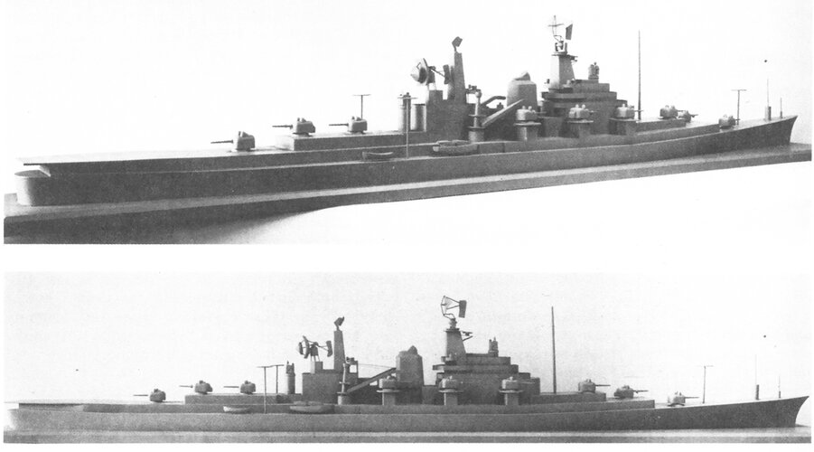
also indeed there was the twin Mark 66 mounting which I've yet to see some official drawings apart from this Mock up model:
also indeed there was the twin Mark 66 mounting which I've yet to see some official drawings apart from this Mock up model:
- Joined
- 16 April 2008
- Messages
- 9,600
- Reaction score
- 14,470
I do wonder why the Navy never developed a 5"/54 automatic twin mounting given the success of the 5"/38 twins during the war. The large destroyers built in the 1950s seem like they would have been ideal for such a system. Perhaps it was recognized that the odds of them engaging in a gun battle with Soviet surface units was pretty slim.
I know about the later Mark 66 but that seems to have been more focused on the fire support mission.
They started on a semi-automatic twin. (Again, from Friedman, US Naval Weapons):
In 1944, the USN was started design work on a new destroyer to be armed with 5"/54 guns. In June 1944, BuOrd began work on a twin 5"/54 mount smaller and more streamlined than the Mk 41 mount for the Montanas. The goal was a shield smaller than the 5"/38 twin, with GUNAR on mount, and an RoF of 18 rpm per tube. The guns were close-set, only 26-inches apart (like the British Mark 6 4.5-inch mount). Crew was to be reduced to 10-12 people on the mount, down from as many as 27 in the twin 5"/38. The deck penetration was to be no larger than the 5"/38 twin, suggesting interest in retrofitting this mount.
But by 1946, new destroyer designs were proposing 5"/54 Mk 42 single mounts instead. This was basically the same mechanism as the twin but with the two halves of the loading system feeding one gun.
Last edited:
Colonial-Marine
UAVs are now friend, drones are the real enemy.
- Joined
- 5 October 2009
- Messages
- 1,468
- Reaction score
- 1,323
I'm surprised this gun mount didn't get its own Mark designation. There does seem to be some conflicting information about it. I've heard it described as both semi-automatic (similar to the 5"/38 and earlier 5"/54 mountings) while others call it automatic. One of the characteristics I've seen listed is:They started on a semi-automatic twin. (Again, from Friedman, US Naval Weapons):
In 1944, the USN was started design work on a new destroyer to be armed with 5"/54 guns. In June 1944, BuOrd began work on a twin 5"/54 mount smaller and more streamlined than the Mk 41 mount for the Montanas. The goal was a shield smaller than the 5"/38 twin, with GUNAR on mount, and an RoF of 18 rpm per tube. The guns were close-set, only 26-inches apart (like the British Mark 6 4.5-inch mount). Crew was to be reduced to 10-12 people on the mount, down from as many as 27 in the twin 5"/38. The deck penetration was to be no larger than the 5"/38 twin, suggesting interest in retrofitting this mount.
But by 1946, new destroyer designs were proposing 5"/54 Mk 42 single mounts instead. This was basically the same mechanism as the twin but with the two halves of the loading system feeding one gun.
"(b) Ammunition for each gun, powder case and projectile, was simultaneously but separately loaded into the hoist and handled automatically thereafter as a unit until fired."
To me this description sort-of matches the way the Mark 42 ammunition drums operate. The rate of fire per barrel is rather low (18 rpm) for an automatic loading system of this caliber, at least compared to post-war projects. But it is quite close to what the Mark 42 can achieve when loading from just one drum.
By 1946 was it generally understood that there would be no more construction of gun cruisers and battleships beyond those already authorized? That would explain a lack of interest in a more ambitious automatic twin gun mount.
- Joined
- 5 May 2007
- Messages
- 1,481
- Reaction score
- 2,855
I wonder if it actually was an earlier stage in the evolution of the Mark 42; as the design developed, someone may well have suggested that one barrel could handle the rate of fire, and allowed some weight savings.I'm surprised this gun mount didn't get its own Mark designation. There does seem to be some conflicting information about it. I've heard it described as both semi-automatic (similar to the 5"/38 and earlier 5"/54 mountings) while others call it automatic. One of the characteristics I've seen listed is:
"(b) Ammunition for each gun, powder case and projectile, was simultaneously but separately loaded into the hoist and handled automatically thereafter as a unit until fired."
To me this description sort-of matches the way the Mark 42 ammunition drums operate. The rate of fire per barrel is rather low (18 rpm) for an automatic loading system of this caliber, at least compared to post-war projects. But it is quite close to what the Mark 42 can achieve when loading from just one drum.
Dilandu
I'm dissatisfied, which means, I exist.
By 1950s, the air defense was considered more important. Single mounts were easier to train fast, than duals, and fast ammo feeding was also easier to implement. Also, nealry everyone assumed in 50s, that artillery would be completely replaced by rockets and missiles soon.I do wonder why the Navy never developed a 5"/54 automatic twin mounting given the success of the 5"/38 twins during the war. The large destroyers built in the 1950s seem like they would have been ideal for such a system. Perhaps it was recognized that the odds of them engaging in a gun battle with Soviet surface units was pretty slim.
Colonial-Marine
UAVs are now friend, drones are the real enemy.
- Joined
- 5 October 2009
- Messages
- 1,468
- Reaction score
- 1,323
Was any more information found on the other proposals (presuming there were ideas for A through E) relating to the 1948 "anti-aircraft battleship" conversion of Kentucky? I am wondering if any might have retained one of the triple 16" turrets. Obviously these have almost no utility for anti-aircraft use but it would still have provided utility in other roles.
- Joined
- 1 February 2011
- Messages
- 2,933
- Reaction score
- 3,611
No documents found. It would be nice to photo the original drawings in normal quality as well. Finding never were US Navy designs seems quite difficult due to the natute how the warships were designed in the USA
Last edited:
- Joined
- 19 July 2016
- Messages
- 4,270
- Reaction score
- 3,452
I cannot help wondering if the trade off is limited flight ops, especially if you intend firing those 16 inch door knockers.
- Joined
- 1 February 2011
- Messages
- 2,933
- Reaction score
- 3,611
The Mark 41 launcher comes in 8-cell (2x4) blocks; that's a fundamental part of the system architecture and can't be changed without significant expenditure. As far as I know, it's always been installed with the long axis of each block perpendicular to the centreline; there may well be a reason for that. Obviously that restricts your layout options.The Tomahawk VLS cells intended for the Phase II Scheme 1 - VSTOL (Battlecarrier / Aviation Battleship) conversion was stated 96 cells.
In my current drawing I've distributed these in 1x60 and 4x9 cells.
Now I'm thinking improving that drawing (As I recently finished all 4 Iowa Phase I drawings) and now I have these arrangement for the VLS:
1x60, 1x20, 4x4.
The 4x4 are at the old 5" barbettes or currently where my 3x3 cells are while the 20 cell pack I though between the Sea Sparrow "Bugeye" Directors in a 4-6-6-4 line (or 2-4x4-2 depending on view).
Alternatively I can lengthen the Flight Deck cell pack to 72 cells in a 6x12 arrangement which would reduce the equipment space of the hanger area somewhat. and reduce the 20 cell pack to just 8 cells.
I'm not sure but maybe the USN preferred 2x2 or 4 cell blocks?
Just remembered!
If you say the Mark 41 VLS launcher comes in 8 cell blocks...
How come the Ticonderogas have 2x61 cell blocks??? The total number of 122 cells could not be divided by 4 or 8!
But checking a photo of the Alreigh Burke they seem to left out 3 cells intentionally???
that_person
ACCESS: Secret
- Joined
- 25 May 2021
- Messages
- 336
- Reaction score
- 641
The original Mk41 systems traded 3 cells for a foldable crane that could reload the cells at sea. But, it couldn’t support the weight of the missiles, and moving around explosives is kind of dangerous, so installation of the crane stopped in the mid-90s.The Mark 41 launcher comes in 8-cell (2x4) blocks; that's a fundamental part of the system architecture and can't be changed without significant expenditure. As far as I know, it's always been installed with the long axis of each block perpendicular to the centreline; there may well be a reason for that. Obviously that restricts your layout options.The Tomahawk VLS cells intended for the Phase II Scheme 1 - VSTOL (Battlecarrier / Aviation Battleship) conversion was stated 96 cells.
In my current drawing I've distributed these in 1x60 and 4x9 cells.
Now I'm thinking improving that drawing (As I recently finished all 4 Iowa Phase I drawings) and now I have these arrangement for the VLS:
1x60, 1x20, 4x4.
The 4x4 are at the old 5" barbettes or currently where my 3x3 cells are while the 20 cell pack I though between the Sea Sparrow "Bugeye" Directors in a 4-6-6-4 line (or 2-4x4-2 depending on view).
Alternatively I can lengthen the Flight Deck cell pack to 72 cells in a 6x12 arrangement which would reduce the equipment space of the hanger area somewhat. and reduce the 20 cell pack to just 8 cells.
I'm not sure but maybe the USN preferred 2x2 or 4 cell blocks?
Just remembered!
If you say the Mark 41 VLS launcher comes in 8 cell blocks...
How come the Ticonderogas have 2x61 cell blocks??? The total number of 122 cells could not be divided by 4 or 8!
But checking a photo of the Alreigh Burke they seem to left out 3 cells intentionally???
Attachments
- Joined
- 16 April 2008
- Messages
- 9,600
- Reaction score
- 14,470
The Mark 41 launcher comes in 8-cell (2x4) blocks; that's a fundamental part of the system architecture and can't be changed without significant expenditure. As far as I know, it's always been installed with the long axis of each block perpendicular to the centreline; there may well be a reason for that. Obviously that restricts your layout options.
FWIW, I can find at least two Mk 41 installations with the modules turned lengthwise: the Fridtjof Nansen class and the ANZAC class frigates (and likely other MEKO 200 ships with Mk 41 VLS). Pics of both at the link below.
Mk.41 Vertical Launching System VLS Navy DDG CG FFG
mk.41 vertical launching system vls navy destroyer cruiser frigate missile
www.seaforces.org
Last edited:
YourChair
ACCESS: Confidential
- Joined
- 24 October 2021
- Messages
- 83
- Reaction score
- 138
I have these CV conversion images from Spring Styles book 4: (pulled off of here: https://www.history.navy.mil/our-co...erical-list-of-images/nhhc-series/s-file.html)
Iowa

Alaska

Unfortunately, no aircraft capacities.
Iowa
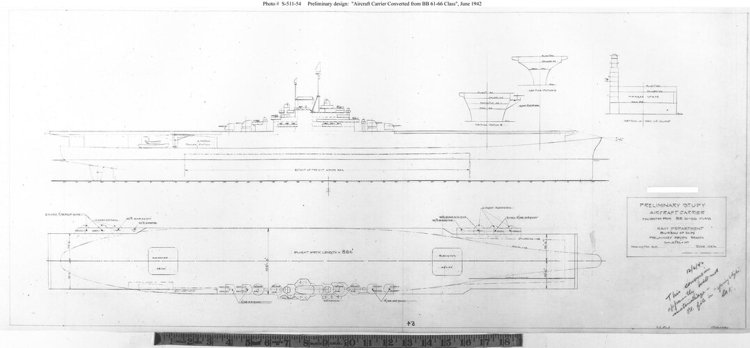
Alaska
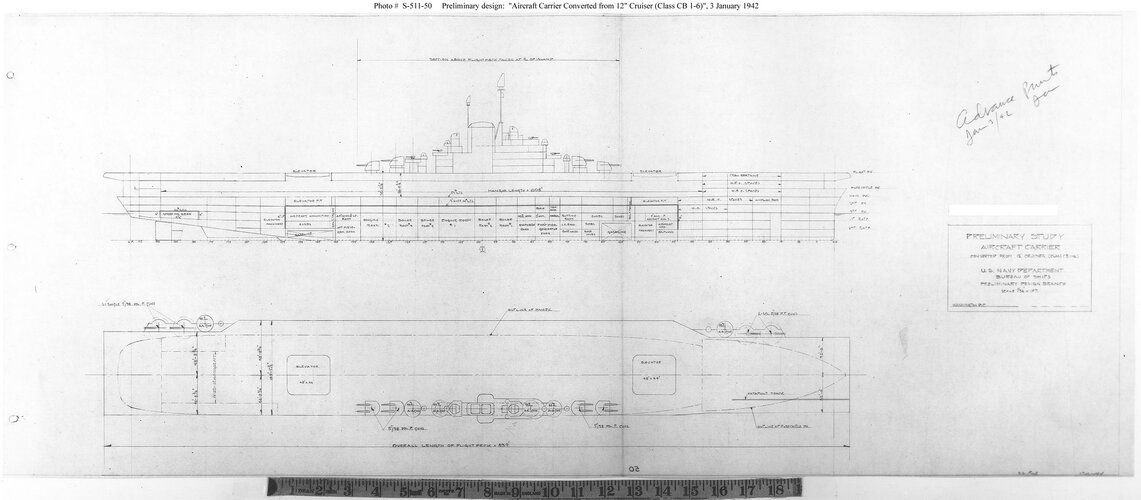
Unfortunately, no aircraft capacities.
that_person
ACCESS: Secret
- Joined
- 25 May 2021
- Messages
- 336
- Reaction score
- 641
Book 3, not 4. The drawings are dated 1942, so not within the 1946-1954 timeframe for Book 4I have these CV conversion images from Spring Styles book 4: (pulled off of here: https://www.history.navy.mil/our-co...erical-list-of-images/nhhc-series/s-file.html)
Iowa
View attachment 678474
Alaska
View attachment 678476
Unfortunately, no aircraft capacities.
YourChair
ACCESS: Confidential
- Joined
- 24 October 2021
- Messages
- 83
- Reaction score
- 138
doesn't hurt to post it againI think I've posted the Iowa carrier conversion study earlier
- Joined
- 1 February 2011
- Messages
- 2,933
- Reaction score
- 3,611
On a tangent, what information is out there for the armored supply/support/replenishment ships?
I've entertained a model converting a SoDak, taking out the after turret and putting in oil and supply booms port and starboard, and a helo deck aft, but that's just a fun idea with no relation to reality.
I've entertained a model converting a SoDak, taking out the after turret and putting in oil and supply booms port and starboard, and a helo deck aft, but that's just a fun idea with no relation to reality.
that_person
ACCESS: Secret
- Joined
- 25 May 2021
- Messages
- 336
- Reaction score
- 641
There’s the drawing from that guy’s book, but he has a history of completely making things up. The actual studies are out there somewhere, but I don’t have the faintest idea whereOn a tangent, what information is out there for the armored supply/support/replenishment ships?
I've entertained a model converting a SoDak, taking out the after turret and putting in oil and supply booms port and starboard, and a helo deck aft, but that's just a fun idea with no relation to reality.
It is odd they seem not to have considered the magazines of the battleships for ammunition storage. There would have been considerable space in the 16" and 5" magazines for a large quantity of shells, and would have been carrying for the most part shells smaller than 16". Using those spaces would have freed the upper decks for other cargo.
Also, such a ship would have a much reduced crew, not having to service the guns, freeing those spaces as well.
Also, such a ship would have a much reduced crew, not having to service the guns, freeing those spaces as well.
SSgtC
ACCESS: Top Secret
- Joined
- 13 July 2020
- Messages
- 1,241
- Reaction score
- 2,888
The magazines weren't designed for the storage of shells. The shells for the guns were stored in the barbetes. The magazines were used to hold the powder bags that the guns used. They were set up very differently.It is odd they seem not to have considered the magazines of the battleships for ammunition storage. There would have been considerable space in the 16" and 5" magazines for a large quantity of shells, and would have been carrying for the most part shells smaller than 16". Using those spaces would have freed the upper decks for other cargo.
Also, such a ship would have a much reduced crew, not having to service the guns, freeing those spaces as well.
- Joined
- 9 October 2009
- Messages
- 21,944
- Reaction score
- 13,570
No it wasn't! The Mk.12 5"/38 fired a 126.6x679mm projectile, whereas the Mk.16 5"/54 fired a 126.6x836mm projectile, which is also the same size used by the Mk.36 (i.e. Mk.45 Mod.4) 5"/54 naval gun...- Replace the gun barrels of the existing (4) 5inch DP-AA Gun turrets to the longer 54 calibre ones. The change would result in a slightly enlarged turret to hold the larger recoil of the guns.
I'm pretty sure this is not possible. You could possibly come up with a way to fit a longer barrel but there would be no point because you'd still have to fire the old 5"/38 ammo out of it. The new 5"/54 ammo is substantially larger and would not fit the old gun at all.
5"/54 projectiles are nearly 6 inches longer and 14 pounds heavier than those for 5"/38. The propellant cases are likewise both longer and heavier. No parts of the gun, hoist, loading tray, or rammer are going to be ok with that unless you do a lot of retrofitting.
Consider, the actual Mk 16 5"/54 semi-automatic gun was essentially a scaled-up version of the 5"/38, and the single Mk 39 turret for that weighed around 33 tons. The comparable 5"/38 Mk 30 weighed a bit less than 19 tons. No amount of retrofitting of the Mk 30 was going to make it work with the new ammo. There's a reason this was never proposed for the literally thousands of old 5"/38 mounts in the world.
If 5"/54 was desired, the only viable path (which was proposed) was to retrofit Mk 45 mounts. They weigh just over 22 tons (excluding hoists) and could actually be made to fit as a nearly direct replacement. But then again, why bother given that there were hundreds of thousands of 5"/38 rounds left in inventory?
Recently found a ship model of the CBC-1 conversion and thought I'd add it here.Those are BCG / Missiel test ship conversion projects not the BCC Battle Command Cruiser plans.
Attachments
BlackBat242
OK, I changed my personal text ;)
- Joined
- 10 April 2013
- Messages
- 1,472
- Reaction score
- 4,256
The GMLS Mk 4 launchers of Boston & Canberra was NOT a "drum", but a racetrack-style magazine, with one rack per arm.Weeeeeeeel...Now that would be one bizarre alternate history "Colorado class in Korean and Vietnam war..."
View attachment 672408
My old idea of "standard" battleship recommissioned in late 1950s (for the war against fascist India-based regime) as artillery/missile platforms. Rear turrets of "Idaho" removed, and adapted version of RIM-2 Terrier launchers (vertical drum magazine, like on "Boston"-class) are jury-rigged over hollowed barbettes.
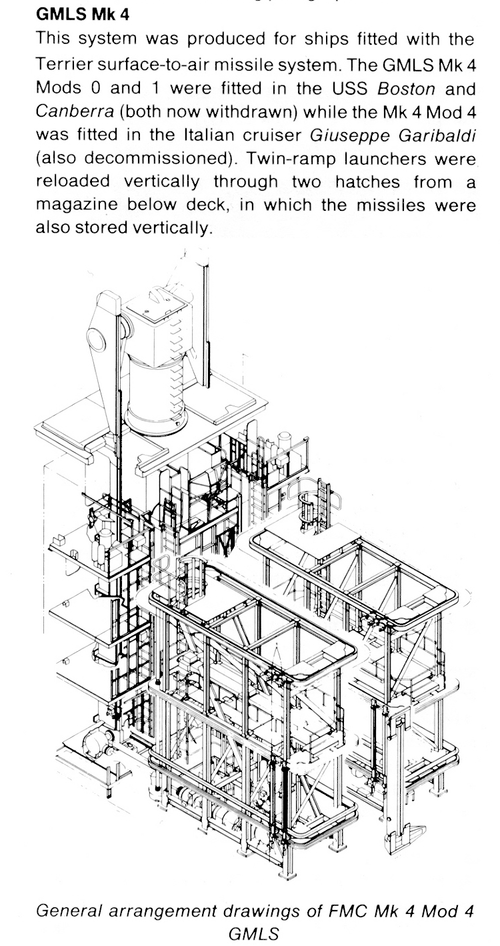
Here is the Mk 26 system - it seems to resemble a modernized Mk 4:
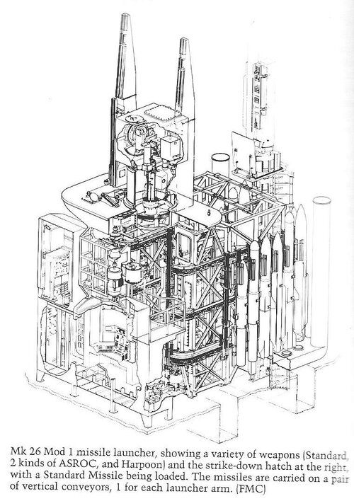
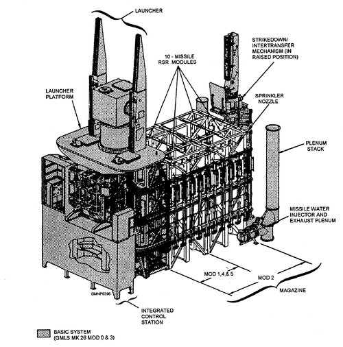
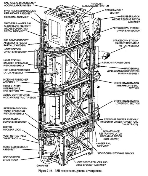
Waaaaait a minute. @Tzoli post 349, upthread.
https://www.secretprojects.co.uk/threads/iowa-and-alaska-class-conversion-projects.7220/post-551242
Made my space nerd heart beat stronger.
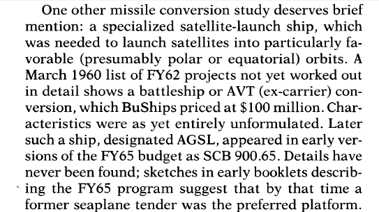
Okay... AGSL. Not "Above Ground or Seal Level" (funny coincidence, isn't it ?) but - the USN official "ship to launch satellites" designation. Quick Google search, will open a separate thread in the space section.
And the seaplane tender considered was AV-4 USS Curtiss - https://www.shipscribe.com/usnaux/AV/AV04.html
Attachments
BlackBat242
OK, I changed my personal text ;)
- Joined
- 10 April 2013
- Messages
- 1,472
- Reaction score
- 4,256
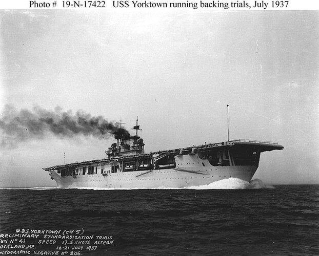
OK - a bit late, but the purely steam turbine driven Yorktown class CVs were designed from the start for reverse air operations, with arresting gear equipment fitted on the bows (7 wires, matching the 7 wires aft).ok so i have never seen this type of conversion. a rear facing catapult you could fit anywhere between 25-35 wildcats/corsairs on that deck if it was crammed it would be interesting to see a carrier/battleship hybrid in action. if these were built earlier and deployed to D-Day action. they would be invalulable providing air support and shore pounding iowa class destruction on gun emplacements. not sure how they would be in ship-ship action in the pacific but they would also be invalulable to the pacific war providing the same power to smaller islandsFrom Global Security:
In 1979 the Navy proposed reactivating the Iowa Class under a two-phase program. Under Phase I the battleships would be brought back into service quickly with a minimum of new modifications. This was done, and all four ships rejoined the fleet. The initial plan also envisioned a Phase II, under which the aft turret was to be deleted and a hanger and flight deck added in its place. The hanger would accommodate 12 AV-8B Harrier STOVL jumpjets. The Martin Marietta version for Phase II had a V-shaped flight deck with two ski jumps on the forward edges, on either side of the main superstructure. The flight decks would measure 330 feet by 150 feet. However, by 1984 the plans for these "Battlecarriers" had been dropped.
Line drawing of Iowa-class aviation conversion circa 1981.
Sources:
http://www.globalsecurity.org/military/systems/ship/bb-61-av.htm
Proceedings July 1981

I don't see the value.
1) stern launching aircraft is a problem, even with a catapult. Ideally, you want more wind over the deck, so you'd need to steam backwards. Ships without turbo electric drive don't do well at this.
2) the cost of such a conversion would surely be higher than just building a CVE, which can (and did) support amphibious landings without compromising the capabilities of a battleship.
Here is a pic of Yorktown running her acceptance trials, making 17.5 knots astern (in reverse):
Here is the flight deck plan (page 6) from the Booklet of General Plans for CV-5 [prepared by the builder, Newport News Shipbuilding, and updated by Navy Yard Norfolk in Jan 1939 and Feb 1940] - click on the image for larger version. Note it points out the arresting wire locations:

- Joined
- 1 February 2011
- Messages
- 2,933
- Reaction score
- 3,611
There is an artwork of one of the Iowas preparred to launch a satellite as well as a carrier I think an Essex:Waaaaait a minute. @Tzoli post 349, upthread.
https://www.secretprojects.co.uk/threads/iowa-and-alaska-class-conversion-projects.7220/post-551242
Made my space nerd heart beat stronger.
Okay... AGSL. Not "Above Ground or Seal Level" (funny coincidence, isn't it ?) but - the USN official "ship to launch satellites" designation. Quick Google search, will open a separate thread in the space section.
And the seaplane tender considered was AV-4 USS Curtiss - https://www.shipscribe.com/usnaux/AV/AV04.html
Ticonderoga subclass eg longhull Essex conversion:
Similar threads
-
-
-
Postwar Royal Navy Battleships? (NOT including the Vanguard!)
- Started by Blacktail
- Replies: 81
-
-

