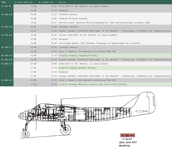
Hi T. A.,

There is a world of difference between the Tego process (called Duramold or Aeromold in the US at the time), and using phenol based adhesives applied by brush or roller. The Tego et. al., process is streets ahead of the phenol glues both in strength and consistency.

Here's a Fairchild video on the Duramold process they were using. It's essentially the same thing as the German Tego process:


Thanks for the link, that's really a great video! It could easily be that Conradis depiction skipped the months of redesign required to get from a Tego design to a conventionally-glued design, and failed to mention the downsides of such a redesign.

David Myhra's "Ta 154" points out that the (7) prototype aircraft were made with the Tego film glue (and after watching the video, I now understand why it's referred to as "film").

Myhra interviewed some Gotthold Matthias (chief aerodynamicists on the Ta 154 project) in the 1980s, and was told that the cause of the crash of a second series Ta 154A (on 28 June 1944), apparently the crash that caused Tank to halt production, was due to sabotage: "''We discovered', said Matthias, 'that the prison labor force was pouring their collective urine into the glue pots ... hence the source of the glue weakening acid.'" I think that's a story with all the ingredients of a good yarn, so I'm more than a bit suspicious about it.

Unfortunately, the book doesn't have an index, and I'm not sure if there's anything else it could tell us about the Tegu film issue.

Regards,

Henning (HoHun)
 
Hi Spicmart,

Though being a state-of-the-art piston engine design aiming for high speed the Ta 154 did not feature a laminar flow wing profile, something most fighter designers were striving for in (very) late-war designs.
Anybody know why it wasn't applied with the Ta 154? Maybe because of the better start and landing characteristics needed for nightfighters when using a more conventional airfoil?

According to Conradis' "Mit Nerven, Herz und Rechenschieber" the reason was that laminar flow was not considered to be practically viable by German engineers as the inevitable inaccuracies of production as well as the normal dust etc. accumulating on the wings in normal operations would suffice to make the flow turbulent anyway. To even have a theoretical chance of laminar flow, production would have to be considerably more accurate and therefore expensive, and with no pay-off expected, a conventional airfoil was chosen.

Conradis was in industry insider, but he wrote in the faux reportage style typical for the 1950s, which involves a lot of fictional dialogue, so I'm not sure how far he can be trusted.

I believe there's a NACA report on the P-51 laminar flow wing which illustrates the performance loss the laminar flow wing experiences under (simulated) real-world conditions.

(Howver, "laminar" airfoils also seem to have advantages in the transonic regime, and I believe these are not as badly affected by surface roughness as the laminar flow is ...)

Regards,

Henning (HoHun)

But as far as I know the laminar wing profile did give the P-51 an advantage of less all-around drag and go faster than contemporaries despite less engine power and higher parasite drag.
Same with other late designs like the Sea Fury or Spiteful.
So despite these restrictions for true laminar flow mentioned, there had to be some benefit in such a wing.
From my understanding of many different sources, drag difference between the Spitfire and P-51 was give and take and the radiator setup in the P-51 was quite beneficial so the overall result was better speed for the P-51. The Spiteful was considered little if any improvement over the Spitfire.
The P-51 radiator installation produced more net thrust than drag. Laminar flow could not be maintained in practice, since even the tiniest surface imperfections--such as bugs killed in flight--were enough to disturb the flow. When it came to speed performance, the Spiteful;s laminar-flow wing proved inferior to the Spitfire wing because it had a higher thickness to chord ratio that exacerbated handling problems at trans-sonic speeds, such as those encountered in dives.
 
Hi Iverson,

The P-51 radiator installation produced more net thrust than drag. Laminar flow could not be maintained in practice, since even the tiniest surface imperfections--such as bugs killed in flight--were enough to disturb the flow. When it came to speed performance, the Spiteful;s laminar-flow wing proved inferior to the Spitfire wing because it had a higher thickness to chord ratio that exacerbated handling problems at trans-sonic speeds, such as those encountered in dives.

Some quotes from David Lednicer and Ian Gilchrist of Analytical Methods Inc. in their 1991 AIAA article "A Retrospective: Computational Aerodynamic Analysis Methods Applied to the P-51 Mustang":

"The Mustang is particularly intriguing because much aerodynamic legend and lore surrounds the aircraft, but few hard facts are ever discussed. Stroies of the extensive laminar flow on the wing and how the cooling system produces thrust are often told. The current work intends to investigate the Mustang's aerodynamics analytically and then to project what can be done to extend the Mustang's capabilities as a racing airplane."

"Another piece of Mustang aerodynamic folklore is that the cooling system produced a net thrust. As noted elsewhere, available literature on this subject is entirtely theoretical and is divided between a favourable British position and adverse American and German positions. The issue was explored using the experience gained with auomotive radiator duct work at AMI. [...] At what might be typical cruise operating conditions, a pressure drop of 13.3 in H2O on the water/glycol radiator and 32.8 in H2O on the oil radiator is found. Coupled with an assumed 170° F outlet air tempature, a drag of 29 lb. is incurred. At this high-speed cruise condition (M = 0.5) at 15,000 feet, the cooling system drag is approximately 2-3 % of total airframe drag. What particularly hinders the cooling ssystem as a thrust-producing device is its low propulsive efficiency. Figure 18 shows that by increasing the outlet air temperature, there is the potential for an increase in the thrust by the system."

(Figure 18 shows that total system drag drops to 0 at an outlet air temperature of 182 °F.)

The analysis by Lednicer and Gilchrist found several points in which the P-51 cooling system was not optimal, and also analyzed the Reno Racer "Strega's" cooling system, stating that the extended exit door on Straga eliminated the vortex along the sides of the cooling system exhaust chute aft of the trailing edge of the door. However, Stregas custom cooling air duct (instead of intercooling, water injection is used, with the previous intercooler position now being used for an oil cooler) was found to be inefficient as it suffered from flow separation well before the radiator face, and a new and improved duct was designed for Strega as a result of this analysis. The new duct includes a bondary-layer diverter.

By the way, Messerschmitt ran a test with the cooling system of the Me 109 (by actually installing two separate cooling systems in one test mule), and found, under somewhat different conditions than those outlined above for the P-51, that the total speed loss due to the cold cooling system was 6%, with the heat of the coolant reducing this to 5% (recovering about 1% of total speed, at 950 HP propeller shaft power).

The results might not be entirely representative for aircraft in standard condition, but the purpose of test was to evaluate a belly cooler against the wing radiators, and these were found to be equally efficient aerodynamically, within the error margins of the test.


Regards,

Henning (HoHun)
 

Wood has a much smoother finish than metal surfaces which require rivetting. Wouldn't this make laminar flow possible?
 
Last edited by a moderator:

Wood has a much smoother finish than metal surfaces which require rivetting. Wouldn't this make laminar flow possible?
My understanding is that the factory finish is not the problem. The problem is the chips, dents, dirt, and squashed bugs that accumulate almost immediately in use. Very small variations from smooth are said to cause major problems for laminar flow airfoils.
 
Last edited by a moderator:
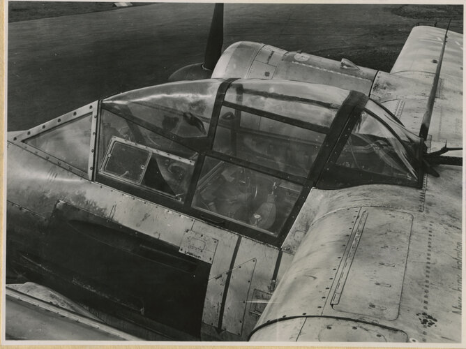
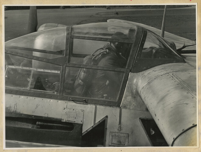
Why hasn't a midwing configuration for the Ta 154 been selected in the first place ( or at least one similar to the He 219)? That would have circumvented the pilot's bad view problem.
 
Last edited:
Why hasn't been a midwing configuration for the Ta 154 been selected in the first place ( or at least one similar to the He 219? That would have circumvented the pilot's bad view problem.
Hi Spicmart,

The 1942 taildragger configuration was a midwing layout.

Midwing nose wheel aircraft have the disadvantage of requiring a longer and thus heavier or more fragile nose wheel strut to get sufficient ground clearance.

Nose wheel configuration was seen by the Luftwaffe as desirable for night operations ... not sure when that sunk in, but I presume that's why they didn't pursue the taildragger configuration.

It might be that structural considerations also had to do something with moving away from the high wing layout, but I am not positive on that.

Regards,

Henning (HoHun)
 
newsdeskdan said:
Justo Miranda said:
Fw 190 V32/U1... Ta 153???

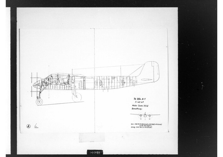
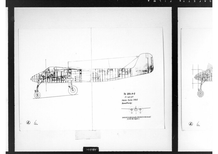
Justo, your drawing is from the Ta 152 H brochure (albeit with the original caption chopped off and a new one with the same wording added), although the Ta 254 A-1, A-2 and A-3 did use the Jumo 213 E.
I was asking Sienar which aircraft he wanted drawings of the annular radiator installation from. The earliest Ta 154 design, just after the redesignation from Ta 211, had the Jumo 211 F. Thereafter, the only other Ta 154 designs which didn't use the Jumo 211 (the Jumo 211 N in production) were the V8, V10, V22 and V23, C-1, C-2 and C-3, and the Ta 254 B-1 and B-3 (with the latter being specified with the DB 603 L).

Photos of the early Vs and production A series show a ring or "achsial" radiator assembly while some FW artwork of the 254 shows what looks like a drum or "trommel" type.

I'm wondering when FW did this change. A similar switch occurred with the 190D to 152, with the D having an ring type and the 152 adopting the drum. Its my understanding that the drum style annular installation was a messerschmitt/DB innovation.

What are the advantages of a drum cooling matrix compared to the annular one? I guess cooling surface increased but so does drag. Messerschmitt always preferred underwing radiators. So with them creating the drum rad together with DB, does that mean that they would adopt the ring/drum cooling configuration common to other German aircraft?
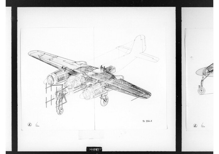
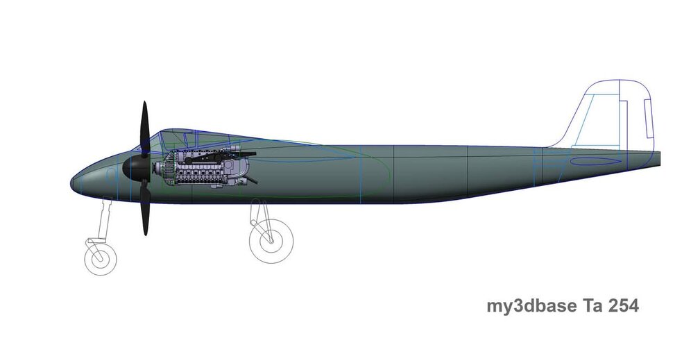
Small front section and neat wing profile.
 
I have several books about the Ta 154. Can the Monogram Close-up 22 from 1983 be recommended?
 
Hi Tomo,

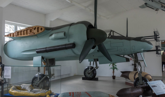
Any takers on what kind of wing profile the Ta 154 had, judging by this picture?

I just came across this picture of a replica Ta 154 in a museum at Rechlin:


Since the outer wings aren't mounted, it shows the wing profile at the mounting point.

Regards,

Henning (HoHun)
 

Attachments

  • 436.jpg
    436.jpg
    954.9 KB · Views: 36
  • 437.jpg
    437.jpg
    1.3 MB · Views: 31
  • 438.jpg
    438.jpg
    1.7 MB · Views: 33
  • 439.jpg
    439.jpg
    901.9 KB · Views: 33
  • 440.jpg
    440.jpg
    327.4 KB · Views: 39
  • 442.jpg
    442.jpg
    1.2 MB · Views: 42
Hi Tomo,

Any takers on what kind of wing profile the Ta 154 had, judging by this picture?

I just came across this picture of a replica Ta 154 in a museum at Rechlin:


Since the outer wings aren't mounted, it shows the wing profile at the mounting point.

Regards,

Henning (HoHun)
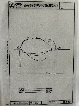
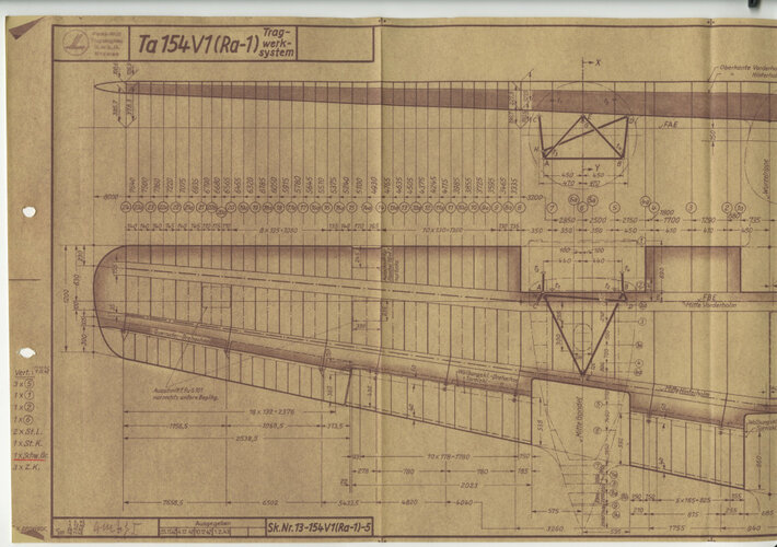
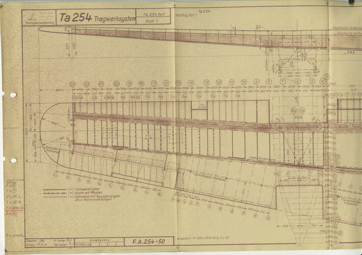
Tomo earlier posted a similar question on another forum where in response I yesterday posted part of an original drawing showing wing profiles of the Ta 154V1.
For those of you interested: https://ww2aircraft.net/forum/threads/wing-profile-of-used-on-the-ta-154.60524/post-1820199

The wing profile of the Rechlin Museum replica may or may not be accurate.
I can't see that particular photo as it requires a log in but I am not a member of flugzeugforum.
However to compare the replica wing profile with the profile on the original drawing would require a replica photo taken under exactly the right angle, which sofar I have never seen.
 
From this photo of the Flickr site it is indeed very difficult to know what kind of profile we are dealing with ...


1678793930771.png
 
Hi Tomo,

Any takers on what kind of wing profile the Ta 154 had, judging by this picture?

I just came across this picture of a replica Ta 154 in a museum at Rechlin:


Since the outer wings aren't mounted, it shows the wing profile at the mounting point.

Regards,

Henning (HoHun)
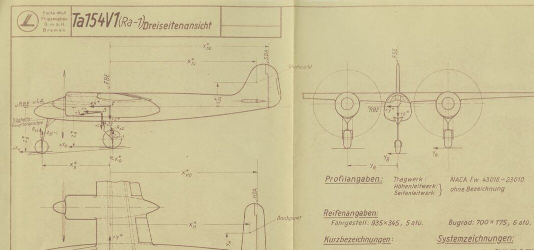
Tomo earlier posted a similar question on another forum where in response I yesterday posted part of an original drawing showing wing profiles of the Ta 154V1.
For those of you interested: https://ww2aircraft.net/forum/threads/wing-profile-of-used-on-the-ta-154.60524/post-1820199

The wing profile of the Rechlin Museum replica may or may not be accurate.
I can't see that particular photo as it requires a log in but I am not a member of flugzeugforum.
However to compare the replica wing profile with the profile on the original drawing would require a replica photo taken under exactly the right angle, which sofar I have never seen.
Using the last image on the page. This is a NACA 3316. A 2216 might match better.
fdsafasdf.png
 
Based on my pixel counts:

The 'Schnitt E-F' wing profile has a maximum camber of about 20 % of chord, located in the region of 10 to 20 % of chord. Maximum airfoil thickness is about 17 % of chord (at about 31 % of chord).
Based on this my best guess is that this resembles a NACA 2217 if this is a 4-digit airfoil.

The 'Schnitt J-K' wing profile has a maximum camber of about 18 % of chord, located at about 40 % of chord.
Maximum airfoil thickness is about 15 % of chord (at about 31 % of chord).
Based on this my best guess is that this resembles a NACA 2415 if this is a 4-digit airfoil.

However it could also be that Tank used a 5-digit NACA airfoil, like he used for the Fw 190 which, according to David Lednicer (World War II Fighter Aerodynamics), had a root airfoil NACA 23015 and a tip airfoil NACA 23009.
 
Hi Dan,


Awesome, thanks a lot! :) Interesting to see that the section is designated as "NACA Fw" - seems Focke-Wulf was into modifying NACA airfoils, too. I believe the German notation system for modifying NACA airfoils actually became sort of official after the war, but in the above airfoil designations, this system isn't directly evident.

Regards,

Henning (HoHun)
 
Last edited:
Hi Spicmart,

I wonder what aerodynamic purpose this "dent" at the frontal underside of the profile serve?

I believe the conventional name for that dent is "cusp". As the NACA didn't design airfoils for any specific purpose, but instead specified mathematical functions to define airfoils that were then tested in the wind tunnel, it didn't really serve any purpose but was a byproduct of the math they used. Of course, it might contribute to the suitability of the airfoil in question for any particular application, but I'm not that deep into airfoils ...

There seems to be a "standard" modifiation that eliminates the cusp, but that might have been created more in the interest of ease of manufacture than for its aerodynamic properties, but again, I don't really know. I've seen it referred to as "A" modification, but I'm not quite sure where the "A" would go into the airfoil designation ...

Regards,

Henning (HoHun)
 

Similar threads

Please donate to support the forum.

Back
Top Bottom