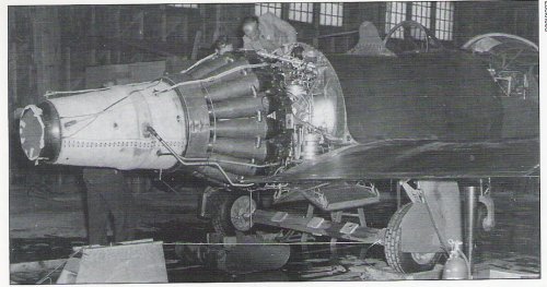
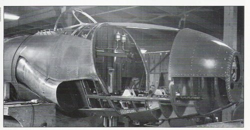
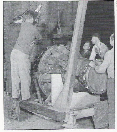
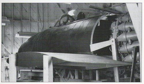
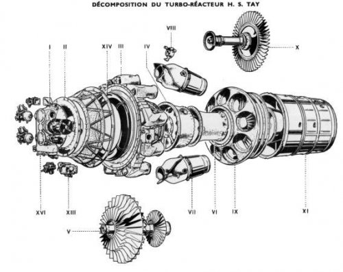
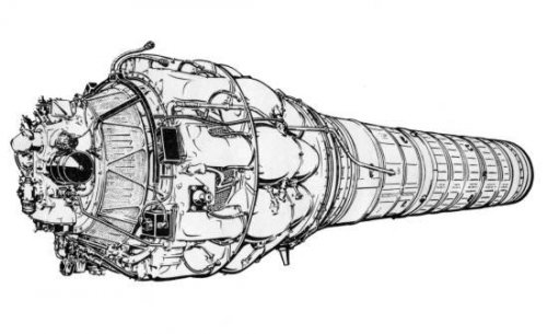
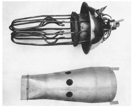
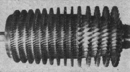
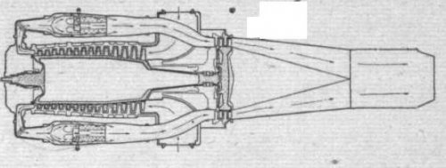
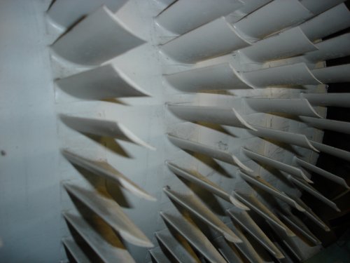
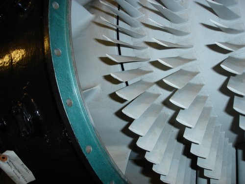
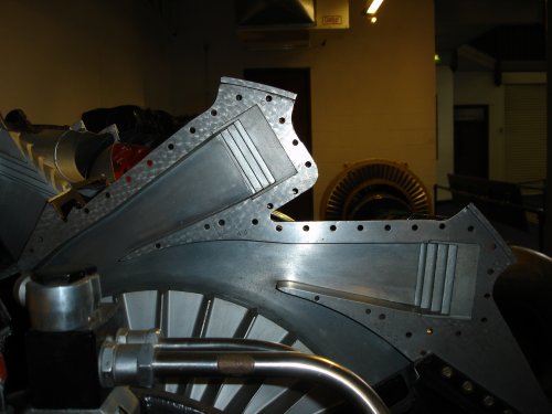
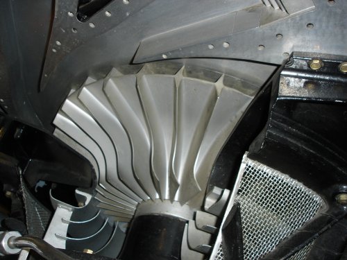
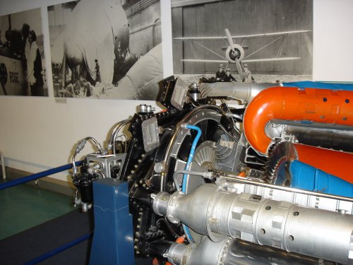
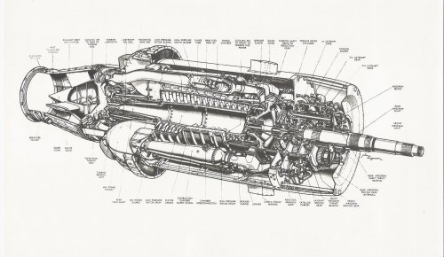
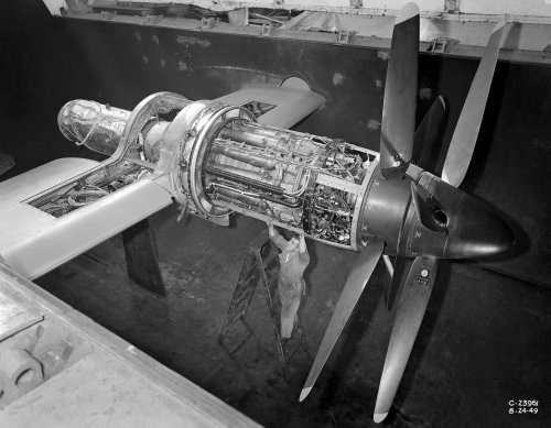
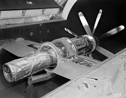
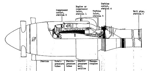
The Rolls-Royce Nene and Tay linked to Pratt and Whitney:

Pratt and Whitney were late getting into gas turbines as the US military did not want them distracted from piston engine manufacture during WW2.
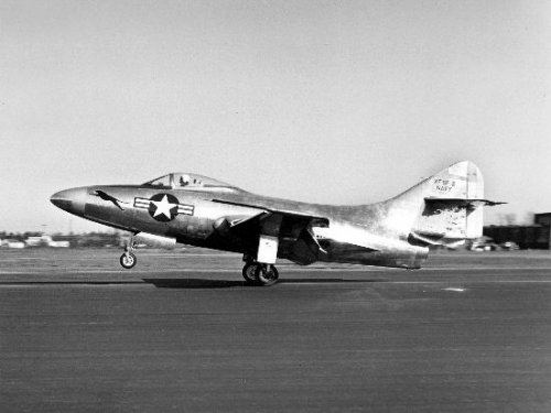
In the meantime Rolls-Royce were looking for new post-war markets in order to maintain revenue streams. In January 1946 a Philip Taylor contacted Hives with a request for a licence to manufacture and sell RR turbine engines in the USA. As the potential for sales in the USA was very attractive negotiations ensued and Taylor, who was the ex-chief engineer at Curtiss-Wright. Hives was reluctant to talk to him at first ...but after some negotiation Taylor signed a contract granting him sales rights to the Nene and Derwent and their spares for two years with a one-year getout clause. Taylor began negotiations with Grumman to supply Nenes and also with Pratt and Whitney. In Jan 1947 Taylor contacted RR with the news that P&W wanted to manufacture Nenes for Grummans under a sub-licence deal. C. J McCarthy vice president of United Aircraft Corporation, owners of P&W, had been given open house by Hives when he visited the UK in the summer of 1946 and so Hives contacted him to say Taylor had been in touch re-P&W licencing. In March 1947 Hives thought the deal so important that he sailed on the 'Queen Elizabeth to the USA to finalise a deal with P&W who were being encouraged by the US Navy to licence the Nene engine as it was more powerful and reliable than US engines and with the cold war starting they needed all the engines that they could get. Taylor eventually drops out of the picture after threatening to sue but P&W reached an accommodation. In May 1947 the Navy announced the deal between P&W and RR for the F9F carrier fighter from Grumman.

Hobbs, boss of P&W, was concerned that Hives was too keen on the axial AJ65 to keep developing the Nene series, but in fact the Tay engine was proposed as the next engine for P&W.
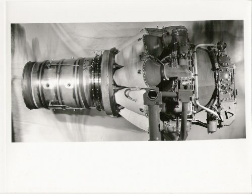
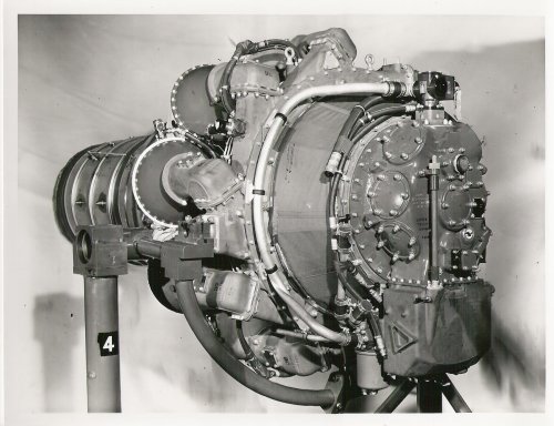
P&W had a team of engineers at Derby to work on the American version of the Nene and then to help design the Tay, essentially an uprated Nene for later versions of the Panther, as the Grumman F9F had been christened. The F9F-2 Nene powered version first flew on 27th November 1947, Gwinn(of P&W) cabled Derby: "Grumman Nene was flown yesterday for one hour, 15 minutes.Everything O.K. Pilot very pleased and snap rolled machine."
Jim Boales was one of the RR Derby engineers who had responsibility for making the relationship work and he spent time in East Hartford as well as working in Derby on both the Nene and Tay. The Tay he told me came about because the Navy kept hanging more things onto the aeroplane and so extra power was needed, initially by water-methanol injection on the Nene raising the power from 5,000 to 5,750 then 5,950 lbt, but eventually by enlarging the Nene itself. The challenge was to accommodate a 1.14 times linear scale of the Nene within the airframe of the Panther. The Overall diameter of the Nene is 49.5 in, so the scale-up would give a diameter of 56.43 in.- too big to fit in the hole! The largest diameter that could be accommodated was 50 in so the RR/P&W design and engineering team at Derby started to determine what needed to be done to bring the engine into line with that figure!

......continued in#124 below.
 

Attachments

  • RR-WP3643-!st Pratt and Whitney Nene.jpg
    RR-WP3643-!st Pratt and Whitney Nene.jpg
    240.2 KB · Views: 531
  • RR-WP3639-!st Pratt and Whitney Nene- front 3qurtr.jpg
    RR-WP3639-!st Pratt and Whitney Nene- front 3qurtr.jpg
    331 KB · Views: 509
  • 4561354329_239fb6e05d_o.jpg
    4561354329_239fb6e05d_o.jpg
    30.8 KB · Views: 494
The US back-story here (in part) is that the USN had bet most of the rent on Westinghouse, which believed in small engines used in large numbers, and thought that jet engines could be scaled easily, despite having no aviation experience. The outcome was two engines that were too small to be of much practical use except as boosters (J30 and J32), the unexciting J34 (two engines required for decidedly subsonic fighters) and the catastrophic J40.

Did centrifugals offer better throttle response at the time?
 
My gut response is that in the 1940s a centrifugal is less sensitive to abuse than an axial both in terms of control and mechanical integrity... most axials of that time seem to have a long development period whilst surge was tamed or vibration related blade failures were tuned out. The flatter performance characteristics of the CF vs. axial compressor helps but does not eliminate surge problems.
The US government originally put all its eggs in the axial basket which is why Whittle's machine was grabbed so quickly when offered by Britain. P&W after the war had ended also realised that Allison/GE were not getting on with development of the centrifugal with enough urgency and so, as RR were activally looking for outlets in the US, they took a licence for the Nene and later the Tay, as we are exploring at present. Westinghouse did well to design two small but good turbojets. They scaled up in ambition with the J34 which at least did what it was designed to do. The J40 was a disaster that ruined many aircraft programmes. Westinghouse had entered into a licence agreement with Rolls-Royce and managed to screw up the transfer of technolgy to the USA on both the Soar and the late-model Avons. Geoff Wilde got involved in sorting the J-40 engine problems, but it was cancelled before all the changes could be demonstrated to work... Geoff regarded the Westinghouse venture a total waste of RR engineering time but Pearson was able to point out that the royalty payments were very large and very welcome when lean times were upon the UK market. David Huddie was told in September 1959 that Westinghouse were out of the aero engine business.
 
As I intimated above, Jim Boales made a major contribution to the successful development of the RB44 Tay and later the Hispano Suiza Verdon engines. Below is a retelling of those times from notes I made after conversations with him in the mid-60s!
Encouraged by the growth in demand for more powerful engines for use by yhre military P&W turned to RR for advice on how to uprate the Nene. The Tay was the resulting engine, designed in Derby by a joint team that decided to scale the Nene by 14% linear.
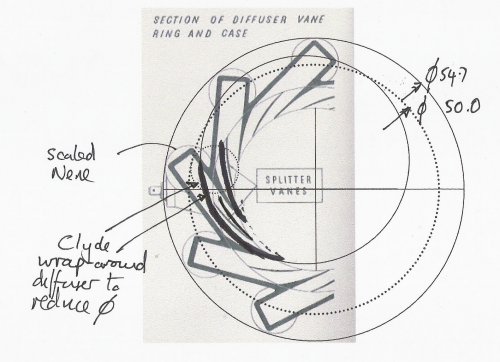
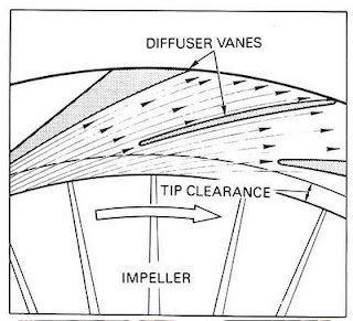
The Overall diameter was limited to 50 inches by installation considerations. The larger impeller was 2 inches greater in diameter than the existing Nene making it 32.8 in. Tests with a larger impeller on the Nene had shown that the tip clearance could safely be reduced from the 1.025 in. to 0.67 in. which was also the figure for the Clyde. The Clyde also employed wrap around diffuser passages to the combustion chambers. This has the effect of reducing the flow area for the rear entry of the impeller but has been found not to penalise overall performance. Adopting this enabled the diameter to shrink to the required 50 in. To improve airflow through the impeller it was decided to allocate the 14% extra axial width by changing the relative proportions of the rotating guide vanes and the impeller itself, reducing the latter dimension. This allows smoother entry for the air and achieves greater efficiency
In order to control the weight many large components cast in aluminium were cast in Magnesium which turned out to be very satisfactory. an experiment was tried out: casting the impeller in Magnesium but was a step too far.
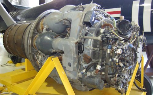
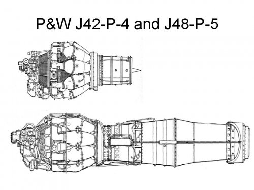
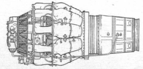
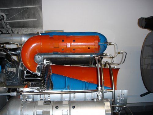
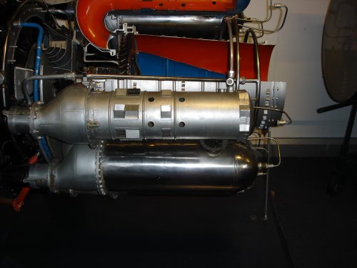
The third picture shows a J42 and J48 side view roughly to the same scale! The afterburner was initiated early in the Tay programme...
The photo of the J48 should be compared with the Tay photo posted earlier.
Rolls-Royce and P&W agreed a delivery programme for prototype engines in June 1948 that would result in 4 engines being constructed:
1st engine for RR by Oct '48
1st engine to be despatched to P&W Nov '48
2nd engine for RR Dec '48
2nd engine P&W end Jan '49
3rd engine P&W end Feb '49
3rd engine for RR end March '49
4th engine P&W end April '49.

In the end RR built 34 Tay engines to support all the development activity:
8 prototype flight engines for P&W
6 RR development for Ministry of Supply (2 for Lancastrian)
4 for the Viscount
6 for English Electric
6 for the Avro Tudor
all 34 were delivered by end of 1949.

To assist with RRs workload P&W assumed design responsibility for the design of Tay jetpipe and afterburner for the North American P86, but will submit their designs to RR for comment. Initial design of jet pipe was based on reheat sizes but without reheat system or variable nozzle.
P&W will place an order, when RR is ready, for 2-3 afterburners but in the meantime they carried the workload themselves, using drawings of the RR design of clamshell nozzle.
The programme was very successful and a large number of J48s was produced by P&W. Production numbers at P&W were:
Nene: 1,137 and
Tay: 4,021.
Typical specs were:
J42-P-6 J48-P-5
Dia (in.) 49.5 50
Len (in.) 103.2 236
Dry weight (lb.) 1729 2000
PR 4.3 4
Max thrust (lb) @ 5750 (wi) 8,500 to 9,000 (7,000 with wi)
rpm 12300 11,000
wi= water injection
 

Attachments

  • prattj48p6a_large.jpg
    prattj48p6a_large.jpg
    67.2 KB · Views: 117
  • J42 and 48 comparison side views.jpg
    J42 and 48 comparison side views.jpg
    73.9 KB · Views: 126
  • RR Tay-reduced diam by using clyde wraparound diffuser.jpg
    RR Tay-reduced diam by using clyde wraparound diffuser.jpg
    223.2 KB · Views: 142
  • 8.jpg
    8.jpg
    27.8 KB · Views: 459
Immediately after the war there was a surge of interest in automotive applications for the gas turbine. Rover developed a 100 hp engine suitable for their production car, Centrax looked at the lorry market with a 160 hp designed by ex-employees of Power Jets, and Rolls-Royce looked at the feasibility of a small engine for automotive or small aircraft application.
Jim Boales was involved in this investigation and extracts from an undated report (late 46 or early 47) reads:
" there are many uses foreseen for a 500 bhp engine, e.g. cars, light aircraft, where about 200 hp is needed or a trainer aircraft.
Advantages: lightness, simplicity, no gear changing or clutches. For traction purposes a free turbine is desirable, then engine power is not directly related to power turbine torque is obtained for starting. Also [the free turbine arrangement has] general uses for investigating different turbine arrangements, control systems, heat exchangers, etc.
For such an engine it was considered desirable to use an existing compressor that does not need development and a reasonably high pressure ratio, about 5:1. The free turbine enables the engine to be run as a pure jet. This greatly helps as the free turbine can be developed separately.
As a turbine power generator it is desirable to keep the leaving velocity from the turbine down to the minimum possible. Thus a low axial velocity turbine will have to be incorporated."

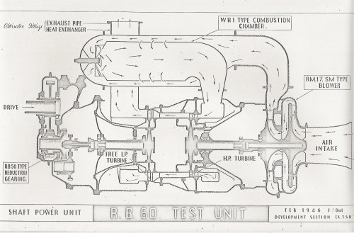
The RB60 engine was configured as:
"A Merlin 46 2-stage blower delivering via its own volute and single delivery pipe into a single reverse flow combustion chamber, from which the hot gas flows into an annular volute at entry to the high pressure turbine. This is a single stage turbine. The gas then flows through an annulus about 6 inches long to the low pressure turbine. This drives a gearbox at the rear.
The engine is fitted with an oil tank and pumps fitted to the h-p section wheelcase, and on the l-p section for the reduction gear and power turbine.
The cooling air for both turbine casings is an external supply. The wheelcase driven by the h-p unit carries the starter motor, fuel pump, oil pumps and tachometer. The fuel control systems apart from pump is mounted separately."

Jim Boales said that the turbojet ran at Barnoldswick but the power turbine was never built as there were other priorities.
The design performance was:
Press ratio 5:1
compressory efficiency 72.5%
Power output/lb/sec 64 bhp at a gearbox efficiency of 98%
so for 7lb/sec flow the output was 450 bhp at an sfc 0.845
Hp rpm 22,800
lp rpm 17,200
performance as a jet:
jet velocity 1025 ft/sec
total thrust 350 lb
sfc 1.08
 

Attachments

  • RR-RB60-Dnl dwg-feb 46.jpg
    RR-RB60-Dnl dwg-feb 46.jpg
    514.3 KB · Views: 138
tartle said:
Immediately after the war there was a surge of interest in automotive applications for the gas turbine. Rover developed a 100 hp engine suitable for their production car, Centrax looked at the lorry market with a 160 hp designed by ex-employees of Power Jets, and Rolls-Royce looked at the feasibility of a small engine for automotive or small aircraft application.

Is this the work that led to the Leyland Turbine truck of 1968?


Leyland Turbine by aecsouthall, on Flickr


Leyland Gas Turbine by gylesnikki, on Flickr
 
Not to mention similar work that was done on cars by Rover: http://www.rover.org.nz/pages/jet/jet5.htm

And trains by Metropolitan Vickers (BR18100) and English Electric with the GT3: http://www.enuii.org/vulcan_foundry/oddities/gt3.htm
 
Hobbes... the Leyland organisation acquired Rover in 1967 and its gas turbine research work which had continued all through the 50s and 60s was directed at powering a Leyland truck. There is a pic below from a brochure which can be read here
JFC Fuller ..and boats as we have already discussed.
 

Attachments

  • Leyland truck engine.jpg
    Leyland truck engine.jpg
    102.9 KB · Views: 118
I am intrigued by a review of the thesis The Development and Production of Turbojet Aero-engines in Britain, Germany and the United States by Hermione Giffard. Imperial College London, 2011. ... which leads me to think about how Rolls-Royce and Metrovick did not have the (gas turbine aero engine) field to themselves.

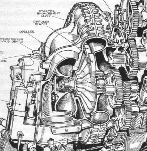
George Bulman who was DEngRD for aero engines up until his retirement in 1943 relates how Tizard, head of R&D at the MAP (until Lindeman got him removed in 1942... an old feud.. was there a war on?) became increasingly concerned with Whittle's erratic responses to concerns about the speed of development.. decided to involve Frank Halford and de Havilland in the jet engine programme. Frank Halford, aided by Moult and Brodie had produced ranges of piston engines for de Havilland and Napier, of varying degrees of success (often constrained by those two organisations) and was asked to think of the sort of jet engine they could design for dH. Given their expertise in superchargers, such as the elegant Gipsy Twelve engine (see Flight article from which the supercharger drawing comes) and the Napier Sabre, it is not surprising this is where Halford started. With some, but limited access, to all the work then being sponsored the team went for an engine of 2,000 lbt and sized a supercharger impeller to suit. This was necessarily of larger diameter than Whittle's twin-sided design and alarmed the RAE who were aware of the failiures on Whittle's jets. However Halford's close relationship with Wallace Devereux at High Duty Alloys meant they were confident they could deliver a reliable impeller. Isaac Lubbock of Shell had been brought in to help Power Jets combustion challenges and this work was of great influence... Halford realised that two 180 degree bends in the Whittle reverse flow scheme increased the risk of uncertain combustion conditions as well as being a source of pressure loss so they opted for a straight through layout from day 1. They were not concerned about the shaft whirling issues as the single sided impeller design meant that no axial space was needed for the rear intake and so it was the diffuser elbow and combustion chamber length alone that determined the dimension from impeller to turbine, which could be linked by a simple shaft of appropriate (large) diameter. Also the straight through layout enabled the adoption of a larger diameter turbine (not constrained by the reverse-flow combustion chambers). Progress on turbine disc materials also helped in this respect... so all this thinking without constraints imposed on Whittle a few years before resulted in the H.1, later known as the Goblin engine. A basic section highlighting the features is included below.
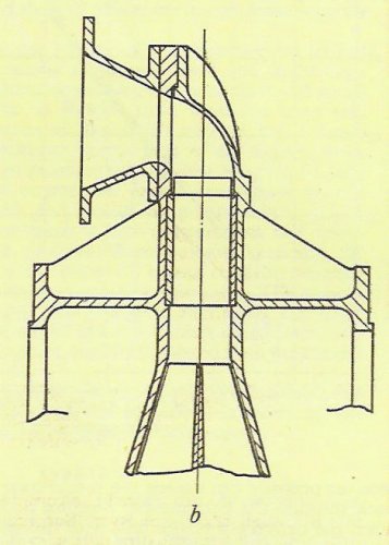
As the various claims made by engine designers are not always as clear cut in practice as they are in theory I thought I would make an unfair comparison by putting a section of the 49.5 inch diameter Nene alongside the 49.85 inch diameter Goblin... see below... it is a really unfair comparison as the thrusts and therefore mass flows are not the same but we can see the Nene is a bit longer in shaft dimension than the Goblin... but the Goblin shaft diameter is relatively large... i. e. much stiffer. But the complexity that goes with a three bearing system on the Nene is certainly more complex than that needed on the Goblin two bearing system.

The MAP and the Air Ministry noted the lack of paranoia as the aero firm just got on with the job... just a touch more challenging than a Gipsy Twelve but may be not as bad as a Napier Sabre?
de Havilland had their challenges but this was to develop the rated power and sufficient longevity to make it a Serviceable engine for the military. The engine design started in April 1941 and as there was a closeness with the aircraft side of the business, the Spider Crab aeroplane design carried on in parallel... resulting in the engine featuring a bifurcated intake so that the ducting from the wing root air inlets was minimised. The first drawings were issued to the experimental shop on 8th August 1941 and a mere 248 days later the H1 made its first test run on 13th April 1942. Two days later the team were confident enough to carry out a half hour acceptance test at half design speed. On the 5th May the engine suddenly stopped- on investigation it was found that the intake had been sucked flat starving the engine of air and stalling the compressor. after stripping the engine little damage was found and soon it was rebuilt. Initial troubles involved difficulties in starting the engine, overcome by fitting two starter motors, and combustion issues leading to continuous improvements as the hours built up, as well as improving welding quality for longevity. The tailpipe was also liable to buckle so it was reinforced. Fuel supply difficulties were also experienced as the pump capacity was inadequate, so was increased. There were one or two impeller failures but the issues were diagnosed and fixed.. to be discussed later.
After the strip and rebuild after the incident of May 5th the engine was taken up to full speed on 2nd June reaching the design thrust of 3,000 lb. By the end of July the board of de Havilland were investigating how they were to put the engine into production. On 10th September they received an official Ministry request for a detailed manufacturing plan which was submitted on 18th. On 26th September the engine completed a 25 hour flight approval test; a total of around 120 hours had been achieved in the overall test programme. Two years after the engine programme began the Goblin was ready to fly. However its designated Spider Crab or Vampire as it was to become, was not. The Mosquito and Hornet had been the focus of DH's attention and so the programme slipped. Meanwhile the other British jet fighter was suffering just the opposite problem... the E1/44 (Meteor) was virtually ready but the Power Jets engine was not. It seemed a good idea to look at the feasibility of 'Goblining' the Meteor.
George Carter realised that if the Goblin intake was spun through 90 degrees the air inlet to the engine could be above and below the wing spar making the installation fairly straight forward. The Goblins were installed and cleared for flight at 2,300 lbt, 300 lb more than previously cleared by the simple expedient of increasing max rpm to 9,300 an increase of 300 rpm.So the Meteor and Goblin made their maiden flight on 20th Sept 1943.
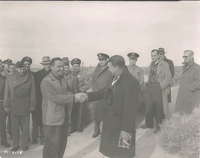
The British and Americans had been discussing the Goblin and the US Military decided to go ahead with Lockheed on an aircraft with one of these engines. The Lockheed XP-80 was the first product of Kelly Johnson's Skunkworks. June 23rd 1943 was the official start date and it was intended to fly 150 days later. he contract called for the aircraft to be completed in 180 days so the pressure was on! A crude mockup of the Goblin arrived on July 10th and it was the lack of engine which was the critical item for delivering the contractual timespan. August 24th saw the British Air Commission informing the Americans that a non-flyable engine was about to ship. A month later the engine was still in Britain as 'a part change necessitated by overheating the engine during a test run'. The engine was finslly delivered Nov 2nd 1943 and arrived on the Skunk Works shop floor on the 3rd. Everything was assembled and finally the aircraft headed off on a truck to Muroc arriving 14th Nov 1943.

On Nov 17th the Goblin was powered up for the first time. The installed, non-flyable Goblin delivered 2,460 lbt at 9,500 rpm.
....moved XP-80 stuff to #131.
 

Attachments

  • deHavilland Goblin-bifurcated intake and impeller.jpg
    deHavilland Goblin-bifurcated intake and impeller.jpg
    325.2 KB · Views: 129
  • goblin and Nene compared.jpg
    goblin and Nene compared.jpg
    77.5 KB · Views: 154
  • DeHavilland Goblin gas flow temp pressure diag.jpg
    DeHavilland Goblin gas flow temp pressure diag.jpg
    209.7 KB · Views: 132
  • gipsy 12 supercharger cutaway.jpg
    gipsy 12 supercharger cutaway.jpg
    329.1 KB · Views: 112
Who invented what, when?

In Spring,’41 DH Engines, repairer of Merlin and supplier of Gipsy for ragwings, was funded by Bulman, MAP into reaction; their design consultant F.Halford, onlie begetter of Sabre, designed H.1(Goblin) “from first principles,entirely independently of the Whittle concept” G.P.Bulman,An Account of Partnership,RRHT,2001,P.324 (pace: H.1 “would not have been designed but for the stimulus and information provided by (W.1” 2/10/47,Royal Commission on Awards to Inventors).

AA Griffith had moved, 1/6/39, from RAE to be newly designated Chief Scientist at RR, where engineers, not impractical boffins, reigned. His work on C.R.1/2 Internal Combustion Turbines did not move at the pace of Power Jets (nor, as we now know, of v.Ohain).

None of them "invented" reaction thrust. Each one applied mind to the "what if..:" the basic metals industry could "invent" discs and blades that would stay where they should, while spinning dementedly in a continuous explosion.

Quite sensibly Ministries tasked with putting weapons into young men's hands concentrated on reliability, longevity and power in pistons. Contemplate your day, Air Minister Lord Swinton, after Anschluss, when the writing was on the wall: there you are trying to kick reciprocating teams to cause enhanced Merlins to work well, "Hyper" Sabre, Centaurus, Deerhound...to work at all; you have just sequestered the entire auto industry to stop earning and start spending to build interim Mercury, Pegasus, onway to Hercules when/if that works. An eccentric, difficult engineer (oddly a serving RAF officer - how can that be?) claims his gyre will deliver sci-fi dash speed...if only it would stop exploding on the rig.

The wonder is not that UK, Germany, US took awhile before throwing vast sums into reaction, but that any of them ever did, at all.

Neither Griffith, nor Whittle, nor v.Ohain, nor RAE scientists, nor Gottingen academics "invented" jet propulsion...alone. They all did.. and all needed a Eureka from obscure grafters in metallurgy. Just as $100Bn. for nerds in Silicon Valley derived from some sandy fellow unsung by history.
 
I thought I would split off the XP-80 story as post #129 was getting very long!
The British and Americans had been discussing the Goblin and the US Military decided to go ahead with Lockheed on an aircraft with one of these engines. The Lockheed XP-80 was the first product of Kelly Johnson's Skunkworks. June 23rd 1943 was the official start date and it was intended to fly 150 days later. he contract called for the aircraft to be completed in 180 days so the pressure was on! A crude mockup of the Goblin arrived on July 10th and it was the lack of engine which was the critical item for delivering the contractual timespan. August 24th saw the British Air Commission informing the Americans that a non-flyable engine was about to ship. A month later the engine was still in Britain as 'a part change necessitated by overheating the engine during a test run'. The engine was finally delivered Nov 2nd 1943 and arrived on the Skunk Works shop floor on the 3rd. Everything was assembled and finally the aircraft headed off on a truck to Muroc arriving 14th Nov 1943.
On Nov 17th the Goblin was powered up for the first time. The installed, non-flyable Goblin delivered 2,460 lbt at 9,500 rpm.
The engine ran up on the first attempt and the installed thrust measurements were taken. The non-flight Goblin gave 2,460 lbt at 9,500 rpm. No major problems were uncovered during this first run.
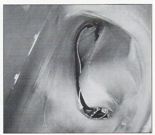
On the 18th they decided to have a second run with the aircraft restrained. A major incident occured when the engine suddenly stopped. On inspection in the intake ducts had collapsed and debris had entered the engine damaging the leading edge of the impeller. First thoughts were that the engine was ok and ducting had collapsed due to incorrect load distribution. It was stressed assuming there would be a 4psi pressure differential which was exceeded in practice... restressed for 12 psi, the duct was replaced with a heavier gauge one. On the 21st the night shift were shaken to discover a 3½ inch crack in the impeller. Close inspection determined that this was not as a result of the duct incident but was a failure due to a material defect.
De Havilland were working on a more robust impeller. The impellers were machined from great 'cheeses' weighing 500lb and at that time were the largest RR50 forgings to be made. The size meant that there were compromises on the material properties in the centre of the forging (shades of RB211 fan disc disintegration many years later) which were still there after the cheese was reduced to a 109 lb impeller. Wallace Devereux, the engineering brains behind High Duty Alloys, advocated controlling the silicon content of the alloy to less than 0.25%. This produced an impeller with acceptable properties throughout and, with the additional benefit of producing the alloy by continuous casting, a better cheese was produced.
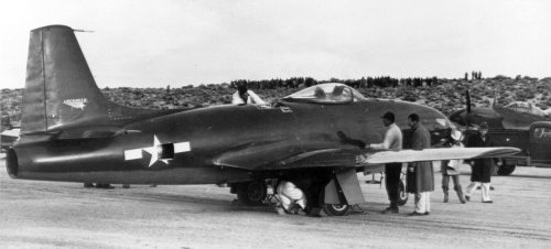
Obviously with so few Goblins around there was no spare easily available, nor spare parts as every part being made went to build a new engine, or replace a broken part. But the DH team were keen to help Kelly and by 27th agreed that a new engine could be shipped on Dec 11th to be in the USA by 15th. The damaged engine was shipped back to England. On 9th December disaster struck when the eleventh Goblin engine, which had been allocated to Lockheed, disintegrated on test! It was decided that swapping out an engine intended for the second Vampire was the best course and this could be shipped out by 22nd December 1943. It arrived at Muroc on the 29th Dec and was immediately prepared for installation. The next day it was statically tested and apart from minor adjustments was running well. New Year's Eve saw the engine run up to 9,600 rpm, the max cleared speed for flight. A well deserved day off followed and on 2nd January 1944 the tail was reattached and the aircraft readied for taxi trials on the 3rd. A day for inspection and then first flight on 5th were pencilled in. Kelly also signed off on most of the XP-80A proposal on that day. Kelly also decided that letting Muroc's test field dry out a day or two longer would also enable them to get all Skunk Works personnel up to witness the take-off so on 8th Milo Burcham, Lockheed's chief test pilot took it into the air for 6 minutes and on landing noted the landing gear would not retract... A fix was found and a second flight of 20 minutes followed.
The final picture shows the XP-80 being readied for its first flight with the Skunk Works team on the hill behind.
...tbc
 

Attachments

  • XP-80 milo burcham and kelly johnson-after first flight.jpg
    XP-80 milo burcham and kelly johnson-after first flight.jpg
    21.6 KB · Views: 95
  • xp-80-44-83020-02.jpg
    xp-80-44-83020-02.jpg
    126.1 KB · Views: 87
  • DH Goblin in XP-80 intake duct fails nov 18-1943.jpg
    DH Goblin in XP-80 intake duct fails nov 18-1943.jpg
    63.4 KB · Views: 86
  • DH Goblin in the XP-80 prototype.jpg
    DH Goblin in the XP-80 prototype.jpg
    185.1 KB · Views: 84
  • DH Goblin intake duct on the XP-80 prototype.jpg
    DH Goblin intake duct on the XP-80 prototype.jpg
    184.6 KB · Views: 76
  • DH Goblin first one arrives at Skunk Works.jpg
    DH Goblin first one arrives at Skunk Works.jpg
    86.7 KB · Views: 68
  • DH Goblin mockup in XP-80 mockup.jpg
    DH Goblin mockup in XP-80 mockup.jpg
    185.7 KB · Views: 73
I have often wondered whether contact with de Havilland - which had built the first Mosquito using an integrated, isolated and secure design-build team - had an influence on the original Skunk Works approach.
 
Good question... my gut feeling is that the two aircraft companies independently came up with a similar solution to a similar question... how do I keep a new project secret, away from people who might object to diversion of some of the best brains away from problems of war production?... both projects were not really accepted by the mainstream military decision makers. Although Lockheed had contact with DH engine personnel they [the DH engine people] may not have been aware of Mosquito activity.
In the end the [Lockheed] Skunk Works achieved a 143 day timespan for XP-80 airframe completion; only non-availability of engine prevented them achieving the 150 days to aircraft availability to fly. The beauty of Skunk Works is that they remove queuing, so contingency can be removed from the critical path...in a sense everything is critical! Dr Eli Goldratt in 1997 talked of the theory of constraints and the critical chain which roughly meant if you were an expert at 'x' and were required to give, say ten projects your attention, then you would be spread so thin that many would suffer as they waited for you to arrive. Health Services experience this!
So do aircraft project teams if they are in the main office.
 
Carrying on from #131:
As well as changing the material to low silicon RR50 aluminium alloy de Havilland also decided to test every impeller on an overspeed rig to check for soundness. The impellers were run at 15-20% over max rpm and then inspected for any evidence of faults. Also as the hours built up some impellers showed signs of fatigue cracking on the blades, which the team thought could be vibration-induced. Work started to investigate what excited the vibrations and what was the magnitude of any induced stresses. This involved working out how to attach strain gauges to the impeller, which had not been done before in such a highly loaded environment. It was soon established that the impeller had natural frequencies excited by the inlet arrangement:
The first was excited at 4x the engine speed, induced by the inlet arrangement, and
the second occured at 16times/rev. This was induced by upstream 'bow waves' from the shock of the air entering the 16 diffuser passages.
The first of these two 'exciters' was mitigated by moving the 4th order excitation (induced by the 4 intake radial vanes- see first picture) out of engine operating speed range- achieved by cutting back and chamfering the leading edge along its front entry part of the blade- raising the first flapping mode to higher frequency. A beneficial side effect was improved aerodynamic performance sufficient to allow a higher thrust and lower operating temperatures.
The bifurcated intake arrangement on both the XP-80 and the Vampire meant a circumferential temperature traverse of the jet exhaust exhibited wide temperature variations. By calibrating the fuel nozzles in each of the 16 cans, adjustments to fuel flow to each chamber could be made removing the hot spots around the traverse.By the end of January the flight tests had indicated flight handling mods necessary to improve the flyability of the XP-80. On 27th it was taken out of service and a whole list of mods incorporated. On the engine side the fuel flow modifications were incorporated.
Flight testing began again on 10th Feb 1944 when it made its 6th flight. The only glitch from an engine perspective happened during a ground run after flight 9- Feb 14th.- excessive heat was spotted on rear fuselage. Investigation revealed 2 stator blades had burned away. The burner in front of these blades had loosened, turned sideways and allowed excessive fuel into the can, generating excess heat. A locking device was devised and fitted on all burner nozzles, eliminating the problem.
A revised and improved engine cleared for 9,800 rpm was made available from Britain and fitted at the end of May. Unfortunately high tailpipe temperatures restricted running with the engine. On May 31st a restriction on rpm was placed on these engines, due to an explosion on test at DH. A few days later this was revised to a 9,500 rpm restriction. But the high jet pipe temperatures were still a nuisance as the hot summer approached.
By this time GE were promising production of the I-40 and so the XP-80A was designed around this engine.
Allis Chalmers never got really into licence-production with the Goblin.
 

Attachments

  • deHavilland Goblin-bifurcated intake and diffuser.jpg
    deHavilland Goblin-bifurcated intake and diffuser.jpg
    328.1 KB · Views: 87
Napier, Armstrong Siddeley and Bristol also got into the act a little later than RR and Metrovick. RAE had inspired an axial thread to the gas turbine development and being familiar with Metrovick had asked them to continue after the B10 rig. RR came in via a desire, partly altruistic, to get Whittle out of a pickle! Napier had its hands full with Sabre issues that had to be solved by throwing development and production expertise at it... namely Bristol and English Electric. Eventually the combination of taking over a DH project and using the experience from Nomad supercharging got them into the arena if not into the race. Bristol joined in the the 2nd GTCC meeting and realised the technology train was speeding out of the station so asked if they could get involved. Not wishing to duplicate work they decided their civil and bomber background should help in turboprop development so that is what they suggested to the Ministry. They got a contract to develop a turboprop and heat exchanger system. Armstrong Siddeley shook off the Griffith inspired route they were following and went for an axial turbojet, again trailing Metrovick. They could of picked up the F2 work at this stage but that meant collaborating with Metrovick which was culturally difficult so thay went for a trombone of a layout.
Although Griffith and Hayne Constant were axial advocates their scientific understanding had accelerated past their engineering capability to deliver and so even The small team at Power Jets showed a sound aero technology stretched hard could still win over a new one. Aero engines could not afford to let efficiency leak away like industrial applications, hence the hard time steam turbine firms had in the sky. Roxbee Cox and his backers were wiser souls with their technologies tempered in the heat of war so were more inclined to let firms that would regard the gas turbine as just another prime mover with a different set of problems to solve.
We'll follow their fortunes ............in the next few posts.
 
According to Bill Gunston,

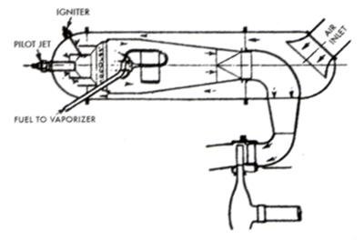
'An extremely important feature introduced hesitantly with the original (Armstrong Siddeley) ASX was the use of vapourising combustion. There are inherent problems with high-pressure atomising, but with the ASM system the fuel is sprayed at low pressure into a 'walking stick' 180 degree curved tube where it vapourises, not quite as in a blowlamp, to give near-perfect burning at all fuel flows, which can vary 100-fold between sea-level take off and high altitude flight idle'

'When Dr Stanley Hooker became Technical Director of the combined Bristol Siddeley firm in 1959 he found the ASM system superior to the more common scheme, and ordered it used on former Bristol engines.


Were there any other attempts at vapourising combustion?
 
Isaak Lubbock of Shell Labs was one of the team that solved the combustion problem on the Whittle turbojet. In Shell's words from their centenary brochure issued to commerate the 100th anniversary of Frank Whittle:

The Vaporising Problem

Sir Frank Whittle ensured that Britain entered the Jet age when, on 15 May 1941, the Gloster-Whittle E 28/39, propelled by of his jet engines, flew successfully from Cranwell, England.The Vaporising Problem

Shell had played an important part in this milestone with its answer to the combustion problems that the original Whittle WU engine had been experiencing. The solution was the “Shell” combustion chamber. Sir Frank once said: “The introduction of the Shell system may be said to mark the point where combustion ceased to be an obstacle of development”.

During the engine’s development, Sir Frank had worried about combustion problems because he was aiming for a combustion intensity more than 24 times greater than any other of that time.

Although a design for a vaporiser combustion system had already been developed, it proved temperamental as its coils either blocked with carbon or burnt out. Such problems were a major obstacle in the further development of the engine.

However, Isaac Lubbock, of the Shell Petroleum Company, was helping engineers from Power Jets – the Lutterworth company Sir Frank had formed to develop the turbojet engine – on combustion and fuel problems. Isaac invited the engineers to see a combustion chamber, similar to the size and form as the one being used in the engine. Shell engineers were also experimenting with the chamber in their laboratory in London.

[first pic]

The fuel was being injected into the chamber in a fine mist of liquid droplets through a controllable atomising burner. A Power Jets team saw it working in the laboratory and were impressed. They took it to Lutterworth where it was set up for Sir Frank to see.

After that, they concentrated their effort on the “Shell” combustion chamber, which was adapted to the engine. Another Shell expert, R. Joyce provided further assistance, developing the burner.
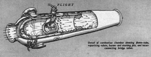
[second pic]


..................
The Armstrong Siddeley system built on the Whittle experience and overcame the shortcomings that had come to light on the Shell system as jets operated for longer hours and was of simple walking stick design first introduced on the ASSa3 engine. In fact they started straight away to develop Vaporisation which appeared on the ASX turbojet and was refined into the system used on the Mamba. Experience from that was eventually fed into the Sapphire ASSa3 in 1948, more or less as soon as they had full control of the programme. Seems pretty quick and bold to me. There is a Flight drawing that illustrates the design of the Python vaporiser. The Mamba picks up on the Sapphire design.
Why RR etc went a different way is another 'Arthur H. Lefebvre' story... the man who changed combustion on gas turbines for ever. He invented the air blast atomiser which gave good control of droplet size and hence predictable vaporisation behaviour in the main area of the chamber and allowed better control of the process for instance on the RB211 but that was way into the future... thank goodmness Hooker did not have the luxury of time to put the system on that engine in 1971.
 

Attachments

  • Armstrong Siddeley Mama CChamber section.jpg
    Armstrong Siddeley Mama CChamber section.jpg
    18.7 KB · Views: 594
  • Armstrong Siddeley Python CChamber sectioned.jpg
    Armstrong Siddeley Python CChamber sectioned.jpg
    214.9 KB · Views: 405
  • Armstrong siddeley hockey stick vaporiser as intro ASSa3.jpg
    Armstrong siddeley hockey stick vaporiser as intro ASSa3.jpg
    110.5 KB · Views: 412
  • combVapourizer-whittle-shell.jpg
    combVapourizer-whittle-shell.jpg
    12.1 KB · Views: 396
  • combustionChamber-original design for Whittle jet.jpg
    combustionChamber-original design for Whittle jet.jpg
    9.3 KB · Views: 395
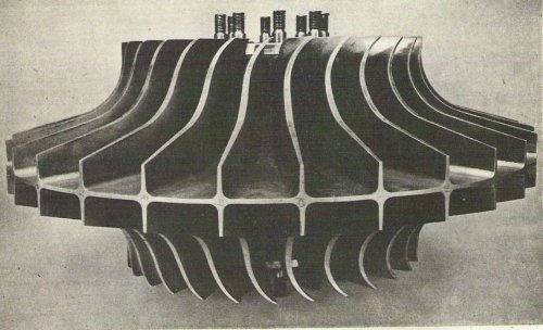
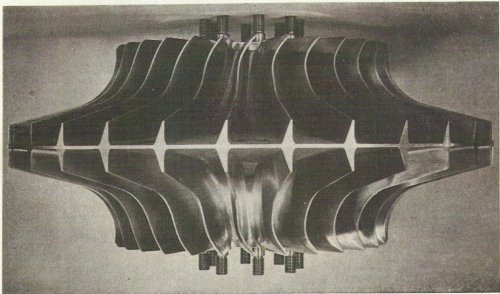
I mentioned above the failures of early Whittle impellers and the subsequent redesign to GE America design rules.. these cured the vibration induced failures of the impeller. I remembered reading about this in 1965 and finally found the report which contains a before and after picture. Basically the difficult machining challenge meant the first impellers had blades that were thicker at the eye than the tip... with induced vibration from the diffuser the tips flapped and cracked. GE for an entirely different reason adopted a thick tip approach and were better at machinng the impellers so they were thinner at the eye. This reversal of thickness changed the blade natural frequencies and the level of stress experienced so that the problem went away.
The two pics below show the change in design.
The pictures also show the curvature of the inlet rotating guide vanes; designers of this period used to assume that the rgvs were single stage compressor blades with a high camber. such a blade design exhibits flow break away and is therefore not the most efficient design. We have already noted how RR when scaling the Nene to the Tay increased the axial proportion of the rgvs to make the curvature less drastic, improving the aerodynamics of the design. Also on the Goblin changing the shape of the inlet edge of the rgv also improved the aerodynamic effectiveness.
 

Attachments

  • Whittle-early impeller design.jpg
    Whittle-early impeller design.jpg
    221.6 KB · Views: 361
  • Whittle-post GE-USA-impeller design.jpg
    Whittle-post GE-USA-impeller design.jpg
    218.6 KB · Views: 68
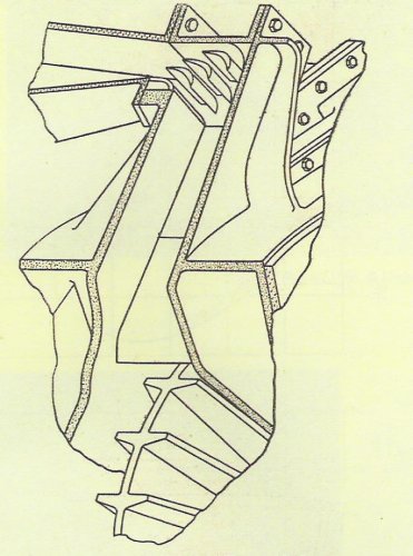
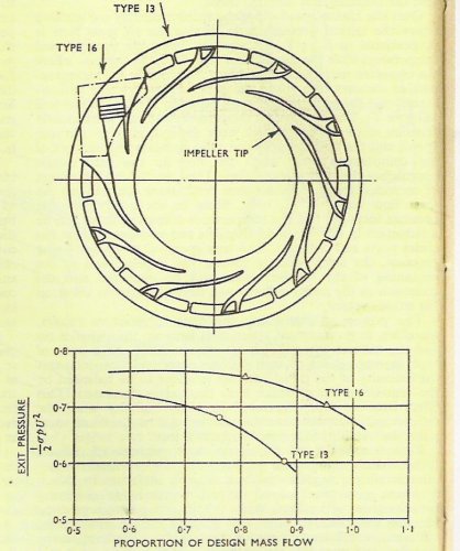
When Whittle moved from W1A development to the W2B he was keen to make the diffuser a little less bulky by reducing diffuser length from that shown in the first picture. The design team hit upon the idea of reducing the length whilst maintaining the angle of the walls by making 80 small diffusers working in parallel rather than 10 big ones. This lead to the 80 vane diffuser design at the bottom of the next picture. This was a disaster. Difficult to make uniformly, when fitted on the engine the result was surging that made the engine unable to accelerate... as we discussed above. A rapid reversion to the deign above the 80 vane on-known as Type 13 was rapidly developed on the new low-speed diffuser model rig. The rig enabled new shapes to be tried out at design mass flow and with uniform entry velocity (unlike the engine). It soon became clear that with vanes in the ductwhere the flow was turned to the axial direction not only could the flow be kept relatively smooth but some pressure recovery could occur. This led to the idea for a straight diffuser and then multivane passge for turning the flow.... the Type 16. Being easy to machine accurately this was rapidly adopted here and in the USA. The performance gain is shown in the graph - 3rd picture.
The Type 13 was fitted on the W2/500 and Type 16 on the W2/700. For reference I include a view looking on to the W1A vanes and an axial section of the W2B diffuser. the last pic is an isometric of the W2/700 diffuser.
Once Power Jets got a grip on the aerodynamics of the engine and with Hives, at RR, encouraging them they made good progress.
 

Attachments

  • Power Jets W2-700-isometric of Type 16 diffuser.jpg
    Power Jets W2-700-isometric of Type 16 diffuser.jpg
    113.9 KB · Views: 60
  • Power Jets W2B- axial section of diffuser.jpg
    Power Jets W2B- axial section of diffuser.jpg
    49.3 KB · Views: 51
  • Power Jets W1A-view on diffuser vanes.jpg
    Power Jets W1A-view on diffuser vanes.jpg
    35 KB · Views: 56
  • Power Jets Type 13 and Type 16 diffuser performance.jpg
    Power Jets Type 13 and Type 16 diffuser performance.jpg
    128.6 KB · Views: 59
  • Power Jets W2B- diffuser vanes-lower as 1st tested-upper most succesful 10 vane design.jpg
    Power Jets W2B- diffuser vanes-lower as 1st tested-upper most succesful 10 vane design.jpg
    134.1 KB · Views: 60
  • Power Jets W1A-isometric of diffuser.jpg
    Power Jets W1A-isometric of diffuser.jpg
    115.9 KB · Views: 71
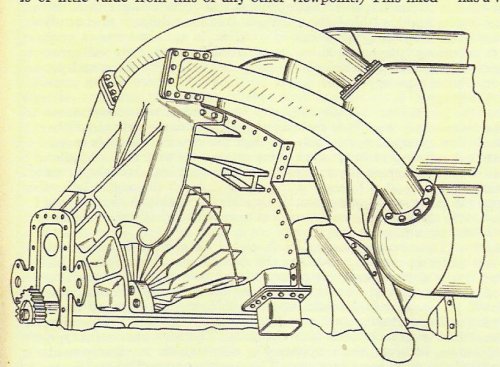
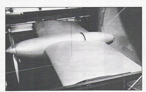
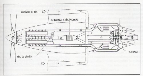
The french arm of Hispano-Suiza was drawn into the jetage when, after WWII, the Ministère de l'Air attempted to reinvigorate some of the stalled projects. As it was not clear that small aircraft would benefit from the gas turbine work was carried out under contract to the M. l'Air to develop a 36 litre piston engine based on the 12-Z engine .. a V12. This was the 12-B with a mechanical supercharger as normal and drove a propeller . The exhaust from the engine was lead to the rear and into a turbocharger turbine which drove a centrifugal compressor to supply the engine intake. A little like a Nomad n'est pas? The engine went to type test in 1951, but the engine never flew. 2nd and 3rd picture shows the design layout.
H-S was responsible for the overhaul of Merlin engines in France so had a good relationship with RR. This made them the choice of manufacturer when the French government decided to take a licence for the Nene. This made good sense as SNECMA were going down the route of developing German technology in the form of the ATAR.

H-S signed the agreement in Feb 1946 and began a long period of infrastructure development to support gas turbine production. It was June 1948 before the first Nene was rolled out of the H-S factory. Production finally ceased in 1955 after 1,073 were built. In 1950 a second licence was signed for the Tay. The first of Tay 220 engines which were built was delivered July 24th 1952. The licence fees were met from British-paid licence fees for the H-S cannon.
There were several versions of the Nene built in France starting with the 102; some prototype 103s followed which were lighter-the compressor casing was cast in magnesium, saving 176 lb for an engine weight of 1587 lb. So far the H-S engines were rated at 5,000 lbt. The six 103 development engines indicated some stiffening of the casing was necessary so the next version, the 104, had a thrust of 5,090 lb at a weight of 1609 lb. This version was the main production for the airforce and 771 units were delivered. The next version, the 105 had improvements in the flame tubes coupled with an improved starting capability. These changes gave a slight weight increase of 11 lbs and a thrust of 5103 lb.
The development team meanwhile had looked at how the thrust could be upgraded significantly and started on the development of the R-300 which used 50% Nene components but had H-S parts for the rest. This resulted in an engine weighing 1664 lb and delivering 5952 lbt. After 3 engines were built and tested the project was abandoned and the Tay went into production. Alongside all this and to help the SNECMA ATAR programme H-S built a reheat system for the Nene 102 first testing it in 1950. This R-400 version gave a 22% thrust increase The so called R-401 engine, based on the Nene 105, gave a thrust of 6790 lb for a weight of 2260 lb., preceeding the afterburning work at RR. After production ceased a batch of 200 engines to 104 or 5 standard were upgraded to a 106 which gave a thrust of 5,090 lbt for a weght of 1653 lb.
 

Attachments

  • Hispano-Suiza powerplant with 12-B-40 turbocompressor-nacelle wind tunnel model.jpg
    Hispano-Suiza powerplant with 12-B-40 turbocompressor-nacelle wind tunnel model.jpg
    182.5 KB · Views: 102
  • Hispano-Suiza powerplant with 12-B-40 turbocompressor.jpg
    Hispano-Suiza powerplant with 12-B-40 turbocompressor.jpg
    129.1 KB · Views: 107
  • H-S Nene with prototype afterburner.jpg
    H-S Nene with prototype afterburner.jpg
    121.9 KB · Views: 114
Having taken a Nene and developed a new variant the R-401, H-S again looked at doing the same sort of development of the Tay. This became the Verdon 350, with an rpm of 11,100 rpm up 100 from the Tay and a thrust of 7,710lb.for 2061 lb weight. Continuing to compare with the Tay, the massflow is 132 lb/sec vs 115; Pressure Ratio is 4.9 vs 4.0 (Nene was 4.3). The Verdon 450 is the ultimate afterburning version with a thrust of 9,920 lb.
....tbc
 

Attachments

  • rr_tay.jpg
    rr_tay.jpg
    39.9 KB · Views: 100
  • rr_verdon.jpg
    rr_verdon.jpg
    29.4 KB · Views: 87
  • H-S Verdon 350-side view.jpg
    H-S Verdon 350-side view.jpg
    82.3 KB · Views: 77
  • H-S Verdon 450 with afterburner-side view.jpg
    H-S Verdon 450 with afterburner-side view.jpg
    90.9 KB · Views: 74
As so many people have looked at the combustion aspects of the early jets in #137 I thought it worth pursuing the subject a little further. The James Clayton lecture delivered by Frank Whittle in 1945 is an excellent overview of the detailed development carried out by his team to travel from the technology demonstrator to a practical power unit i.e. from WU to W2/700.
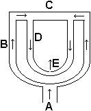
The early 10 chamber versions of the WU had vaporiser combustion chambers inspired by the Primus stove (sketch of principle : first attachment courtesy of Wikipedia)

The key for Sketch of the Primus stove burner head is
A: Connection to petroleum container;
B: ascending pipes carrying cold petroleum to the burner head
C: Burner head; D: Descending pipes carrying hot petroleum from the burner head to the nozzle;
E: nozzle and escaping hot petroleum ready to burn in the air.

So Whittle switched from diesel oil to kerosene and adapted the Primus principle to fit the ten combustion chambers (Type 31). The problem was the initial heating of the coils to start vaporisation and then stopping the engine from accelerating away due to accumulation of fuel during the light up process when the pilot injector was supplying a fuel mist. The robustness of the vaporising tubes was also in doubt so the team switched over to the Lubbock fuel spray nozzle and combustion chamber for the first W1A engines.
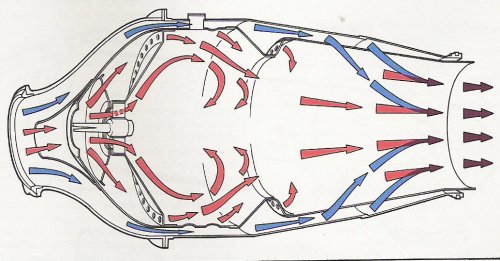
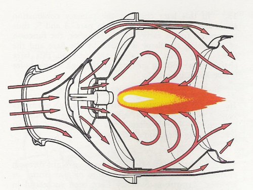
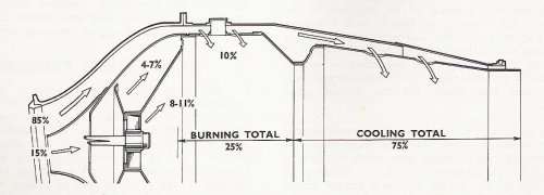
Using two sources of picture- RR's first edition of 'The Jet Engine' from the mis-50s and Power Jet's 1944 report CRN 371 we can build a picture of the early understanding of the combustion challenge. (see 3rd picture)
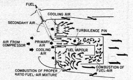
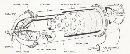
Just to refesh our memories the combustion chamber has 3 zones:
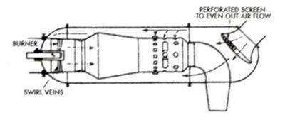
Primary: where the fuel introduction device and the ignition system resides. This zome is where most of the heat release occurs and where the maximum danger of local overheating of the metal parts. At the entry to the combustion chamber the air will be moving at around 80 ft/sec. As the kerosene flame front only moves at about 2 ft/sec we must do something to slow the air right down or the flame goes out (think lighting of flame to light a cigarette outdoors). So we need to swirl the air and create an inner zone of slow moving air (think eye of tornado). All this has to be achieved in a manner that anchors the flame in a stable manner (4th picture).
Secondary: when the main combustion action is nearly complete we need to introduce more air creating turbulence and mixing and supplying further oxygen to keep the reaction going. Bringing air in too soon will chill the flame and allow incomplete combustion and formation of soild products of combustion (e.g. carbon). The ability to achieve secondary mixing without too mach pressure loss has saprked a great deal of experiment on mixing devices.
Tertiary air has one function: to reduce the overall temperature to a level acceptable to the turbine. It is required to achieve a uniform temperature distribution at minimum pressure loss.
The overall airflow ends up looking like diagram 5.

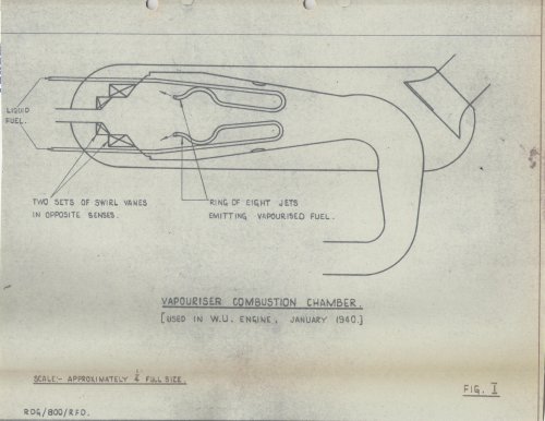
Returning to vaporisation; the idea is that the fuel is preheated by passing the fuel pipe through the flame and enters the combustion chamber as a vapour. The system offers the possibility of easy mixing and intense combustion. In (Whittle) practice it entailed great difficulties as the tubes burned out very easily and partial combustion was common in the tubes leading to soot formation in the tubes. Also the vaporisers need to be warmed up or stated before they will work sutainably which means providing a pilot spray jet to maintainn combustion until the tubes heat up. The pilot jet needs to be present in every one of the ten tubes on the W series engines. A typical chamber is in the next photograph
Given the difficulty of keeping the tubes in one piece the Whittle team looked around for a more robust solution the would keep going for the flight durations required, at the very least.
...tbc
 

Attachments

  • Whittle-vaporiser type 31.JPG
    Whittle-vaporiser type 31.JPG
    89.4 KB · Views: 72
  • general airflow pattern through chamber.jpg
    general airflow pattern through chamber.jpg
    113.8 KB · Views: 71
  • stabilising and anchoring the flame.jpg
    stabilising and anchoring the flame.jpg
    80.8 KB · Views: 63
  • apportioning the airflow.jpg
    apportioning the airflow.jpg
    61.8 KB · Views: 71
  • CRN371-May1944-Fig 1.jpg
    CRN371-May1944-Fig 1.jpg
    505.3 KB · Views: 71
  • Scheme_Burnerhead_Primus.JPG
    Scheme_Burnerhead_Primus.JPG
    5.5 KB · Views: 427
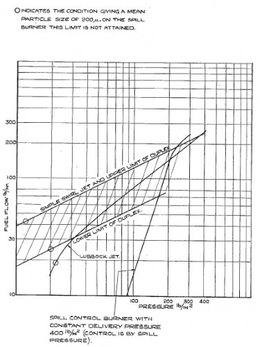
The square law pressure relationship iapplies to the atomisation of fuels. The Square Law relationship states ' the flow through the burner is proportional to the square of the pressure drop across it'. Bearing in mind that the flow range idle to max power is around 1:12 and if minimum pressure to maintain atomisation is 30 lbs/sq. in. then the pressure needed to give maximum flow can be as high as 5,000 b/sq. in- well above the pump technology of the time.
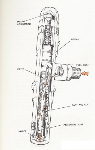
Shell and Lucas had both been drawn into the jet engine programme. Shell had a great understanding of combustion and Lucas of fuel delivery systems and sheet metal work. Isaac Lubbock and his assistant Geoffrey Gollin worked on the combustion chamber and came up with a possible design using A moving piston or Lubbock burner. (see the first attachment)
The Lubbock burner makes use of a spring-loaded piston to control the area of the inlet ports to the swirl chamber. At low flows the the ports are partly uncovered by the movement of the piston and at high flows and pressure the piston moves to fully uncover the ports. By this method the square law pressure relationship is mainly overcome and good atomisation is achieved over a wide range of fuel flows.
Whittle found that they could get away with a pump maximum pressure of 400 psi covered the operating envelope of the engine in 1944 but even then there was a small deterioration in atomisation at the lowest throughputs, which caused problems as the combustion chamber flows were very sensitive to small alterations in the spray angle. Due to the huge challenges of making the vaporisers reliable Power Jets switched to the Lubbock burner on all its engines; but again as the hours built up considerable trouble was experienced with sticking of the sliding piston due to dirt particles and with matching a set of burners; both inherent problems of the design, they proved impossible to overcome and the Lubbock burner was never put into production.
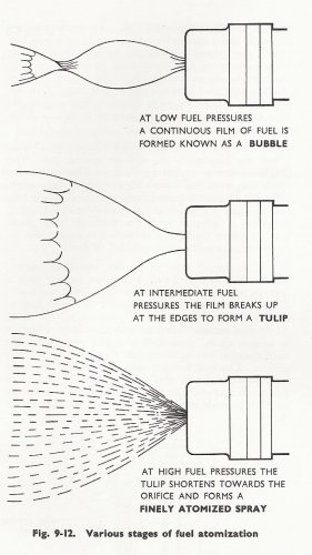
The Simplex burner has a simple cylindrical chamber with tangential slots to feed in the fuel and to induce a swirl and a fixed area atomising orifice. Used on the Derwent engine, it works well at high fuel flows but was very unsatisfactory at the low pressures required at low rpm and especially at high altitude. Hence the energence of the Lubbock design.
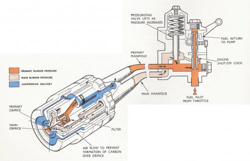
The inherent disadvantages of the Lubbock meant that the Lucas and Rolls-Royce combustion teams worked on other solutions, taking the Simplex as their starting point. This led to the Duple (RR) and Duplex (Lucas) design which had a swirl chamber with two independent metering orifices, one much smaller than the other. The smaller orifice handles thelower flows and the the larger orifice deals with the higher flows as the burner pressure increases. A pressurising valve is employed to apportion fuel through the two manifolds. At idling speed and at altitude, for example, the pressurising valve allows the fuel to pass the primary manifold and primary orifice only. As the pressure and flow increases, the pressurising valve moves to adnit fuel into the main manifold and the main orifices. in this way the ?Duplex and Duple burners are able to give effective atomisation over a wider flow range than the Simplex, and at altitude.
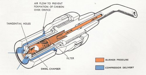
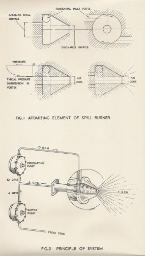
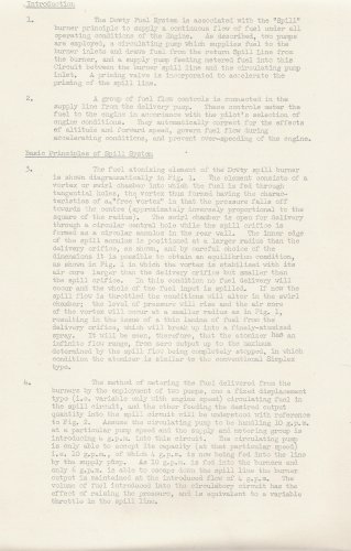
The Spill burner manufactured by Dowty is like a Simplex burner but with a passage from the swirl chamber for spilling fuel away. The pump delivers fuel at a constant, high, pressure and the flow out of the orifice is controlled by the amount of fuel spilled from the chamber e.g. as rpm reduces or altitude increases. The high pressure ensures good atomisation even at low flows. The spill burner system requires a second pump and controller to ensure starting, adjusting and stopping of the spill flow... see later post.
The graph shows the relative performance of various burners.
This leaves Air boost, air blast and upstream pencil nozzles.
 

Attachments

  • fuel flow vs pressure for various burners.jpg
    fuel flow vs pressure for various burners.jpg
    133.1 KB · Views: 74
  • duple burner and pressurising valve.jpg
    duple burner and pressurising valve.jpg
    175.5 KB · Views: 87
  • stages of fuel atomisation.jpg
    stages of fuel atomisation.jpg
    113.6 KB · Views: 71
  • Simplex burner.jpg
    Simplex burner.jpg
    108.3 KB · Views: 70
  • Lubbock burner.jpg
    Lubbock burner.jpg
    122.9 KB · Views: 78
tartle,
I think it's time to thank you very much for your contribution to keep this topic alive with lots
of material and especially explanations, that really give more understanding and insights into this not
really simple subject !
Keep it up ! ;)
 
Thanks for feedback...especially when it is positive.. I wish I had the knowledge I have now when I was an apprentice and talking to these people..Jim Boales was really interesting and happy to let me see his notes and reports... I wish I had known about Hispano Suiza and the Verdon as he would have filled me in on what went on there as he spent much time in France. His notes may have gone to RRHT... another research thread! Incidentally I reminded myself when I looked at my old lab works for the course at Cranfield that I actually did a testbed run on the vaporiser equipped Mamba!
 
Dowty made a good job of describing the spill burner principles in their technical manuals. I attach the relevant pages below.
 

Attachments

  • Dowty spill burner diagrams.jpg
    Dowty spill burner diagrams.jpg
    490.6 KB · Views: 82
  • Dowty spill burner description.jpg
    Dowty spill burner description.jpg
    530.3 KB · Views: 77
The realisation by Everybody involved in the Whittle jet engine programme that combustion was the achilles heel (as were Metrovick also) meant that Lucas, Asiatic Petroleum Company (as Shell were known back then), etc. were brought in to help.
A review of Power Jets efforts is summarised here in order to bring out the great amount of work done on the test bench in order to come up with a viable solution in the midst of a war!
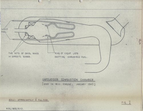
Power Jets review of combustion chamber (CC) design and testing states:
"From August 1939 to about the middle of 1940 a large number of vaporiser CCs were tried ...it would appear that combustion was fairly good when everything was working properly but the fuel system was extremely unreliable and the vaporiser tubes were liable to burn out or block up with carbon at any moment. The difficulty of obtainingan even distribution of fuel toall ten CCs, let alone to each of the fuel jets in a single chamber, was also a source of much trouble, the result being that some chambers ran much hotter than the others and the temperature distribution at the outlet of each chamber was also very bad. In addition to all these troubles, the problem of ignition was very great as a pilot jet had to be fitted into each chamber and kept alight until the vaporisers got sufficiently hot to start functioning. Starting, in fact, was an extremely critical matter as it was then that most of the burning out and blocking up occurred."

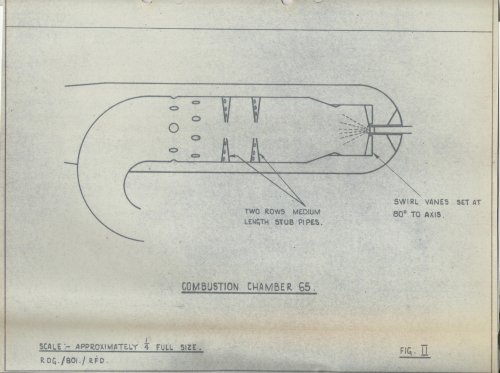
Fig 2 shows CC 65 which was the first to be fitted to an engine using a spray jet. It was a development of the chamber which was first designed by the Asiatic Petroleum Company to suit their Lubbock burner. It incorporated a multi-vane primary air swirler, a throat and two rows of stub pipes, while tertiary air was admitted through plain holes.
"It gave good combustion but the pressure loss was very high and the walls of the flame tube got extremely hot, so much so that even the air casings used to attain a dull red heat during running. It also gave a lot of trouble with Carbon formation and both the overheating and the carbon was believed to be due to the liquid fuel hitting the walls, the basic problem being a deficiency of primary air."

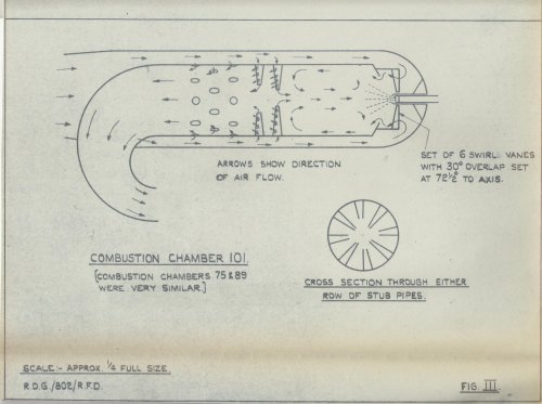
CC101 (fig 3): This chamber is the last of a family of flame tubes Nos. 75, 89 and 101, all of which incorporate a six-vane swirler, opposing conical throat and two rows of alternate long and short stub pipes. CC No 75 was the one employed on the first flights in May 1941 and is design incorporates a number of interesting features.
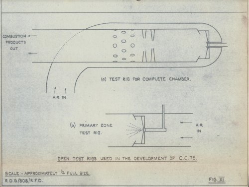
"Firstly, it was developed from the results of a large number of primary zone tests, well over 100 different combinations of swirlers and throats having been tested before any attempt was made to construct a complete flame tube. (Fig 11 is a diagram of rigs used)
These primary zone tests provided such valuable information and the result was that only minor modifications were required to the primary zone when the complete flame tube was tested.
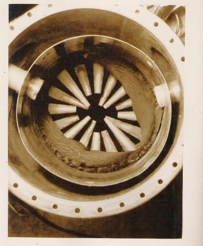
Secondly, the chamber provided some extremely interesting information on the subject of carbon formation. When it was first tried on the engine with long and short stub pipes, as shown in Fig 3, no coking trouble was experienced, but subsequent tests made with shorter stub pipes, invariably resulted in large carbon deposits which could only be got rid of by blocking up some of the tertiary air holes so as to increase the proportion of primary air. It eventually become evident that the long stub pipes were feeding air into the reversal zone and thus the effect of shortening the stub pipes was to reduce the amount of primary air, thus giving rise to carbon formation. The carbon was usually built up in the form of two strips, starting at the inter-connecting tubes and thence pursuing spiral paths down to the stub pipes where they merged into a thick ring all round the wall against the roots of the upstream stub pipes- see Fig 12."
"This chamber gave a fairly low pressure loss and high combustion efficiencies (over 95%)
at rich mixtures but the effeciency tended to drop off at mixtures weaker than 90:1 while some trouble was also experienced with the ends of the stub pipes burning off. An additional disadvantage was that the exhaust was slightly smoky with the result that the aircraft used to leave a trail of smoke in the sky. The smoky exhaust and the low efficiency at weak mixtures were probably both due to the amount of primary air having been excessive at all but the richest mixtures. this chamber, in fact, provides an excellent example of the advantages which would accrue if it were possible to vary the amount of primary air with mixture strength."
 

Attachments

  • An early Whittle chamber.jpg
    An early Whittle chamber.jpg
    131.1 KB · Views: 65
  • CRN371-May1944-Fig 12-coking up of CC89.jpg
    CRN371-May1944-Fig 12-coking up of CC89.jpg
    362.7 KB · Views: 65
  • CRN371-May1944-Fig 11.jpg
    CRN371-May1944-Fig 11.jpg
    533.7 KB · Views: 64
  • CRN371-May1944-Fig 3.jpg
    CRN371-May1944-Fig 3.jpg
    478.6 KB · Views: 64
  • CRN371-May1944-Fig 2.jpg
    CRN371-May1944-Fig 2.jpg
    535 KB · Views: 57
  • CRN371-May1944-Fig 1.jpg
    CRN371-May1944-Fig 1.jpg
    505.3 KB · Views: 65
The Power Jets report, published May 1944, states
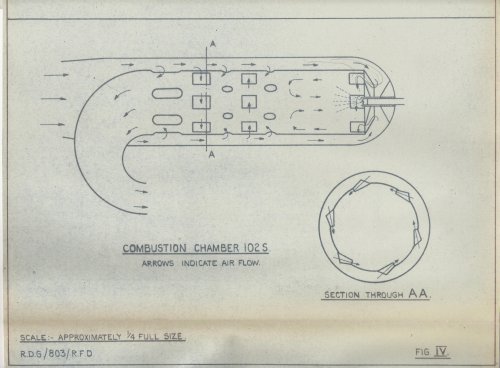
"CC102: This chamber is now standard on all PJ engines. Its essential feature (Fig 4) is the admission of primary air through tangential swirlers as opposed to multi-vane axial swirlers of the CC101. It also has the additional very great advantage of having no stub pipes or other projections which would be liable to burn out or form a nucleus for carbon formation.
Other features are:
1. The primary air is preheated by causing it to flow over the back plate, which gets fairly hot during running.
2. Part of the primary air forms a cool layer next to the walls and thus prevents the latter from getting overheated.
3. The air which is admitted through the first row of holes acts as primary air with rich mixtures but secondary at weaker mixtures, thus giving rise to higher efficiencies over a wider range of fuel/air ratios.
4. The admission of some of the secondary-tertiary air through two sets of tagential swirl ports in opposite senses promotes considerable turbulence and is a very effective mixing device."
 

Attachments

  • CRN371-May1944-Fig 4.jpg
    CRN371-May1944-Fig 4.jpg
    501.3 KB · Views: 60
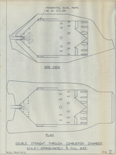
Another interesting design that did not see the light of day but confirms PJ's interest in straight thru' engine configurations was developed from CC102 with
".... the object of reducing total head loss by using 5 large CCs instead of the ten small ones and obtaining a greater volume of combustion space without increasing the length of chamber or engine diameter. The straight through design is approximately the same length as the W2/500 but max diameter is increased from 8 inches to 14, and there are two inlets to each chamber, the idea being to fit 5 chambers to an engine with the normal ten outlets from compressor. This design also tends to nullify the effects of non-axial airflow into the combustion chambers."
It is interesting to see that the same approach was adopted for the deH. Ghost engine.
 

Attachments

  • CRN371-May1944-Fig 5.jpg
    CRN371-May1944-Fig 5.jpg
    484.7 KB · Views: 59
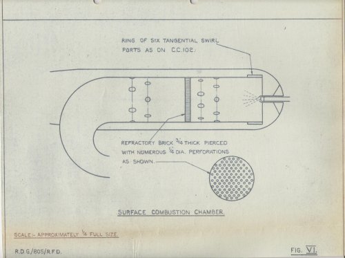
Another promising design that went nowhere was the surface combustion chamber. The idea is to 'throw' the fuel onto a very hot surface and the vaporising and burning to occur actually at this surface. The limitation which eventually led to abandonment was the lack of a material that would stay in one piece as it was subjected to the high thermal stresses caused during light up and shut down.
Silicon Carbide cement bricks were the best materials but still suffered from cracking and the risk of pieces breaking off and going through the turbine was too great to contemplate!
The chamber itself worked well with a very short flame but the tendency for carbon to build up on the surface when operating with rich mixtures was also a drawback.
 

Attachments

  • CRN371-May1944-Fig 6.jpg
    CRN371-May1944-Fig 6.jpg
    478 KB · Views: 457
It is interesting to note that vapourising combustion chambers are very popular today in micro gas turbines for model aircraft. To get around the coking issue such engines generally have to be run on propane during start-up until the vapouriser tubes have heated up sufficiently.
 
Just listened to a discussion programme that featured Frank 'I remember you' Iffield. His father invented a variable displacement pump that Lucas realised was just what was needed in a jet engine fuel system and employed him to make it happen.

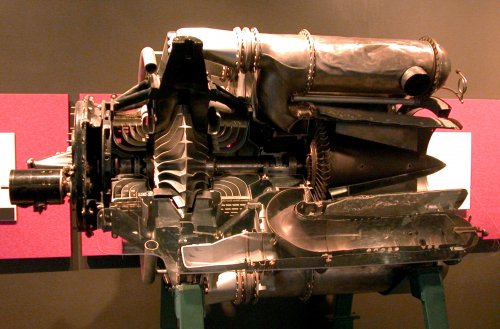
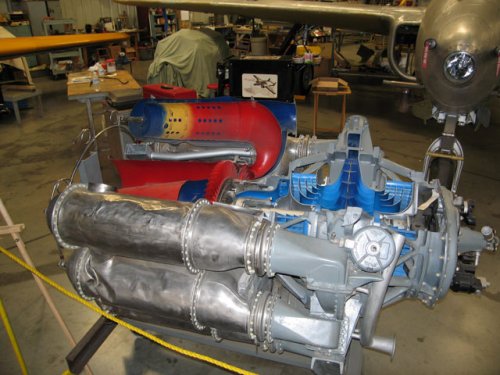
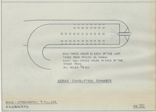
The last significant CC investigated at PJ was the NERAD CC, which was being developed by GEC of America. It is a very simple design and has air ports as simple circular holes - ideal for manufacture. The version tested at PJ gave good results under ideal conditions but was extremely susceptible to the slightest assymetry in airflow.
The most critical portion of the chamber was the first 2 or 3 holes downstream of the spray jet, as the position of these, in conjunction with the angle of the spray jet, controls the stability and, to a large extent, the performance of the chamber.
In the original report there is a comment "presumably much more work has been done in America, but the results are not known."
I thought I'd look at museum stuff to try and find an answer so found two engine pics.
 

Attachments

  • Yei16_1b.jpg
    Yei16_1b.jpg
    554.9 KB · Views: 686
  • ge_j31.jpg
    ge_j31.jpg
    85.7 KB · Views: 678
  • CRN371-May1944-Fig 7.jpg
    CRN371-May1944-Fig 7.jpg
    380.4 KB · Views: 735
Last night I was giving a lecture on Maurice Egerton, friend of Charlie Rolls of RR fame and his pioneering flying effirts in the Edwardian era.. one of his engines was a Gnome rotary.. a meber of the audience remarked how other people had tried rotaries but it was the Seguin brothers who put the right technologies together and 'conquered the world'. The reason I have shared my studies is apart from the fun of it is to help my understanding of why these factors are relevant now and what technologies allow us to make a better job of it than, say PJs did.
RR has stated:
"Engine 3E being developed by RR in Germany has basic project requirements in principle can be separated into two categories: performance and business related requirements.
Traditionally, the performance related requirements such as emissions and combustion efficiency are in the main focus in the beginning of the technology development whereas the business related requirements such as life, weight and cost set in when the initial concept is demonstrated.

The project requirements are broken down into the following sub-system requirements:
• NOx: <35% CAEP2, CO: <60% CAEP2, UHC: <40% CAEP2, invisible smoke
• combustion efficiency comparable to current in-service (rich burn) combustion systems, maximum efficiency at part power conditions
• cold starting down to -40° C SLS, altitude relight > 25 kft, reasonable pull-away time to idle
• combustion stability during transient operation and hail & rain conditions: sufficient margin against lean blowout (LBO) at flight idle
• temperature traverse meeting turbine requirements
• component life: fuel injector thermal management, combustor cooling
• high reliability, robust design
• weight, cost

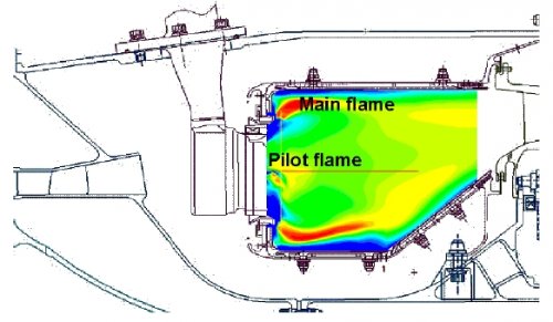
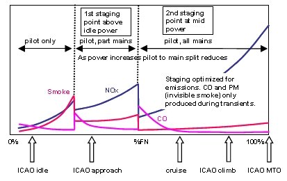
In a first step, the combustor volume was determined according to conventional design rules. Fuel mixing and staging is accomplished within the fuel injector configuration of concentrically air swirlers . The internally staged fuel injector operates in a pilot and main mode depending on engine power.
As most of the combustor air flow within a lean burn combustor is required for fuel preparation within the fuel injectors the combustor wall cooling air split was reduced by the introduction of a double skin wall arrangement, where heat resistant tiles attached to the combustor liner are taking the thermal load. The liner absorbs thermal stresses and ensures structural integrity. The split of the combustor wall into two components with individual functions enables the optimisation of material selection for both components. The tile cooling is accomplished by an impingement effusion scheme [definition: Effusion cooling uses cool fluid to create a cool fluid region between hot free-stream gasses and the wall. There are currently two types of effusion cooling: film cooling and transpiration cooling.], where air impinges onto the cold side, flows through an array of holes and exits on the hot side as a cooling film.
The specific challenge for a lean burn combustor constitutes the integration into the core environment. Due to the shifted air distribution towards the fuel injector a stronger interaction between the combustor/compressor and combustor/turbine can be expected. The OGV-diffuser design must take into account the downstream pressure distribution resulting from high air flow fuel injectors. The HP turbine design has to cope with a flatter temperature distribution, e.g. lower relative temperatures at blade mid height and higher temperatures at root and tip. In addition, the residual swirl also needs to be considered during the HP NGV design. The major objective of an internally staged lean burn fuel injector is to generate a homogeneous fuel-air mixture in a
given combustor volume allowing for combustion at reduced peak temperatures at medium to high power operating conditions. This is accomplished by a fuel injector with concentrically arranged main fuel stage surrounded by swirling air streams carrying the main portion of air and a nested pilot fuel injector located in its centre.
As the available mixing length in a combustor is limited, the initial fuel preparation process is critical. The main fuel injection is realised with a pre-filming air-blast concept. Within the prefilmer fuel is distributed over a surface area resulting in a thin fuel layer exposed to air with high velocity. As a result the fuel sheet disintegrates into fine droplets being dispersed and evaporated downstream. This concept becomes more challenging for larger fuel nozzles due to the unfavourable fuel to surface ratio (loading). The fuel rich pilot stage is required for low power operation and stabilization of the main stage maintaining full combustor turn-down ratios for operability. This is important especially for transient manoeuvres during adverse weather conditions such as hail and rain. Two basic fuel injection techniques were investigated for pilot injection: pressure and air blast atomization. The first one features a relative simple design and hence lowers costs. The latter is more complex allowing for a better specific control of fuel air
mixing. Thermal management schemes are implemented into the fuel injectors to control fuel wetted wall temperatures.

The specific fuel scheduling requirements are realised with individual fuel manifolds and a splitting unit delivering fuel to the individual fuel injector groups as a function of the engine thrust. Adequate control laws are implemented into the EEC software taking into account emissions and operability requirements."
 

Attachments

  • E3E combustor.jpg
    E3E combustor.jpg
    137.8 KB · Views: 662
  • lean burn staging scenario.jpg
    lean burn staging scenario.jpg
    59 KB · Views: 344
And just when you thought Griffith's ideas were long gone:
Volvo's contribution to concepts for the European funded NEWAC programme:
Description
The benefit of a variable core cycle comes from the raised thermal efficiency of the core at cruise phase. One idea to achieve this benefit is to utilize a stator-less high pressure turbine (HPT) and high pressure compressor (HPC) variable guide vanes (VGV). The corrected mass flowing into a stator-less HPT is dependent on the rota-tional speed. By controlling the angle of the VGVs, shaft speed and core mass flow can be varied. This affects the pressure ratio and thus also the thermal efficiency.
Stator-less HPT alone has limited power output. Meanwhile, it creates undesired large amount of outlet swirl. To overcome these problems, a stator-less, counter-rotating turbine is utilized. This turbine drives a compressor whose front part is con-ventional while the rear part is counter-rotating. Such a compressor distributes the power consumption more to the second turbine. Also, more variable guide vanes can be used at the front stages of the compressor to improve the part-load efficiency.
Benefits
• Increased thermal efficiency at cruise phase
Technology Readiness Level: System 3 (theoretical evaluation); Components 2+
Risks
• Design of a working cooling system
• Amount of fuel saving
• Requirement on profile for mission thrust/speed/altitude
Application: Commercial aero engines

-------------
The ngvaneless idea was incorporated in the XJ99 liftjet.
 

Attachments

  • variable core technology.jpg
    variable core technology.jpg
    94.8 KB · Views: 91
Armstrong Siddeley were involved fairly early in the gas turbine story, having been asked to build the rig to test out Griffith's contra rotating turbomachinery concept. #47 gave details of the testing of this rig. Fritz Heppner at A-S went on to design the A S H contra rotating engines....
Once the firm realised the challenges of the contra route they decided to get into the mainstream activity of the GTCC. At the time of their interest the main activity apart from Metrovick's was aimed a single and double sided centrifugal compressor designs. To stand a chance of competing and to build on their relationship with RAE they decided to look at an axial design. The best design at RAE, so far, was the Freda design. A-S thought a higher pressure ratio might now be obtainable and went for such a target. RAE calculated and schemed a fourteen stage compressor consisting of the existing Freda spool (9 stages) with a new design 5-stage spool bolted on the front. The new spool had blading designed on similar principles to Freda but with the assumption of constant reaction rather than free-vortex (reaction increasing with radius). Explanation of the theory we'll do outside of this post!

The design conditions of Freda and Sarah are tabled below:-

Freda Sarah

Mass flow lb/sec 50 50
Pressure Ratio 4:1 6:1
Rpm 7,390 8,000
Number of stages 9 14
Max tip speed ft/sec 718 714
Mean axial velocity ft/sec 500 490
Tip diameter, in 22.2 20.5
pich/chord ratio
mean 1.24
root 0.68
tip 0.9

The blade profile was RAF 27 setout on a circular arc backbone with a mean t/c ratio of 13% on Freda. On Sarah a consequence of the design vortex distribution is that for a given tip Mach Number the root Mach Number will be greater so a smaller root t/c ratio is used , for a given blade thickness this is achieved by increasing chord length, which increases stage weight; it is a balancing act weather the extra work input done at the root and subsequent greater pressure rise allows a shortening of overall compressor (less stages) to offset the weight gain. Another option is to increase the aspect ratio which will put up blade numbers per stage as the space/chord ratio will have to be maintained for aerodynamic reasons. Bear in mind that, for manufacturing reasons, the Metrovick F2 had the same number of blades and vanes throughout the compressor. In a free vortex design the staor vanes have little or no twist. The same vanes were used throughout and the tips were trimmed for each stage, Similarly the blades were the same throughout and again the tip was trimmed to fit. We mentioned elsewhere in this thread that HDA and MV had come up with a new pressing process to make the aerodynamic form which was very consistent blade to blade, vane to vane. This also helped make Freda so efficient as a compressor.
The pictures of the ASX rotor and stator casing clearly show the constant Overall diameter of the new LP stages and constant hub diameter of the existing Freda HP stages as they were referred to at the time.
Experience with the annular combustion chamber had by this time highlighted how difficult that section of the engine was; feedback on the tribulations of the early Whittle work was also available. Two other factors- keeping the overall diameter down and minimising engine length also played out in the configuration chosen. Minimising length led to the adoption of the reverse-flow axial equivalent of the Whittle engines... and the long slim combustion chambers are really a consequence of this and diameter minimisation.
Having been awarded a development contract in Nov 1942 A-S managed to have the first engine on the test bed by April 1943.. a sign of how much they 'borrowed' from the RAE and the fact they were not as heavily committed to war work as RR, Bristol and Napier were. Those first runs yielded a thrust of 800 lb, well below the design performance of 2,550 lb which was soon achieved in September wit h an sfc of 1.0.
Flight testing followed in the Lancaster Universal Test Bed and by 1944 2,800 lbt was acieved but at a weight of 1,900 lb... not very inspiring. One good development came out of it. The Vapourising CC. Originally equipped with a Lucas CC with spray nozzles the idea of Whittle's vapourisng system seemed very attractive and so they decided to pursue that route. By 1945 they had combustion test rigs running and had fitted the system to one of the ASX engines. Flying it in the Lancaster enabled them to test the engine up to 35,000 ft altitude with good slow running and reignition performance. As we saw on the PJ engines the system eliminated the need for high pressure pumps and was reliable over the whole flight envelope.
It was decided that possibly a way out of the low performing turbojet issue was to go for a turboprop conversion.. and so the ASP was born.
 

Attachments

  • raf27.gif
    raf27.gif
    11.3 KB · Views: 61
  • Armstrong Siddeley ASX stator.jpg
    Armstrong Siddeley ASX stator.jpg
    95.6 KB · Views: 55
  • Armstrong Siddeley ASX rotor.jpg
    Armstrong Siddeley ASX rotor.jpg
    82.2 KB · Views: 76
  • Armstrong Siddeley ASX section.jpg
    Armstrong Siddeley ASX section.jpg
    24.4 KB · Views: 83
OT: Modern British gas turbine development


Contra-rotating turbine technology[/size] has advantages in pre-cooled engines both for advanced launchers and for hypersonic civil transport when an air compressor is driven by a helium or hydrogen turbine (giving a large speed of sound mismatch between the turbine and compressor).

http://www.reactionengines.co.uk/contraturbines.html
 
It is all about the velocity triangles. The RB189/XJ99 had contra rotating blades for the turbines... worked well with ordinary kerosene/air charges too. The turbine designed at VKI uses the different qualities of working fluid to do proof of concept with cheap materials operating at appropriate stresses.. very interesting.. thanks for pointing it out. The reaction engines stuff is about an engine for a 2 hour flight London-Sidney or Paris-Sidney (european project) .. another thread I think?
 
This evening as I was passing the MOSI building that houses the aviation collection, I thought it might be possible to photograph the F2 compressor blades to show the free vortex design. DSC01584g.jp shows the whole set of blading for the nine stages. We can also see the straight stator vanes in the lower casing. DSC01585-87.jpg show close ups of the blading.
 

Attachments

  • DSC01587.JPG
    DSC01587.JPG
    576.4 KB · Views: 63
  • DSC01586.JPG
    DSC01586.JPG
    552.5 KB · Views: 43
  • DSC01585.JPG
    DSC01585.JPG
    614.7 KB · Views: 55
  • DSC01584.JPG
    DSC01584.JPG
    570.6 KB · Views: 61
I also did a quick session on the W2/700 at MOSI....

the first picture is a general view of the engine focussing on the parts we have been discussing.
The second photo shows the impeller as discussed in #128
The third shows the diffuser; as we discussed in #139 it is easy to machine accurately and the turning vanes can be slotted in very easily.
The fourth and fifth pictures show CC102 that we discussed in #148.
I hope the visuals help flesh out the descriptions.
 

Attachments

  • DSC01593.JPG
    DSC01593.JPG
    597.2 KB · Views: 59
  • DSC01592.JPG
    DSC01592.JPG
    514.7 KB · Views: 57
  • DSC01591.JPG
    DSC01591.JPG
    511.9 KB · Views: 58
  • DSC01590.JPG
    DSC01590.JPG
    523.4 KB · Views: 62
  • DSC01589.JPG
    DSC01589.JPG
    569.7 KB · Views: 90
Fortunately Armstrong Siddeley had on its books an excellent Gear Design Engineer called Norman Barcham, who designed a gearbox to transmit the power to an airscrew; the extra power required to drive the airscrew being provided by redesigning the existing two-stage turbine for increased work.... one reason the jet was heavy was because the components were conservatively or underdesigned in the first place...this is the ASP
The ASP engine, eventually named Python, first ran in April 1945 and eventually delivered 3,600 shp and 1,100 lbt for a weight of 3,450 lb. The Clyde delivered around 4,000 shp and weighed 2,800 lb and had scope to deliver even more power with an additional turbine stage. The Python after a protracted development period gave around 4,000 shp at 3,505 lb weight. It was really only put into production because Hives would not sanction Clyde production.
The NAewis Altitude Wind Tunnel was a unique facility and their archive states:
"In response to a NACA request, the British supplied a Armstrong-Siddeley contra-rotating turboprop engine to study in the Altitude Wind Tunnel These tests from July 1949 through January 1950 were the first time the tunnel was used to study an engine with the sole purpose of learning about, not improving, the engine."
The first photograph taken 25/8//1945 is captioned:
"An engine mechanic checks instrumentation prior to an investigation of engine operating characteristics and thrust control of a large turboprop engine with counter-rotating propellers under high-altitude flight conditions in the 20-foot-diameter test section of the Altitude Wind Tunnel at the Lewis Flight Propulsion Laboratory of the National Advisory Committee for Aeronautics, Cleveland, Ohio, now known as the John H. Glenn Research Center at Lewis Field."
The second photo is captioned:
"The dynamic response of the British Armstrong-Siddeley Python contra-rotating turboprop engine was studied in the Altitude Wind Tunnel using a frequency-response method at altitudes of 10,000 to 30,000 feet. Using four different tailpipe arrangements the Python's static and dynamic performance characteristics were also studied at 10,000 to 40,000 feet and engine speeds of 6800 to 8000rpm."
 

Attachments

  • AS-Python cutaway.jpg
    AS-Python cutaway.jpg
    380 KB · Views: 136
  • 2262.jpg
    2262.jpg
    250.3 KB · Views: 129
  • 2259.jpg
    2259.jpg
    249.5 KB · Views: 118
  • AS Python diag in Lewis awt.jpg
    AS Python diag in Lewis awt.jpg
    55.6 KB · Views: 128

Similar threads

Please donate to support the forum.

Back
Top Bottom