- Joined
- 24 November 2008
- Messages
- 1,549
- Reaction score
- 2,606
XY: "A stealth fighter in the size of a Saab Gripen is impossible without compromising its performance to a point where it becomes useless".
Me: "Hold my beer..."
Everyone is welcome to join! But be aware, this is intended to be beyond napkin sketches. You may need some CAD skills or access to design software to be able to model complex geometries like serpentine ducts and to estimate your vehicle parameters, like fuselage volume, fuel tank volume, etc. However, it all starts with a sketch and you are welcome to post your ideas!
A discussion on the feasibility of a small stealth fighter started in this thread: https://www.secretprojects.co.uk/th...o-stealthy-combat-aircraft-designs-get.37600/
Check it out. It provides some good information. Please avoid general discussions on the usefulness of a small stealth fighter and the like in this thread. This is a design challenge!
So, where to start?
I use the specs of the legacy Saab Gripen “L” as a reference and those of the new generation “NG” as the threshold:
Lenght: 14,1m / 15,2m
Span: 8,4m / 8,6m
Wing Area: 25,5m² / 31m²
Empty Weight: 6600kg / 7600kg
Fuel Capacity: 2800l (2300kg) / 4200l (3400kg)
It is reasonable to assume internal weapon bays and complex serpentine air intake ducting will decrease fuselage volume available for fuel, while increasing the empty weight (in comparison to a traditional design). Consequently, I assume an empty weight more towards the NG (7600kg), while considering a fuel tank capacity more in the region of the L (2300kg), to keep the fuselage volume within reasonable margins (cross section / length).
I think that's reasonable assumptions to start with. However, modern production technologies may allow the weight growth to be smaller. How much fuel tank volume is indeed achievable will be seen in the end of the design process... In any case it's quite clear that the desired LMF must use the GE F414 engine, as installed in the NG.
What's next?
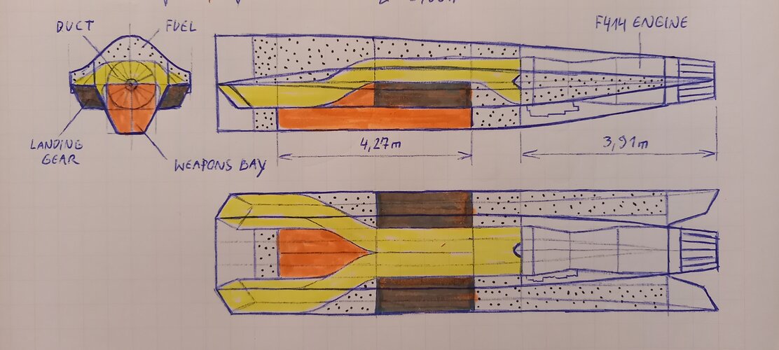
To get an idea of the internal volume required I decided to start with a fuselage cross section drawing. It is basically determined by three items (*four):
1) the engine diameter
2) the weapons bay
3) the engine air intake ducting
...AND not to forget 4) the main landing gear!*
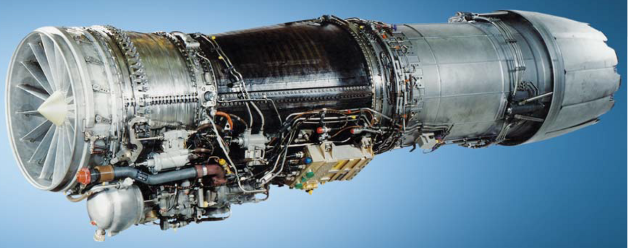
ad 1): The F414 engine's intake diameter is given with 0,79m, maximum diameter 0,89m. Not to forget the accessories attached to the bottom of the engine require some space as well. The length of the engine is given with 3,91m.
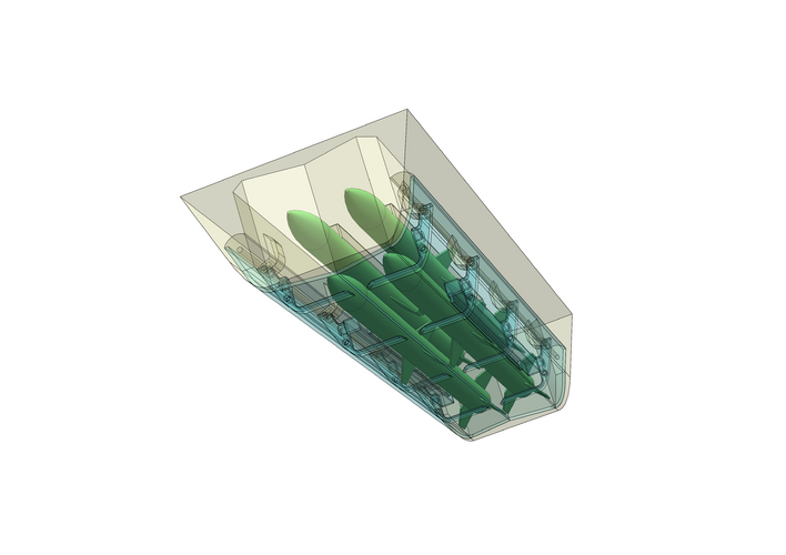
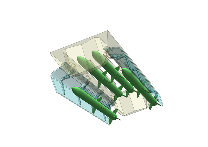
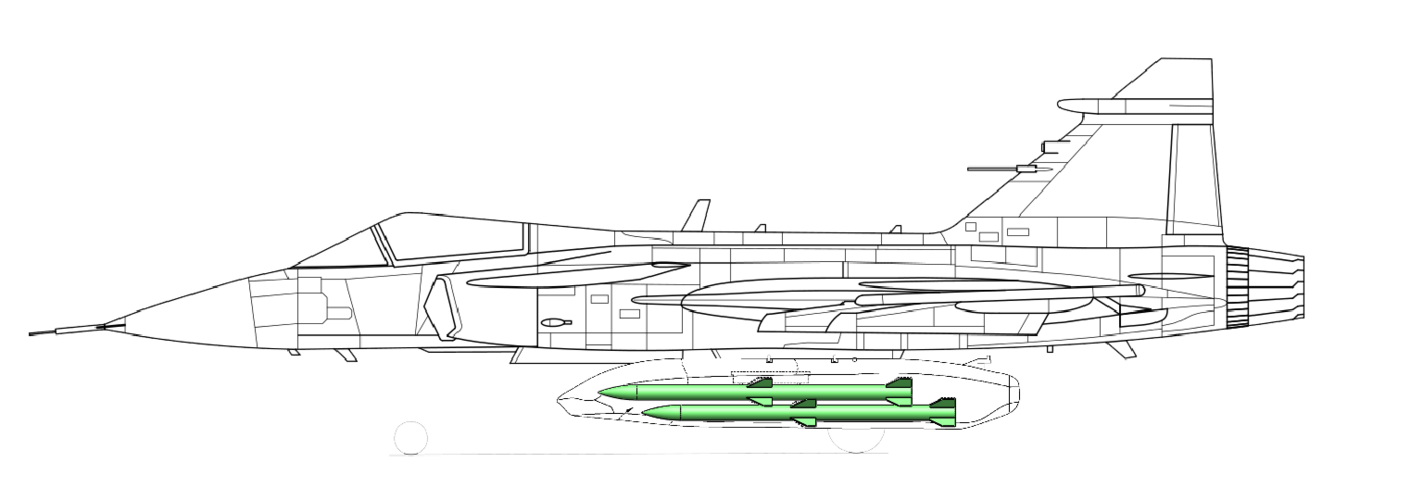
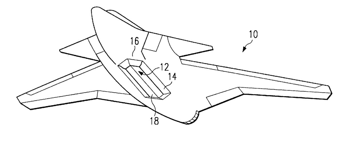
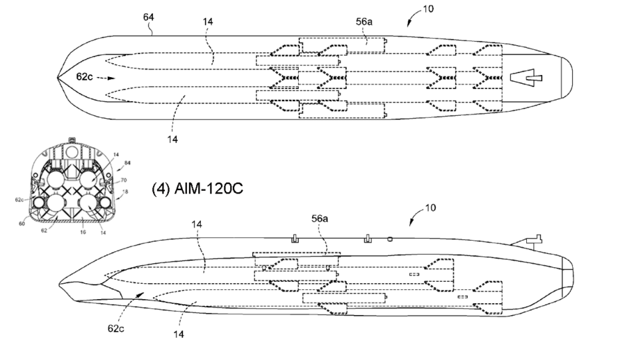
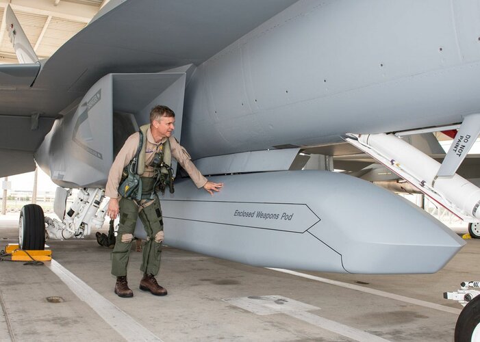
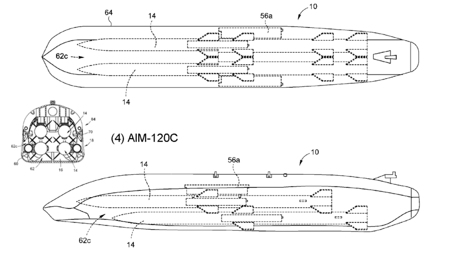
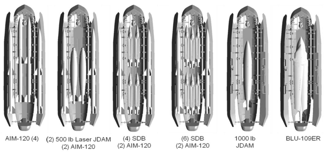
ad 2): After some initial sketching of fuselage cross sections Boeing's Enclosed Weapons Pod (EWP) came to my mind... It accepts four AIM-120 (C) and is actually a quite compact and versatile package. Luckily a patent including detailed line drawings is available. I decided to use the EWP as a baseline to size the internal weapons bay of my LMF concept.
AIM-120C:
Length: 3,66m
Diameter: 0,178m
Wingspan: 0,474m
ad 3): The F414's intake diameter results in an intake area of 0,49m². Obviously one or two air ducts with a continuous duct cross section must be routed through the fuselage from the intake(s) to the engine's mouth. Serpentine ducts are mainly a geometrical challenge. I came to the conclusion that routing it on top of the weapons bay is most likely the best solution. However, the question what kind of air intake will be used remains open at this stage. A dorsal inlet was ruled out from the onset. It would be the best solution to avoid a long serpentine duct penetrating the fuselage, but I consider it as not applicable due to the lack of practical examples (in highly manoeuvrable supersonic fighter jets).
ad 4): To be honest, I forgot to account for main landing gear compartments in my first considerations Actually a quite important item and not easy to integrate in addition to the weapons bay and serpentine ducts (without making the aircraft fat).
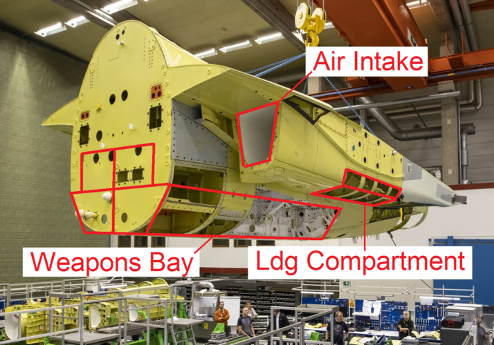
Since I've already decided to use a central single "EWP-style bay" a centralized landing gear compartment is not applicable (e.g. F-16). Furthermore, Boeing's EWP features doors that swing to the sides. That prohibits the use of side intakes that go all the way to the bottom of the fuselage (e.g. F-22).
Ultimately I came to the conclusion that it is most efficient to hide the main landing gear behind trapezoid side intakes. Kind of a “stealthified” version of Tornado or Jaguar intakes. The long serpentine duct going all the way through the fuselage required by chin intakes made me decide against it. I also wanted to avoid the landing gear to retract into the wing, which would result in extra-long landing gear legs (e.g. X-32).
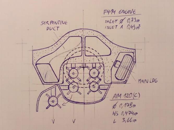
The attached sketch illustrates the basic concept I’ll use. Actually the cross section of Boeing’s T-7A Red Hawk is very similar To be continued...
Me: "Hold my beer..."
Everyone is welcome to join! But be aware, this is intended to be beyond napkin sketches. You may need some CAD skills or access to design software to be able to model complex geometries like serpentine ducts and to estimate your vehicle parameters, like fuselage volume, fuel tank volume, etc. However, it all starts with a sketch and you are welcome to post your ideas!
A discussion on the feasibility of a small stealth fighter started in this thread: https://www.secretprojects.co.uk/th...o-stealthy-combat-aircraft-designs-get.37600/
Check it out. It provides some good information. Please avoid general discussions on the usefulness of a small stealth fighter and the like in this thread. This is a design challenge!
So, where to start?
I use the specs of the legacy Saab Gripen “L” as a reference and those of the new generation “NG” as the threshold:
Lenght: 14,1m / 15,2m
Span: 8,4m / 8,6m
Wing Area: 25,5m² / 31m²
Empty Weight: 6600kg / 7600kg
Fuel Capacity: 2800l (2300kg) / 4200l (3400kg)
It is reasonable to assume internal weapon bays and complex serpentine air intake ducting will decrease fuselage volume available for fuel, while increasing the empty weight (in comparison to a traditional design). Consequently, I assume an empty weight more towards the NG (7600kg), while considering a fuel tank capacity more in the region of the L (2300kg), to keep the fuselage volume within reasonable margins (cross section / length).
I think that's reasonable assumptions to start with. However, modern production technologies may allow the weight growth to be smaller. How much fuel tank volume is indeed achievable will be seen in the end of the design process... In any case it's quite clear that the desired LMF must use the GE F414 engine, as installed in the NG.
What's next?
To get an idea of the internal volume required I decided to start with a fuselage cross section drawing. It is basically determined by three items (*four):
1) the engine diameter
2) the weapons bay
3) the engine air intake ducting
...AND not to forget 4) the main landing gear!*
ad 1): The F414 engine's intake diameter is given with 0,79m, maximum diameter 0,89m. Not to forget the accessories attached to the bottom of the engine require some space as well. The length of the engine is given with 3,91m.
ad 2): After some initial sketching of fuselage cross sections Boeing's Enclosed Weapons Pod (EWP) came to my mind... It accepts four AIM-120 (C) and is actually a quite compact and versatile package. Luckily a patent including detailed line drawings is available. I decided to use the EWP as a baseline to size the internal weapons bay of my LMF concept.
AIM-120C:
Length: 3,66m
Diameter: 0,178m
Wingspan: 0,474m
ad 3): The F414's intake diameter results in an intake area of 0,49m². Obviously one or two air ducts with a continuous duct cross section must be routed through the fuselage from the intake(s) to the engine's mouth. Serpentine ducts are mainly a geometrical challenge. I came to the conclusion that routing it on top of the weapons bay is most likely the best solution. However, the question what kind of air intake will be used remains open at this stage. A dorsal inlet was ruled out from the onset. It would be the best solution to avoid a long serpentine duct penetrating the fuselage, but I consider it as not applicable due to the lack of practical examples (in highly manoeuvrable supersonic fighter jets).
ad 4): To be honest, I forgot to account for main landing gear compartments in my first considerations
Since I've already decided to use a central single "EWP-style bay" a centralized landing gear compartment is not applicable (e.g. F-16). Furthermore, Boeing's EWP features doors that swing to the sides. That prohibits the use of side intakes that go all the way to the bottom of the fuselage (e.g. F-22).
Ultimately I came to the conclusion that it is most efficient to hide the main landing gear behind trapezoid side intakes. Kind of a “stealthified” version of Tornado or Jaguar intakes. The long serpentine duct going all the way through the fuselage required by chin intakes made me decide against it. I also wanted to avoid the landing gear to retract into the wing, which would result in extra-long landing gear legs (e.g. X-32).
The attached sketch illustrates the basic concept I’ll use. Actually the cross section of Boeing’s T-7A Red Hawk is very similar
Attachments
-
 Saab_JAS_39_Gripen_3-view.svg.png121.7 KB · Views: 583
 -
 ec69b24b6b8531c5ccab5ed2a263ae45.jpg115.5 KB · Views: 494
 -
 Boeing EWP_5.PNG69.3 KB · Views: 475
 -
 Boeing EWP_1.PNG110.9 KB · Views: 444
 -
 GE_F414_001.PNG1.9 MB · Views: 454
 -
 20211228_140219.png6 MB · Views: 545
 -
 Boeing EWP_12.PNG586.5 KB · Views: 596
Last edited:

