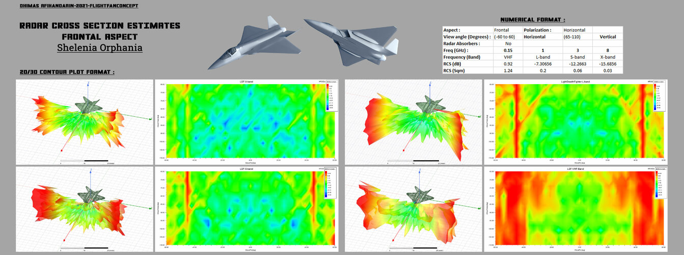
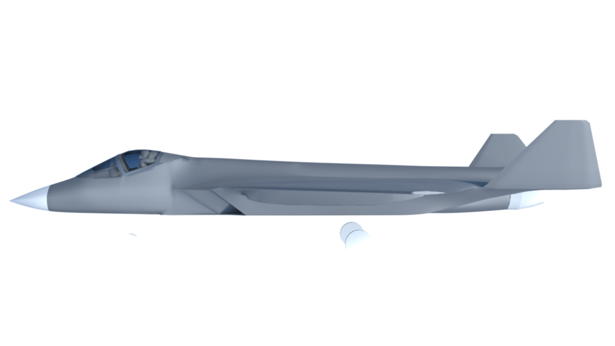
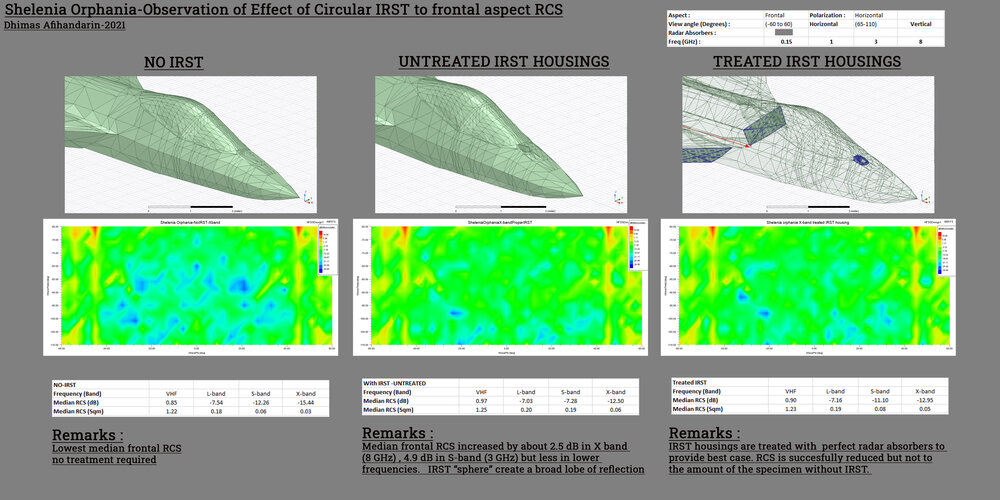
hmm i'm curious about the RCS reduction feature ? Like how smol your intended signature and in what frequency. I have kind of similar concept. basically my guesswork for LTS before unveiling. 0.01 sqm in X-band seems achievable from frontal aspect.

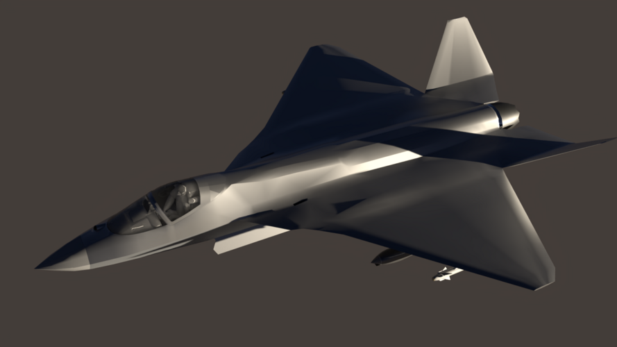
This is my concept.

Orphania.png

The estimates result.

RCSEstimates-SheleniaOrphania.jpg


The dimension tho, you might consider too big at 16.5m in length, and 12 m wingspan.
 

Attachments

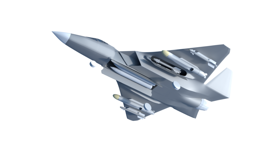
  • Firepower-1.png
    Firepower-1.png
    383 KB · Views: 297
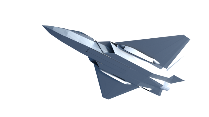
  • Lower Quarter.png
    Lower Quarter.png
    442.2 KB · Views: 285
  • Shelenia Orphania-2.png
    Shelenia Orphania-2.png
    186.8 KB · Views: 262
  • IRST Studies.jpg
    IRST Studies.jpg
    2.1 MB · Views: 289
hmm i'm curious about the RCS reduction feature ? Like how smol your intended signature and in what frequency. I have kind of similar concept. basically my guesswork for LTS before unveiling. 0.01 sqm in X-band seems achievable from frontal aspect.

This is my concept.

View attachment 670728

The estimates result.

View attachment 670730


The dimension tho, you might consider too big at 16.5m in length, and 12 m wingspan.

That's excellent work!

I can provide a solid 3D model as soon as I have it. What file format would you prefer? STL?
 
True, but the size of an internal weapons bay is not an independent variable, and existing implementations can give lower and upper bounds on what is practical.
That is fair enough but you can also choose to make other pwrformance trades that aren't in that small dataset. e.g. some air vehicle performance trades for lower range/endurance, acceleration, sustained turn rate probably allow for relatively larger bays. Or just use children as pilots o_O
 
If I understand you correctly the rule of thumb to estimate maximum take-off weight is multiplying total aircraft volume by 1000 (1000 kg/m³).

Here’s an interesting set of NASA conceptual studies that will give you some good weight and volume breakdowns… the density seems closer to 500 kg/m3.

Future Carrier-based Tactical Aircraft Study (1996)

See in particular the multirole fighter “90 MRF” (p.107) and “95 MRF” (p.171) designs. Some of the assumptions seem a little optimistic but the 95 MRF should be relevant with its internal bays and 9t empty weight.
 

Attachments

  • AA72240A-7716-4187-8D18-9077994941BF.jpeg
    AA72240A-7716-4187-8D18-9077994941BF.jpeg
    155.8 KB · Views: 290
  • Future Carrier based Tactical Aircraft Study 1996.pdf
    1.3 MB · Views: 95
what if rather one large bay for a light fighter

what about two smaller ones like on UCAVs?

what if rather one large bay for a light fighter

what about two smaller ones like on UCAVs?

PLZ0000AC07_2_d.jpg

Structurally, that looks much simpler and lighter than the - failed - Grumman A-12 Avenger II. The nose-wheel bay is far enough forward and the main-wheel bays plus bomb-bays are far enough aft that you can route a forward spar straight across to transfer loads between the wing leading edges. Straight load paths equal simpler and lighter structures.
 
If I understand you correctly the rule of thumb to estimate maximum take-off weight is multiplying total aircraft volume by 1000 (1000 kg/m³).

Here’s an interesting set of NASA conceptual studies that will give you some good weight and volume breakdowns… the density seems closer to 500 kg/m3.

Future Carrier-based Tactical Aircraft Study (1996)

See in particular the multirole fighter “90 MRF” (p.107) and “95 MRF” (p.171) designs. Some of the assumptions seem a little optimistic but the 95 MRF should be relevant with its internal bays and 9t empty weight.

Thanks @H_K , that's an interesting document for sure! I will read it as soon as I find some time...

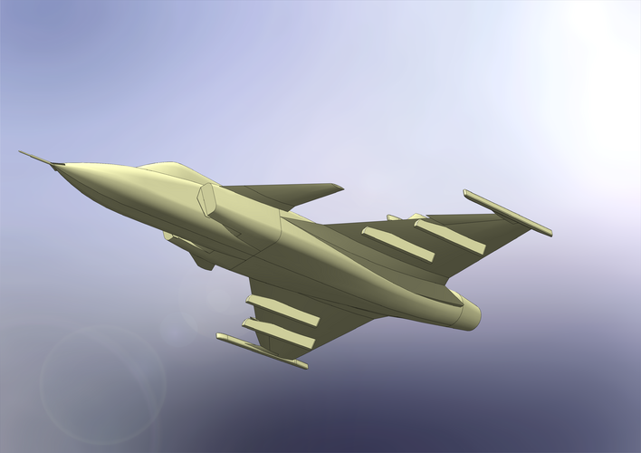
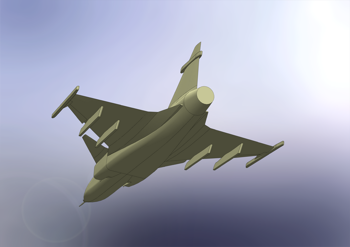
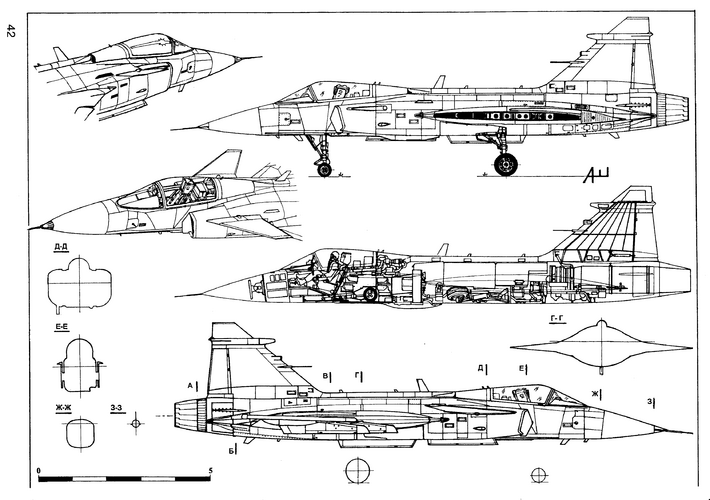
In the meantime I have created a CAD-model of the legacy Gripen. By doing that I can determine its volume an calculate the density. The CAD-model is not 100% accurate, but I'm confident it is more than enough for this purpose (see pics attached).

I can confirm the ~500 kg/m³ for maximum take off weight.

Here are the density numbers in reference to the CAD-model and the given specifications:
Total Aircraft Volume: 24,21 m³ (solid model, without any hollow space).
Empty Weight: 6622kg => 273,5 kg/m³
Max Weight: 14000kg => 578 kg/m³


Hence, I will aim for approximatley 27 m³ of aircraft volume => Gripen's total volume (24,21 m³) + desired weapons bay (2,72 m³) = 26,93 m³. By using the 273,5 kg/m³ I get an empty weight of approximatley 7400 kg.

In conclosion, this aircraft is expected to have the following specs:

1) An internal weapons bay (2,72 m³) that can accomodate four AIM-120C (650 kg), or a mix of other ordnace up to ~1000 kg.
2) A fuel tank volume equivalent to the legacy Gripen (2820 l / 2270 kg).
3) An empty weight of 7600 kg, which is equivalent to the Gripen NG.

In regards of take off weight:

1) Loaded with four AIM-120C and full internal fuel: ~10,5 t (10520 kg).
2) Loaded with the maximum internal load and full internal fuel: ~11 t (10870 kg).
3) "Beast Mode": Whatever it can lift without tumbling :)

That sounds like useful capability IMHO.
 

Attachments

  • Gripen_004.PNG
    Gripen_004.PNG
    3.3 MB · Views: 231
  • Gripen_005.PNG
    Gripen_005.PNG
    3.2 MB · Views: 169
  • Gripen_006.PNG
    Gripen_006.PNG
    3.2 MB · Views: 150
  • Gripen_007.PNG
    Gripen_007.PNG
    3.4 MB · Views: 154
VTOLicious, do you have other similar aircraft models with a known volume? There was too much difference with my methodology (24.2 m3 vs 33 m3). The volume of the Su-27 is known - 70 m2, the table turned out to be the same....
 
Last edited:
VTOLicious, do you have other similar aircraft models with a known volume? There was too much difference with my methodology. The volume of the Su-27 is known - 70 m2, the table turned out to be the same....

Unfortunately Gripen is the only one I have. Actually it was your 1000 kg/m³-claim that it inspired me to make it ;) I wanted to create evidence myself, so that I don't need to rely on the general assumptions found in textbooks.
 
In the paralay-table, the usual density of a modern fighter is 450 - 700 kg / m3, in the "first approximation" you can take 500 kg / m3 at maximum take-off weight.
 
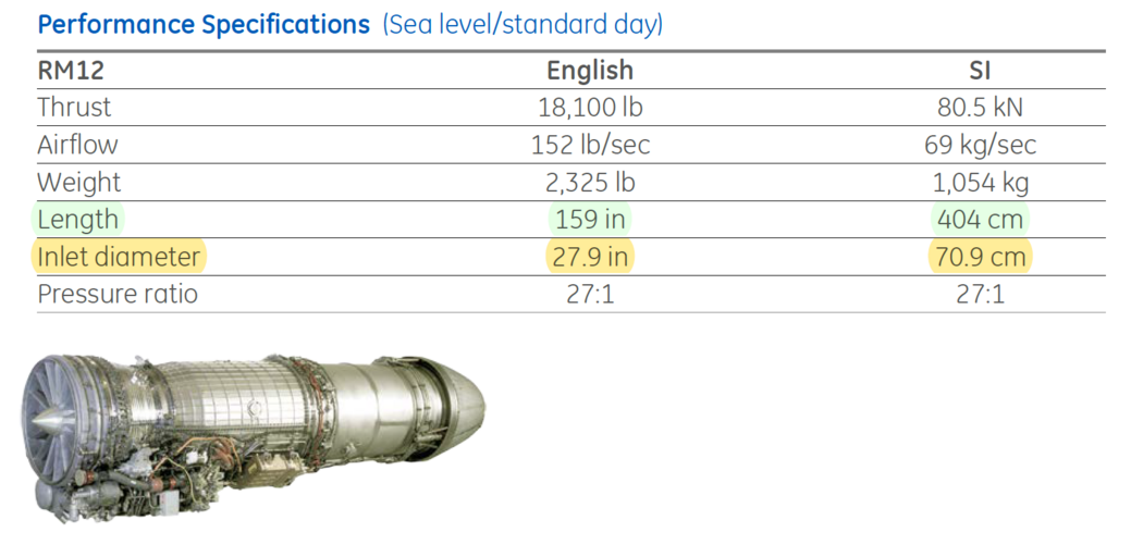
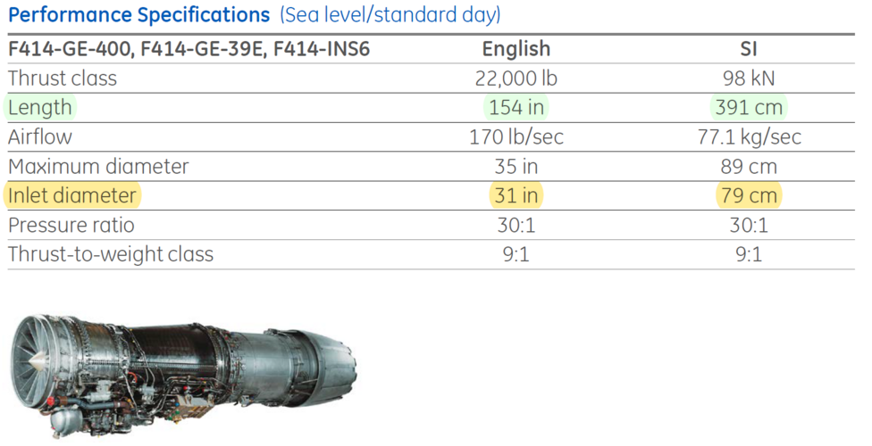
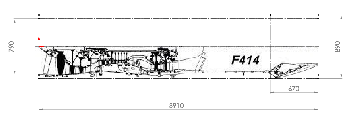
Can someone confirm that the specified intake diameter of the F414 engine is indeed 0,79m? I don't wanna waste valuable fuselage volume with oversized ducting.

And I would appreciate if someone could provide a decent drawing of the F414 or F404. I couldn't find anything useful on the internet.
In the drawings I currently have, the ratio of diameter to length does not match.
 

Attachments

  • GE_F414_004.PNG
    GE_F414_004.PNG
    306.1 KB · Views: 171
  • GE_F414_003.jpg
    GE_F414_003.jpg
    58.9 KB · Views: 176
  • GE_F404_001.jpg
    GE_F404_001.jpg
    66.6 KB · Views: 175
Last edited:

Thx for the pictures Paralay!

Here's the Problem:

Option 1:
Drawing scaled to overall length => Would give an inlet diameter of only 684 mm!
GE F404_RM-12_004.PNG

Option 2: Drawing scaled to inlet diameter => Would give an overall length of 4,5 m and a max diameter of 990 mm!
GE F404_RM-12_005.PNG

Option 3: Drawing scaled to engine length without the cone => Best match, but the true inlet diameter is now 700 mm!
GE F404_RM-12_006.PNG

I tend to agree with Option 3. But that would have an huge impact on intake area (and consequently on the volume consumed by the intake duct).

Diameter 0,79 m* => 0,490 m²
Diameter 0,70 m => 0,385 m²

*Perhaps the "inlet diameter" given in the specifications refers to the outside diameter of the inlet ring to which the duct would normally be attached.

It would be best if someone could measure it :)
 
Last edited:
*Perhaps the "inlet diameter" given in the specifications refers to the outside diameter of the inlet ring to which the duct would normally be attached.
I'd probably rely on the fan diameter number being most accurate. Difficult to know what the reference points are for the other dimensions e.g. far from clear where on the nozzle / which nozzle might be referenced
 
Can someone confirm that the specified intake diameter of the F414 engine is indeed 0,79m? ... And I would appreciate if someone could provide a decent drawing of the F414 or F404. I couldn't find anything useful on the internet. In the drawings I currently have, the ratio of diameter to length does not match.

Pretty much exactly the sort of problems I've run into when aspiring to sketch these things "realistically". Perhaps there'd be nothing lost in asking GE just how accurate dimensions they're willing to divulge, though haven't ventured as far myself. The F404, I presume, is a pretty well known quantity for friend and foe alike by now.
 
How about configuring it slightly asymmetrically?
My comment is inspired by Burt Rutan's ARES light-weight, ground-attack proof-of-concept.

Can you get by with a single engine inlet mounted on one side of the fuselage?

Internal airflow does not have to be perfectly symmetrical as long as it meets the compressor face at a reasonable angle.
Offsetting the intake trunk to one side would simplify fuselage internal design.

You could keep the bomb-bay almost on the center-line. It should be able to perform its primary mission with internal fuel and internal bombs and missiles. One large bomb-bay is easier to re-configure for weapons invented later.
If the internal 20 mm cannon is mounted on the opposite side, you do not need to worry about muzzle blast messing with engine intake air. I assumed an internal cannon because many Third World customers will struggle to afford missiles that cost hundreds of thousands of dollars each.

The main wheel on the intake side could retract aft into the space where the inlet trunk turns to meet the compressor face.
You may want to mount the nose-wheel slightly off-center to clear the bomb-bay.

Otherwise make it look like Aldo Spandoni minus the tail feathers. I would favor a diamond or delta wing planform.
Paddles - mounted on the engine tail-pipe - can substitute for tail feathers.
It would be fascinating to see a sketch of your design proposal riggerrob !!:oops:

Regards
Pioneer
 
As already indicated in my first post I’ll use the T-7A as a geometrical reference. Mainly because it is powered by a F404 engine and has a cross section that represents to a great extend what I have in mind – See the pic attached. Obviously it is designed as a trainer. Hence, it is smaller and lighter as the envisaged LMF and does not have basic stealth features like edge alignment.
The attached sketch shows the general arrangement of the 4 main items a little bit better. The drawing is not up to scale, but is not too far off I think.
Note: If a 14m long aircraft is assumed the combined length of engine and bay consume approximately 60% of overall length!
Loving the topic, your thought process and your drawings VTOLicious!!

If you don't mind me saying, I fully appreciate the want to squeeze as much fuel into a given area of your small LMF, but I can't help reflect on the inherent risk of fuel surrounding the engine at the rear of the fuselage, especially with the catastrophic combat experience with the likes of that found with the Republic F-105 in combat.....sorry, just a reflection.

Regards
Pioneer
 

Attachments

  • IMG_20220103_204645.jpg
    IMG_20220103_204645.jpg
    1,011 KB · Views: 252
Loving the topic, your thought process and your drawings VTOLicious!!

If you don't mind me saying, I fully appreciate the want to squeeze as much fuel into a given area of your small LMF, but I can't help reflect on the inherent risk of fuel surrounding the engine at the rear of the fuselage, especially with the catastrophic combat experience with the likes of that found with the Republic F-105 in combat.....sorry, just a reflection.

Regards
Pioneer
Adding my thoughts here too...

In a single engined fighter relying on FBW to keep it straight and narrow facing today's SAM's or AAM's any hit towards the rear of the plane will be disastrous as it will certainly impact on flight controls and almost certainly damage the engine meaning you are in a spot of trouble anyway! The Thud was designed as a fighter but flew as a bomber mostly dropping dumb bombs in well defended airspace. That airspace defense has improved exponentially in the fifty odd years since Vietnam. Even dumb bomb attacks these days is done with a computer calculated toss maneuver to minimize the aircraft's exposure to SAMs. Smart weapons from up high being the preferred choice these days.

Thus, do we really need to limit ourselves to lessons learnt in an era where our own weapons and that of the defender has improved to an degree where where the old lessons barely matter? The same argument goes for the gun/no gun argument. AAM's have come a very, very long way since Vietnam with a BVR shot being preferred now that we have networked IFF systems etc. almost standard in modern aircraft. Long gone are the days of the ROE for visual confirmation and poorly functioning missiles to boot... If you need a gun - pod it. Why waste very valuable internal space - especially when the goal is a very small stealth fighter. Sorry, I think I'm starting another debate now!

This is not an attack on you Pioneer, I'm sorry if it comes across as - not my intention. I just think the lessons of old need to be viewed within context especially if they unnecessarily constrain us in a different context where they no longer apply as strongly.
 
How about folding the fins on missiles that are stowed internally?
As far as I know a version of AIM-120 or equivalent missile with folding fins doesn't exist yet, unfortunate

Loving the topic, your thought process and your drawings VTOLicious!!

If you don't mind me saying, I fully appreciate the want to squeeze as much fuel into a given area of your small LMF, but I can't help reflect on the inherent risk of fuel surrounding the engine at the rear of the fuselage, especially with the catastrophic combat experience with the likes of that found with the Republic F-105 in combat.....sorry, just a reflection.

Regards
Pioneer
Adding my thoughts here too...

In a single engined fighter relying on FBW to keep it straight and narrow facing today's SAM's or AAM's any hit towards the rear of the plane will be disastrous as it will certainly impact on flight controls and almost certainly damage the engine meaning you are in a spot of trouble anyway! The Thud was designed as a fighter but flew as a bomber mostly dropping dumb bombs in well defended airspace. That airspace defense has improved exponentially in the fifty odd years since Vietnam. Even dumb bomb attacks these days is done with a computer calculated toss maneuver to minimize the aircraft's exposure to SAMs. Smart weapons from up high being the preferred choice these days.

Thus, do we really need to limit ourselves to lessons learnt in an era where our own weapons and that of the defender has improved to an degree where where the old lessons barely matter? The same argument goes for the gun/no gun argument. AAM's have come a very, very long way since Vietnam with a BVR shot being preferred now that we have networked IFF systems etc. almost standard in modern aircraft. Long gone are the days of the ROE for visual confirmation and poorly functioning missiles to boot... If you need a gun - pod it. Why waste very valuable internal space - especially when the goal is a very small stealth fighter. Sorry, I think I'm starting another debate now!

This is not an attack on you Pioneer, I'm sorry if it comes across as - not my intention. I just think the lessons of old need to be viewed within context especially if they unnecessarily constrain us in a different context where they no longer apply as strongly.
All good BLACK_MAMBA, I don't view your opinion/feedback as an attack mate.


Regards
Pioneer
 
As already indicated in my first post I’ll use the T-7A as a geometrical reference. Mainly because it is powered by a F404 engine and has a cross section that represents to a great extend what I have in mind – See the pic attached. Obviously it is designed as a trainer. Hence, it is smaller and lighter as the envisaged LMF and does not have basic stealth features like edge alignment.
The attached sketch shows the general arrangement of the 4 main items a little bit better. The drawing is not up to scale, but is not too far off I think.
Note: If a 14m long aircraft is assumed the combined length of engine and bay consume approximately 60% of overall length!
Loving the topic, your thought process and your drawings VTOLicious!!

If you don't mind me saying, I fully appreciate the want to squeeze as much fuel into a given area of your small LMF, but I can't help reflect on the inherent risk of fuel surrounding the engine at the rear of the fuselage, especially with the catastrophic combat experience with the likes of that found with the Republic F-105 in combat.....sorry, just a reflection.

Regards
Pioneer
Would a dorsal inlet be simpler/lighter/easier to implement here?
Yes, I too have had that notion, but alas AOA issues perhaps...

When I first reading this topic/post, the first design that came to mind was the Bill Gunston design from his books Stealth Warplanes. Osprey Combat Aircraft Series.Bill Gunston. 1988
Granted it's V/STOL attack fighter, but it has many characteristics - internal weapons bay, dorsal intake, low RCS, ......
Perhaps get rid of the V/STOL aspect of this fictitious design could derive something.....


Regards
Pioneer
 

Attachments

  • IMG_20220103_213538.jpg
    IMG_20220103_213538.jpg
    968.5 KB · Views: 298
Would a dorsal inlet be simpler/lighter/easier to implement here?

That got me thinking... how about something like a stealthy version of Northrop's N333/N336 design from 1978? Lightweight (7.5t empty... perhaps a little optimistic), lots of internal volume (5.7t internal fuel), plus space for a conformal ventral pod... make it powered by a single F414 EPE (26,000lb thrust), maybe shrink it a little and it should be good.


@VTOLicious LOTS of detail available that would allow you to model this in CAD. Density of the N336 design appears to be 597 kg/m3... (not sure if there's a typo because the image says 59.7kg/m3).

vatol-inboard-jpg.159518

vatol-ga-jpg.159516

northrop-vatol-2-jpg.48613
 
Last edited:
Would a dorsal inlet be simpler/lighter/easier to implement here?

That got me thinking... how about something like a stealthy version of Northrop's N333/N336 design from 1978? Lightweight (7.5t empty... perhaps a little optimistic), lots of internal volume (5.7t internal fuel), plus space for a conformal ventral pod... make it powered by a single F414 EPE (26,000lb thrust), maybe shrink it a little and it should be good.


@VTOLicious LOTS of detail available that would allow you to model this in CAD. Density of the N336 design appears to be 597 kg/m3... (not sure if there's a typo because the image says 59.7kg/m3).

vatol-inboard-jpg.159518

vatol-ga-jpg.159516

northrop-vatol-2-jpg.48613

That's indeed a nice concept! ...and drawing!

Without a doubt a dorsal inlet frees up lots of internal volume. However, the question remains if it's applicable for a fighter aircraft.

I ruled out a dorsal inlet from the onset, as there isn't a single practical example of a modern fighter / stealth fighter that features that type of inlet.
 
Without a doubt a dorsal inlet frees up lots of internal volume. However, the question remains if it's applicable for a fighter aircraft.

I ruled out a dorsal inlet from the onset, as there isn't a single practical example of a modern fighter / stealth fighter that features that type of inlet.
Saab were very close in the Gripen project but they also judged it as too high risk. A dorsal intake will solve a lot of the geometry and volume problems for stealth fighter design, yet nobody wants to move past the design stage! There are enough examples spread over this forum. At the same time plenty of sources say it can be done if designed correctly? Two seemingly contradicting stand points - too risky and not worth it and yes it can be done. Hopefully it gets tried in a proper high alpha X-project somewhere someday and a more definitive answer given. And no, the F-107 doesn't answer it.;)
 
We should remember that the Handley Page 115 with its well aft dorsal intake flew around at 35deg AoA without issue. Those sharply swept wings forming strong vortices each side of the intake allowing for cleaner flow down the centreline.
 
the draken was mentioned here as something from the past whose form factor could be viable for an LMF

what about the Delta Dart?.
it had an internal bay. its long but relatively light.
640px-F-106A_119th_FIS_weapons_bay_with_AIM-4_1984.JPEG
 
There are a number of aircraft designs that have flown successfully with dorsal inlets, a list provided below. However, the high-alpha maneuvering requirement at supersonic speeds makes designing such an aircraft challenging. If high AOA maneuverability in the supersonic realm is a design point for this design then a dorsal inlet could be a significant compromise not worth pursuing. To validate such a design a significant amount of testing (wind tunnel, CFD, free-flight models, etc.) to justify its implementation would be needed. For a design exercise of this nature the limiting factor is what resources you have available.

Dorsal mounted inlet aircraft that have flown (or planned to fly), with varying degrees of success (manned and unmanned):

Boeing Bird of Prey
Lockheed F-117A
Boeing B-2
Northrop Tacit Blue
Boeing MQ-25 - Unmanned
Handley Page 115
North American F-107
SE 2410 Grognard
Avro 707
Soon to fly Boeing B-21
Soon to fly Boom Supersonic Aircraft XB-1
Soon to fly Lockheed X-59
 
I don't think any questions exist about if a dorsal inlet works. As listed, there are plenty examples that it does. However, the issue currently being discussed here is a dorsal inlet in a high AoA environment - ie in dogfighting! Although there are plenty examples on this forum of such designs existing... Hence why I think an X-aircraft aimed at investigating that regime is required.
Maybe that should be an indicator that for the design being conceived here it isn't worth the risk/effort as Dynoman suggested?
 
Should this proposed LWF have thrust vectoring (dog-fighting) or thrust reverse (short landing)?
 
Supersonic manouvering is low AoA because otherwise you're pulling ridiculous gs

Low speed high AoA + high Beta i.e. crosswind landing or high AoA roll in dogfighting are probably the dominating cases. These seem within the flying examples already unless post stall manoeuvring is also desired. Still, in this flight regime there's nothing to stop various suck in doors being added.

But its still more risk so the benefit on configuration packaging and performance should be quantified
 
This is not entirely true. IMOHO, future fight will see high altitude fighters dogfighting at supersonic speed (at least for the first set of turns). There, High Aoa at supersonic speed will make all the difference.
 
This is not entirely true. IMOHO, future fight will see high altitude fighters dogfighting at supersonic speed (at least for the first set of turns). There, High Aoa at supersonic speed will make all the difference.

50 Deg AoA at Mach 1.5 =

Squishy brained pilot
Airframe basically a solid lump
Slowing down really fast

"High" AoA at supersonic speeds is more like 5-10deg. Take-Off/Landing will be worse - unless it's VTOL
 
High alt means that 25deg will be reached at the onset of any hard maneuvring. Hence high AoA...
 
High alt means that 25deg will be reached at the onset of any hard maneuvring. Hence high AoA...

Do that maths and you'll find that this isn't the case. You'll definitely be g limited rather than lift limited.

Lift coefficient = g * Lift / (0.5 * density * Velocity^2 * wing area)

Typical supersonic lift coefficient ~2 per rad
 
How can you be g limited when you manoeuvre out of plan? The first thing you'd want to do is convert excess speed for extra alt where you'll get a higher alpha rate to change trajectory.
See the merge at 65kft with a pull up up to 90kft where you'll convert your rate of climb into alpha rate and drop down on your adversary...

AoA will rule there like everywhere else.
 

Similar threads

Please donate to support the forum.

Back
Top Bottom