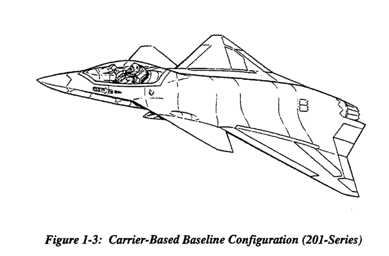
How about starting with the F-16XL as a base, adding DSI, switching to a F414, adding two fins, and going with semi-recessed missiles. More of a reduced RCS from front than all angle RCS.

As for dorsal intakes you can always do something like the A-4.
 
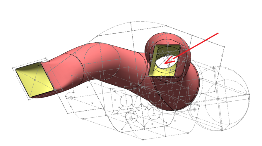
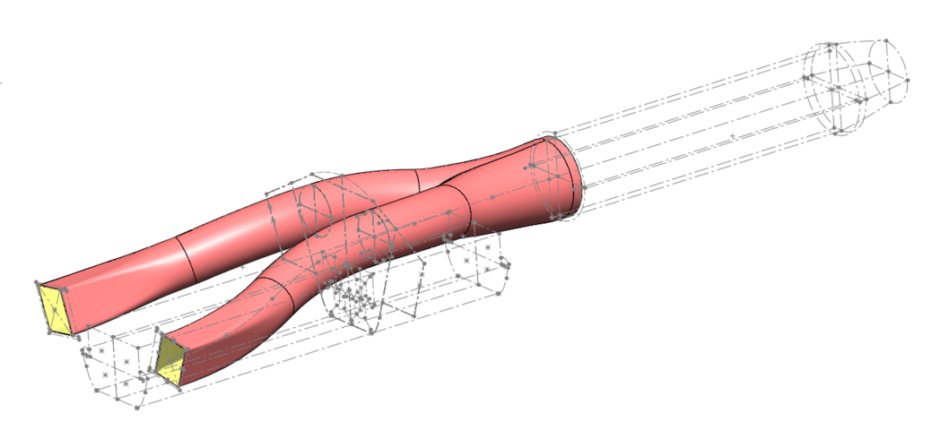
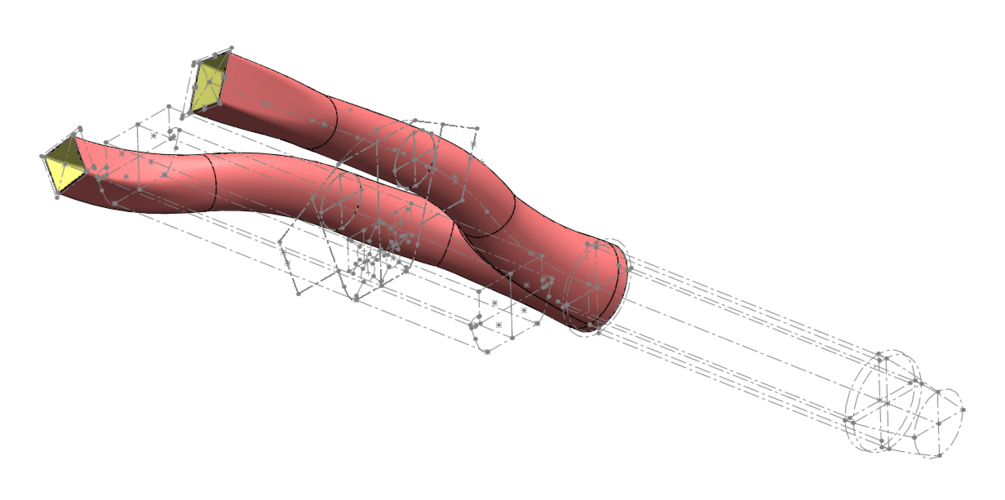
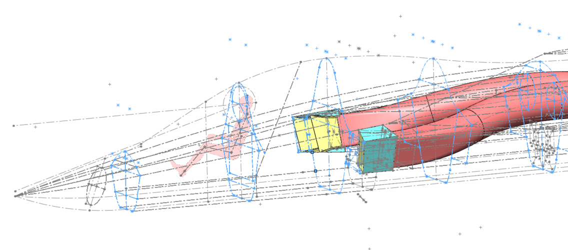
After several iterations and some tweaking of the airframe cross section and duct geometry I have a first draft of the basic layout in 3D. It was quite a challenge to force the duct into the right shape :)

The duct consists of four sections, its center line measures 5,33 m, and the cross section widens towards the engine by a constant factor (~1,5).
The duct hides the engine face when viewed from the front, but it is visible from certain angles. Especially if you look at the intake from below / sideways. Maybe a fan blocker à la Super Hornet should be considered?

Btw, the airframe cross section as depicted measures 2,6 m². It may change a little in the design process, but I aim to keep it in that realm.

LMF_S-Duct_004.PNG
 

Attachments

  • LMF_S-Duct_001.PNG
    LMF_S-Duct_001.PNG
    139.9 KB · Views: 208
  • LMF_S-Duct_002.PNG
    LMF_S-Duct_002.PNG
    144.2 KB · Views: 166
  • LMF_S-Duct_003.PNG
    LMF_S-Duct_003.PNG
    202.4 KB · Views: 332
Last edited:
That is looking very good VTOlicious. A blocker might be considered but I also think that angle wil only be held for a second or two at best against any radar - not enough to track or fire. Northrop's F-23 evolution also allowed one to see the fan face from the front and certain angles - and they know what they are doing! I haven't heard/read about an intended fan blocker for the F-23 but it isn't impossible.
Any radio waves were thus likely to bounce around in the intake geometry likely delaying or dissipating them away from source. I think the same will apply to this design?
 
I really want to see a VTOL SU-75 render, the rear end already looks great for a tilting nozzle!
 
  • side view 21.58 m2
  • top view 55.54 m2
  • front view 4.46 m2
  • volume 35 m3
  • max. take-off weight 17500 kg
  • wing area 38 m2
  • weapons bay 2.58 m3 / 7.4%

That's a neat looking airplane!

Is it intended for STOL or VTOL operations?
Wouldn't it be nose heavy, with the core engine installed that far to the front?
 
Last edited:
This is a vertical take-off and landing fighter corresponding to the sixth generation in terms of thrust-to-weight ratio. Based on the engine "izd.30". Thrust-to-weight ratio at maximum take-off weight is equal to one. With a normal take-off weight, the fighter will take off vertically at any ambient temperature.
I did not count on centering for this project, I hope the heavy nose is balanced by an equally heavy tail section
 
After several iterations and some tweaking of the airframe cross section and duct geometry I have a first draft of the basic layout in 3D. It was quite a challenge to force the duct into the right shape :)
What is "the right shape"? (Besides circular at the fan face)

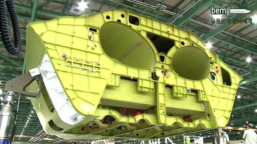
There are quite a few pictures on here of different duct geometries that are much more non circular in their central regions than what you've drafted. e.g.

https://news.northropgrumman.com/news/releases/photo-release-northrop-grumman-takes-delivery-of-first-production-f-35-air-inlet-duct-from-key-turkish-supplier

To work out your max cross sectional area its useful to draft some cross sections at different longitudinal positions e.g. probably a big bulkhead at the rear of the payload bay - and then have a think about the minimum clearances and structural depths that are probably required. Where do the load paths go?
 
After several iterations and some tweaking of the airframe cross section and duct geometry I have a first draft of the basic layout in 3D. It was quite a challenge to force the duct into the right shape :)
What is "the right shape"? (Besides circular at the fan face)
The right shape is the one that fits ;)
Without a doubt, in the real world a whole engineering team would work on the air ducting. My intention is to create a 3D-model that is representative on a conceptual level. Hence, the main task is to route a duct with a realistic volume trough the fuselage and have a look how much volume is left for fuel.

There are quite a few pictures on here of different duct geometries that are much more non circular in their central regions than what you've drafted. e.g.
Yes, I'm aware of that, e.g. KF-21... However, there is nothing wrong with a circular duct cross section.

El96ym6UcAASHPG.jpg


To work out your max cross sectional area its useful to draft some cross sections at different longitudinal positions e.g. probably a big bulkhead at the rear of the payload bay - and then have a think about the minimum clearances and structural depths that are probably required.
That`s what I'm currently doing!

LMF_S-Duct_005.PNG

By the way, do you have a suggestion what would be representativ for the maximum thickness of the wing, at the root and at the tip? For the Saab Gripen I've used 210mm / 110mm (as suggested by the 3-view drawing).

Gripen_008.PNG
 
What is "the right shape"? (Besides circular at the fan face)

There are quite a few pictures on here of different duct geometries that are much more non circular in their central regions than what you've drafted. e.g.

...

To work out your max cross sectional area its useful to draft some cross sections at different longitudinal positions e.g. probably a big bulkhead at the rear of the payload bay - and then have a think about the minimum clearances and structural depths that are probably required. Where do the load paths go?

My (fairly general) impressions are that loads are quite amenable to following circular paths. The F-35's ducting is interesting. Twisty, ~45 degree angles, quite a lot of surface area per volume to potentially produce downstream boundary layer effects. On the other hand, the ducts seem somewhat short, perhaps compensating for whatever compromises might otherwise have been made in optimizing that shape for its purposes.

That`s what I'm currently doing!

Am I wrong in thinking that resembles MAKO a lot? Guessing you'll lose the second seat at some point.

By the way, do you have a suggestion what would be representativ for the maximum thickness of the wing, at the root and at the tip? For the Saab Gripen I've used 210mm / 110mm (as suggested by the 3-view drawing).

Perhaps someone can point you to resources depending on the geometries you prefer/would like to try. Wing loading, aspect ratio surely will have something to do with those specific dimensions.
 
By the way, do you have a suggestion what would be representativ for the maximum thickness of the wing, at the root and at the tip? For the Saab Gripen I've used 210mm / 110mm (as suggested by the 3-view drawing).

Aiming for an airfoil thickness to chord ratio of 3 to 6% (according to aspect ratio, low -> lower t/c) should get you reasonable values.

EDIT: Just to add, the t/c ratio need not be the same at root and tip, and in fact the tip may, somewhat counter-intuitively, have a *higher* t/c on wing planforms with a low taper ratio (e.g. high sweep delta). The Gripen may well be such a case, incidentally.
 
Last edited:
By the way, do you have a suggestion what would be representativ for the maximum thickness of the wing, at the root and at the tip? For the Saab Gripen I've used 210mm / 110mm (as suggested by the 3-view drawing).

Aiming for an airfoil thickness to chord ratio of 3 to 6% (according to aspect ratio, low -> lower t/c) should get you reasonable values.

EDIT: Just to add, the t/c ratio need not be the same at root and tip, and in fact the tip may, somewhat counter-intuitively, have a *higher* t/c on wing planforms with a low taper ratio (e.g. high sweep delta). The Gripen may well be such a case, incidentally.
Thx for your input!
 
What is "the right shape"? (Besides circular at the fan face)

There are quite a few pictures on here of different duct geometries that are much more non circular in their central regions than what you've drafted. e.g.

...

To work out your max cross sectional area its useful to draft some cross sections at different longitudinal positions e.g. probably a big bulkhead at the rear of the payload bay - and then have a think about the minimum clearances and structural depths that are probably required. Where do the load paths go?

My (fairly general) impressions are that loads are quite amenable to following circular paths. The F-35's ducting is interesting. Twisty, ~45 degree angles, quite a lot of surface area per volume to potentially produce downstream boundary layer effects. On the other hand, the ducts seem somewhat short, perhaps compensating for whatever compromises might otherwise have been made in optimizing that shape for its purposes.

That`s what I'm currently doing!

Am I wrong in thinking that resembles MAKO a lot? Guessing you'll lose the second seat at some point.

By the way, do you have a suggestion what would be representativ for the maximum thickness of the wing, at the root and at the tip? For the Saab Gripen I've used 210mm / 110mm (as suggested by the 3-view drawing).

Perhaps someone can point you to resources depending on the geometries you prefer/would like to try. Wing loading, aspect ratio surely will have something to do with those specific dimensions.

Yes, MAKO is used as a reference:
https://www.secretprojects.co.uk/th...ultirole-fighter-lmf.38539/page-2#post-507003

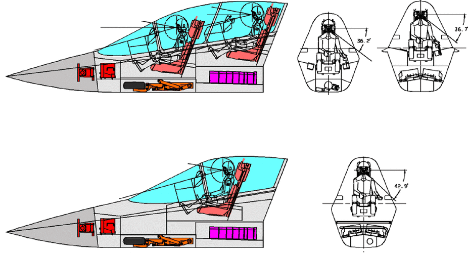
I found a pretty good drawing of MAKO's nose section. As you can see it features a one- and two-seater.
I decided to use the layout of the two-seater, but use the additional space for fuel, to (partially) compensate the fuselage volume lost due to the internal weapons bay. An avionics compartment right behind the pilot will be included as well. Furthermore, I think the "hump layout" is beneficial for area ruling.

mako_04_p.gif
 
I like the way this thread is getting into detailed design of intakes and cockpits.
I agree with VTOLicious that a 2-seater version is superfluous. Consider the examples of F-22 and F-35 that lack 2-seater variants and depend instead on ground-based simulators for pilot proficiency. Any Third-World air force is going to struggle to pay for flight time and will cheerfully rent simulator time to keep their pilots current.
 
Next steps…
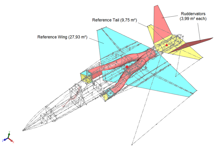
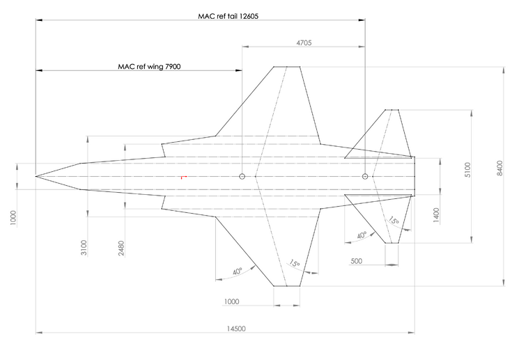
To be able to determine the location of the main landing gear and proceed with the fuselage design I have to decide on a wing and tail layout. Here is what I have so far:

Reference Wing:
Span: 8,4 m (Gripen L)
Reference Area: 27,93 m² (approx. F-16)
Aspect Ratio: 2,53
LE Sweep: 40° (F-16)
TE Angle: 15°

Reference Tail:
Span: 5,1 m
Reference Area: 9,75 m²
Aspect Ratio: 2,67

Ruddervators (V-Tail):
Dihedral Angle: 45°
True Area: 3,99 m² (each) => approx. 29% of wing reference area
Projected Area: 2,82 m² (each) => approx. 20% of wing reference area

Fuselage Length: 14,5 m
Location of MAC-Wing relative to the Nose: 7,9 m (54,5% of fuselage length)
Distance MAC-Wing to MAC-Tail: 4,705 m

And for the sake of completeness:

Empty Weight: 7600 kg (Gripen NG)
Max. Weight: 16500 kg (Gripen NG)
Wing Loading (Empty): 272 kg/m²
Wing Loading (Max.): 591 kg/m²
Internal Fuel: 2821 l (2268kg @ 0,8kg/l) (Gripen L)
Engine: GE F414 (Gripen NG)
Thrust without AB: 63,47 kN
Thrust with AB: 97,99 kN

All of that is preliminary parameters. Comments welcome!

LMF_Specs_014.png
 
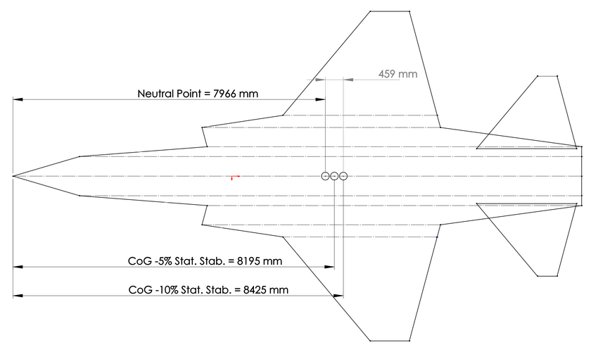
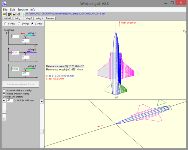
To get an rough idea where the center of gravity is located relative to the neutral point I have used a simple software tool called WinLaengs4 (intended for RC-airplanes).

I think the tool is accurate enough for a first estimation. The only concern: The tool doesn't have an option for dihedral angles. Therefore, I've set the projected area of the ruddervators to an elevated level above the wing (half of the height). I think that should be good enough for static stabilty calculation.

In the attached drawing the CoG position for a negative static stabiliy of -5% and -10% is shown. Any ideas what is a common number for combat aircraft which are designed longituinally unstable? (e.g. F-16).

LMF_Specs_017.PNG

LMF_Specs_016.PNG
 
I may be missing something but the wings seem somewhat small; given that you're using F-16's LE sweep but Gripen's span how isn't the effective wing area smaller than F-16's (the span of which is ~1.5m greater than Gripen's)?

Also, regarding the ruddervator dihedral, is 45° just a notional value or somehow considered? Combined they make for 90° which is pretty much a radar reflector from certain viewpoints. Considering stealth, not only edge alignment but surface alignment also seems to be important. In MAKO's transverse section its lower sides' angle (where flat) seem to consistently be about 20°. If at all feasible perhaps the ruddervators could follow that geometry (or rather, those geometries should, where possible, align)?

Thinking about geometry, stealth and aerodynamics, with the F414 most of the "flying" with this fighter will surely be subsonic but still, some consideration given to how this geometry conforms to the area rule as well might be nice.
 
If you're getting into this level of detail I'd really recommend looking at the thread on Aircraft Design Textbooks / software. The likes of Rayner, Roskam, Anderson etc have far more both data and methods extracted from the datasets.

e.g. how to do preliminary sizing of tails/fins for different classes of aircraft

There's also the process to go through e.g. "how big should the wing be?" What factors influence this
 
I may be missing something but the wings seem somewhat small; given that you're using F-16's LE sweep but Gripen's span how isn't the effective wing area smaller than F-16's (the span of which is ~1.5m greater than Gripen's)?

Also, regarding the ruddervator dihedral, is 45° just a notional value or somehow considered? Combined they make for 90° which is pretty much a radar reflector from certain viewpoints. Considering stealth, not only edge alignment but surface alignment also seems to be important. In MAKO's transverse section its lower sides' angle (where flat) seem to consistently be about 20°. If at all feasible perhaps the ruddervators could follow that geometry (or rather, those geometries should, where possible, align)?

Thinking about geometry, stealth and aerodynamics, with the F414 most of the "flying" with this fighter will surely be subsonic but still, some consideration given to how this geometry conforms to the area rule as well might be nice.
You can easily check the wing area if you want. It is what it is.

If the dihedral angle would be aligned with the side walls (of the intakes) the ruddervators wouldn't have enough projected area for sufficient pitch stability/ control... 45° isn't a necessity, could be 48,65321° as well ;)

Yes, I consider area ruling in the design process. Once I have three-dimensional model available we will see how it performs in that regard.
 
Last edited:
If you're getting into this level of detail I'd really recommend looking at the thread on Aircraft Design Textbooks / software. The likes of Rayner, Roskam, Anderson etc have far more both data and methods extracted from the datasets.

e.g. how to do preliminary sizing of tails/fins for different classes of aircraft

There's also the process to go through e.g. "how big should the wing be?" What factors influence this

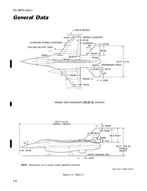
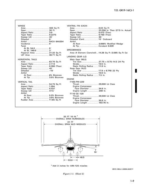
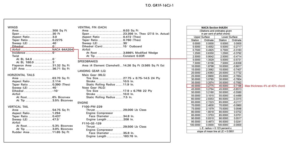
Yes, you are absolutely right. However, to get an idea of reasonable sizing of wings, control surfaces and the like I had a look if and what data of similar sized fighter aircraft is available and finally found some useful (first hand) information on the F-16 (C), which is a good reference I think...

ElrWSnuXEAQ4Hfl.jpg ElrWSnyXgAIewbQ.jpg
 
Main wheels are normally 15 to 17 degrees aft of the center-of-gravity.
C. of G. is normally at 25 percent of mean aerodynamic chord on conventionally stable airplanes ... farther aft with electronic stability augmentation.
Nose wheel as far forward as you can mount it without interfering with engine intakes or radar. Nose wheel can be a bit off-center if it simplifies internal lay-out.
 
By the way, do you have a suggestion what would be representativ for the maximum thickness of the wing, at the root and at the tip? For the Saab Gripen I've used 210mm / 110mm (as suggested by the 3-view drawing).

Aiming for an airfoil thickness to chord ratio of 3 to 6% (according to aspect ratio, low -> lower t/c) should get you reasonable values.

EDIT: Just to add, the t/c ratio need not be the same at root and tip, and in fact the tip may, somewhat counter-intuitively, have a *higher* t/c on wing planforms with a low taper ratio (e.g. high sweep delta). The Gripen may well be such a case, incidentally.

Found some info on the F-16...
ElrWSnyXgAIewbQ_a.jpg

*For simplicity of the 3D-model I'm gonna use a biconvex airfoil with the maximum thickness at 50% of chord length. Should be sufficiently accurate to determine wing's the volume ( available for fuel ).
 
Last edited:
what are the advantages and disadvantages of a vertical tail canted inwards rather than outwards

like on some other light stealthy designs like the Have Blue?
RFjLe09sOHJyNb7mKJO50kEktrbLZUOM06vOB6YVZTA.jpg
 
By the way, do you have a suggestion what would be representativ for the maximum thickness of the wing, at the root and at the tip? For the Saab Gripen I've used 210mm / 110mm (as suggested by the 3-view drawing).

In terms ow wing design, There are quite a few factors you may wish to consider depending on the amont of detail you wish to include.
I expect this might be basics for you but you never know on the internet...

For thickness:
The lift distribution at MTOW and G forces (usually elliptical, but can be bell shaped too) helps to define the maximum bending moment at the root. From that and the strength of the material you use you can design your attachment width (spacing between the pins)

For planform:
If you want a high turnrate/high lift at high AOA, you might consider the principles behind the delta wing (ie: 50+ deg sweep) or some special upper surface vortex generators such as the LERX on the F-18/16 etc or cannards

On a simple level, the rest of the wing performace i guess lies in the control surfaces and FCS/aerodynamic instability (with CG very close or even aft of CL).
Other than that you'd be going into complex CFD i think...

Hopefully this helps
 
this came out on Dark Skies recently
and I still think the X-36 by Boeing would be an ideal light (or perhaps midweight fighter).
The flight tests confirmed its good agility, AoA, reduced RCS and range
things you'd want out of the performance in a light weight aircraft that you expect to fly closer to the front lines
its claimed to be superior to performance than the Hornet as well.

since its a 28% scale model, I assume a full production sized one may be closer in size to the original Hornet

View: https://www.youtube.com/watch?v=ugoApJXpoUQ

Despite flight testing of the X-36 predates first flight of the X-32 by 3 years Boeing didn't consider a tailless design for JSF. Most probably there where unsolved issues, despite the general success of the X-36 program. Yaw control during engine operation at low thrust levels (e.g. landing approach) could be one of them.
at that time Boeing and McDonnell Douglas were separate companies, so naturally Boeing had their own design for JSF.
After Boeing acquired McD, they adopted a number of the X-36's features into their X-45
as the video stated, a reason why it didnt go any further into a full scale model was the expense involved
and likely the lack of demand since Boeing by then already was invested in the X-32
 
Next steps…
To be able to determine the location of the main landing gear and proceed with the fuselage design I have to decide on a wing and tail layout. Here is what I have so far:

Reference Wing:
Span: 8,4 m (Gripen L)
Reference Area: 27,93 m² (approx. F-16)
Aspect Ratio: 2,53
LE Sweep: 40° (F-16)
TE Angle: 15°

Reference Tail:
Span: 5,1 m
Reference Area: 9,75 m²
Aspect Ratio: 2,67

Ruddervators (V-Tail):
Dihedral Angle: 45°
True Area: 3,99 m² (each) => approx. 29% of wing reference area
Projected Area: 2,82 m² (each) => approx. 20% of wing reference area

Fuselage Length: 14,5 m
Location of MAC-Wing relative to the Nose: 7,9 m (54,5% of fuselage length)
Distance MAC-Wing to MAC-Tail: 4,705 m

And for the sake of completeness:

Empty Weight: 7600 kg (Gripen NG)
Max. Weight: 16500 kg (Gripen NG)
Wing Loading (Empty): 272 kg/m²
Wing Loading (Max.): 591 kg/m²
Internal Fuel: 2821 l (2268kg @ 0,8kg/l) (Gripen L)
Engine: GE F414 (Gripen NG)
Thrust without AB: 63,47 kN
Thrust with AB: 97,99 kN

All of that is preliminary parameters. Comments welcome!

View attachment 671290

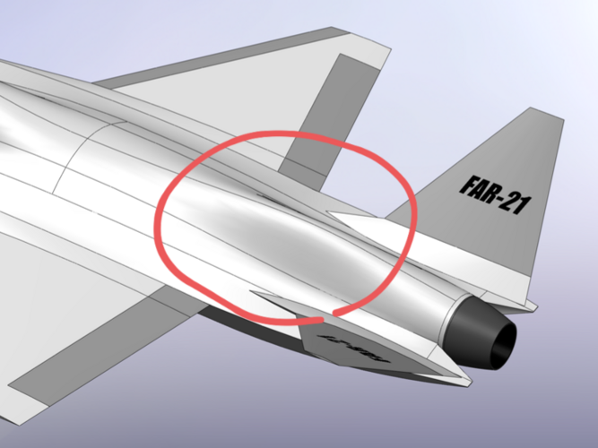
Here we go, the FAR-21 Griffin is born. One can guess what FAR stands for ;)
 

Attachments

  • LMF_X_101.PNG
    LMF_X_101.PNG
    668.1 KB · Views: 329
  • LMF_X_101-1.PNG
    LMF_X_101-1.PNG
    861.1 KB · Views: 295
  • LMF_X_102.PNG
    LMF_X_102.PNG
    659.2 KB · Views: 278
  • LMF_X_102-1.PNG
    LMF_X_102-1.PNG
    889.2 KB · Views: 281
Superb work. A true son of the mighty F-20 Tigershark.

If you want it to more closely follow the area rule, you'll certainly have to replace the aft positioned ruddervator with a vertical (think M2K) or fill the gap b/w the wing trailing edge with a section increase of some sort.
 
Last edited:
very nice work VTOLicious

it reminds me a bit of the McDonnel Douglas JAST
cddr_mda-ngc-bae_003.jpg


question on your canopy though. is a bubble canopy with nearly 360 view coverage no longer needed in new combat aircraft?
it seems that most of the 5th gen have primarily forward looking canopies (FC-31, F-35, KF-21, etc). the only ones with a bubble are the F-22 and J-20
 
Are you planning on a separate airbrake? With a v-tail (interleaving pitch and yaw control) you probably need split inboard/outboard wing TE control surfaces that can deflect differentially if not.
 
Superb work. A true son of the mighty F-20 Tigershark.

If you want it to more closely follow the area rule, you'll certainly have to replace the aft positioned ruddervator with a vertical (think M2K) or fill the gap b/w the wing trailing edge with a section increase of some sort.
Thank you. I like the F-20 analogy.

In regards of area rule: Have a close look. It actually has a "hump" to fill the gap between wing an V-tail.
20220118_100848.png
 
very nice work VTOLicious

it reminds me a bit of the McDonnel Douglas JAST
cddr_mda-ngc-bae_003.jpg


question on your canopy though. is a bubble canopy with nearly 360 view coverage no longer needed in new combat aircraft?
it seems that most of the 5th gen have primarily forward looking canopies (FC-31, F-35, KF-21, etc). the only ones with a bubble are the F-22 and J-20
McDD JAST may appear similar on the first look, but it is totally different. Trapezoid wing vs lambda wing, butterfly tail vs V-tail, variable IWB vs conventional IWB, etc... and it's a heavier/ larger aircraft anyways.

Canopy: I made the same observations. I think DAS in combination with HMD does provide adequate 360° view coverage nowadays (and more).
 
Are you planning on a separate airbrake? With a v-tail (interleaving pitch and yaw control) you probably need split inboard/outboard wing TE control surfaces that can deflect differentially if not.
To save weight I would like to keep the number of control surfaces (and associated actuators) to the necessary minimum. The suggested inboard/outboard* flaperons may be the better option.

*edited
 
Last edited:
Speaking of McDD JAST... I deliberately chose to start with a rather conservative layout. From here we can discuss design options. E.g. advantages and disadvantages of a lambda wing.
 

Similar threads

Please donate to support the forum.

Back
Top Bottom