- Joined
- 18 March 2008
- Messages
- 3,529
- Reaction score
- 978
CliffyB said:That link doesn't work JCF.
Its a strange one. The link is dead because the mods have merged the two threads as suggested. So you are actually where the link wants you to go!
CliffyB said:That link doesn't work JCF.
I believe it was 1,250 feet long with an entrance width of 150 feet, not sure about sill depth. Presumably a lot of the dredged material would be used as infill.JFC Fuller said:Quick of the mark PMN1, thanks!.
That is a monstrous dock, given that C and D docks are 850ft long that dock must be 1000-1250 ft long and thus much larger than required for CVA01.
There must have been some serious dredging planned.
zen said:Are they designing this for the USN?
zen said:Are they designing this for the USN?
Hobbes said:zen said:Are they designing this for the USN?
No, they were designing this 50 years ago for the (cancelled) CVA01 project.
When one thinks on the issues of fitting aboard aircraft to OR346 and equivalent US designs it would certainly have seemed prudent to say design a drydock to take the larges USN CVN and then add a bit more Length just to be safe.Hood said:The ability to dock a USN carrier would have been an obvious bonus.
I suspect this was some degree of future proofing given the lack of docks had hampered the 1950s carrier projects, some of which were 1,000ft long.
PMN1 said:Nimitz class CVN's look to be around 12ft wider overall than the QE class so should be doable, though some dredging would probably have been needed as it has been for the QE class.
zen said:Thank you for sharing that, I've missed such reading material, and thank you for sharing the information.
Quite a plan!
The amount of dredging they must have been planning is not trivial and would need refreshing every so often.
But like the later Portsmouth plan, this moves the complete CV support away from the likes of Rosyth and ... that bridge.

Does Cdr. Hobbs give the dimensions & displacement of the "Iwo Jima style commando ship"?The just issued book on British Carriers by David Hobbs (see thread in the books section for ref) adds some tantalising information to existing sources and confirms somethings we already know.
Hobbs explains in fairly brutal terms that the 1963 Escort Cruiser design was a non starter once work began on desigining and building Polaris submarines. Interestingly he refers to the final design having one Seadart launcher only, which makes more sense that the earlier idea of two Seadarts and an Ikara.
The 4 Escort Cruisers (to replace the Tiger conversions in the 70s) and 2 replacement Commando Ships (to replace Bulwark and Albion in the 70s) remained in the long term costings but no work was done on them.
Fast forward to the chapter on the 1966 Fleet Working Party which was convened to try and sort out a large ship after CVA 01's cancellation.
Hobbs does not cover the fairly vague proposals mentioned elsewhere for a cheaper design to replace CVA 01 (carrying what becomes the Jaguar) or the offers from the States to supply Essex class carriers. Similarly he does not go into the later US offer at the time of the Falklands, To be fairm the focus of the book is sensibly on what actually happened rather than what MIGHT have happened.
I found the chapter on the 1966 designs in Brown/Moore's rebuilding the Royal Navy and the line drawings difficult to follow. Hobbs provides his own chapter, whose narrative tries to clear up some of the designs. He is also confusing in that he describes designs which are not illustrated and those that are in the same breath and so I am still a bit lost. He saves his best contribution to the end: a 15,000 ton cruiser design with Seakings and Seadart plus lightweight 4-5 gun dating from 1968. It is not hard to see from this ship what the 1963 Escort Cruiser final design might have looked like.
The farcical attempts to meet the Government hatred of anything that looked like a carrier is well explained by Hobbs and treated with appropriate contempt. The adoption of Blake/Tiger style hangars on these ships is a retrograde step from the 1963 cruiser which already had its hangar below decks.
The cheap and practical design for an Iwo Jima style Commando ship is described (interestingly information about this ship is found in the German magazine Marine Rundschau from 1965-6, so it had been in the minds of designers before 1966). This is a sad what might have been as it would have been cheaper to operate than Bulwark and Albion.
It is hard not to agree with Hobbs's contention that more money was spent on this round about way of having a carrier than might have been on CVA 01, which he seems quite positive about.
The icing on the cake for CVA 01 fans are the original ships drawing from the NMM which show a somewhat different design to those published previously, notably in the form of the Island.
I hope that some of the more learned contributors to this site who have also read Hobbs will pick up the thread and add more.
H.M.S. Queen Elizabeth.Re: CVA-01
CVA 01 name was Furious or Queen Elisabeth?

Sorry to bump this extremely old post, but I'm having a little trouble interpreting the table, in particular the aircraft numbers, and it's really useful information. Each type has numbers given in the hanger, on the flight deck, and combined in total; are the numbers for each type the max the carrier can carry with solely that type, or is the max with both types?Re: CVA-01
Here is an interesting table comparing some of the draft designs for what became CVA-01. The larger ships are because the original RN specification required the ability to deploy 64 strike recce aircraft and 32 fighters (via at least two ships) as the minimum force needed to sustain land and sea operations outside of land based air cover.
Sorry to bump this extremely old post, but I'm having a little trouble interpreting the table, in particular the aircraft numbers, and it's really useful information. Each type has numbers given in the hanger, on the flight deck, and combined in total; are the numbers for each type the max the carrier can carry with solely that type, or is the max with both types?
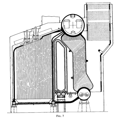
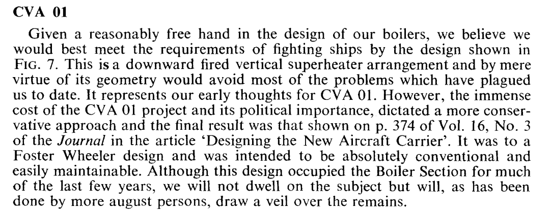
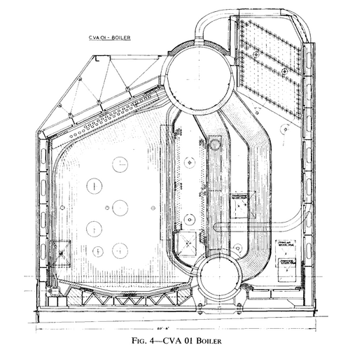
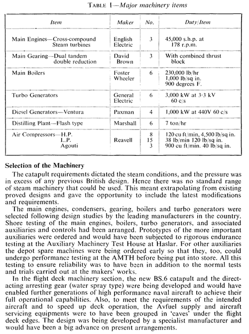
"water spray type" arresting gear?Since CVA-01 seems to come under this thread, I am going to put this here.
View attachment 734927
View attachment 734928
View attachment 734929
View attachment 734930

Boilers
Boilers. December 1967. COMMANDER D. O'HARA, R.N., C.ENG., A.M.I.MECH.E.library.imarest.org

Designing the New Aircraft Carrier
Designing the New Aircraft Carrier. December 1966. COMMANDER J. R. BROADHURST, O.B.E., R.N. (RETD)., C.ENG.library.imarest.org
"water spray type" arresting gear?
So, they filled a large cylinder with water and let the recovered aircraft put force/pressure onto it? Or was that some other way of operating?
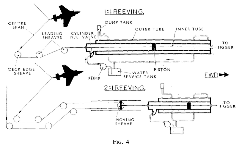
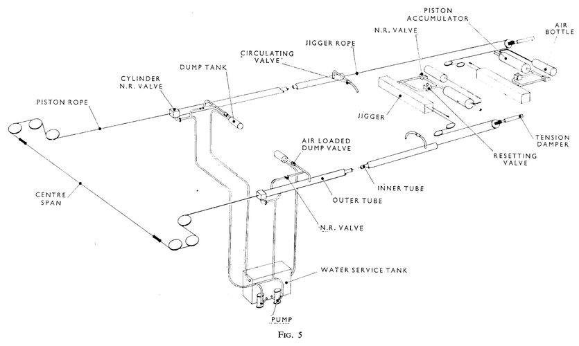
DA 2 Arresting Gear (FIG. 5)
The basic design for the new carrier arresting gear has been retained. The Staff Requirement for this design is to arrest aircraft in the weight range 15,000-40,000 Ib from engaging speeds not less than 110 kts for the lower weight aircraft and not less than 125 kts for the upper weight, without exceeding a retardation of 4-2 g. From ship and equipment considerations the arrest must be completed within a run-out distance of 270 ft, with a deck-edge sheave spacing of 100 ft and with a limiting factor of safety (FOS) of not less than 2 on all arresting gear components. The arresting gear designed and being developed to meet these requirements is the DA2. The essential features of DA2 are:
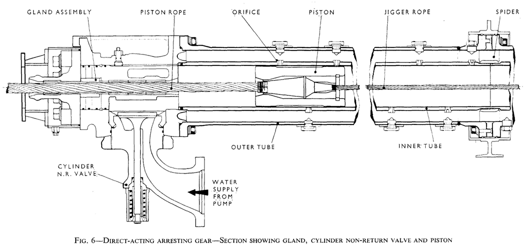
(a) The Energy Absorbing Unit (FIG. 6)
This unit is an inner tube of 5% in. bore contained in a 10 in. bore outer tube and arranged in 2 lines approx. 230 ft long. Along each inner tube are approximately 200 orifices of $ in. diameter. A piston, 12 in. long, connected to the arresting gear rope system runs in each inner tube. Each tube length is anchored at one end only. The tube length is aligned and supported to within a limit of f 0.1 in. over 220 ft and is free to move axially to allow for expansion of the unit or relative ship/unit movement from other causes. The inner and outer tubes are kept full of fresh water by pumps. When the rope system is engaged by the aircraft the pistons are pulled along the inner tubes expelling and circulating the water ahead of each piston through the orifices into the outer tubes and back into the inner tube behind the pistons. Pressures of up to 3,000 lb/sq in. are generated in the inner tubes. Pressures in the outer tubes are controlled to 600 lb/sq in. by air loaded relief valves. As the piston speed decreases during the arrest so does the orifice area ahead of the piston and a reasonably constant pressure and therefore aircraft retardation, is maintained throughout the arrest. By careful design of the orifice programme the gear is capable of arresting a wide range of aircraft weights and speeds and no adjustment of the gear for different aircraft weights and speeds in the specified range is necessary or fitted. The inner and outer tubes are made up from 12 ft and 8 ft lengths as required to match the spacing of the ship's structure. Inner and outer tubes are solid drawn from EN26 and mild steel BS 806-B respectively.
