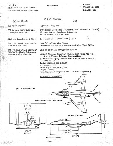
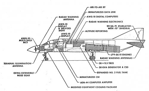
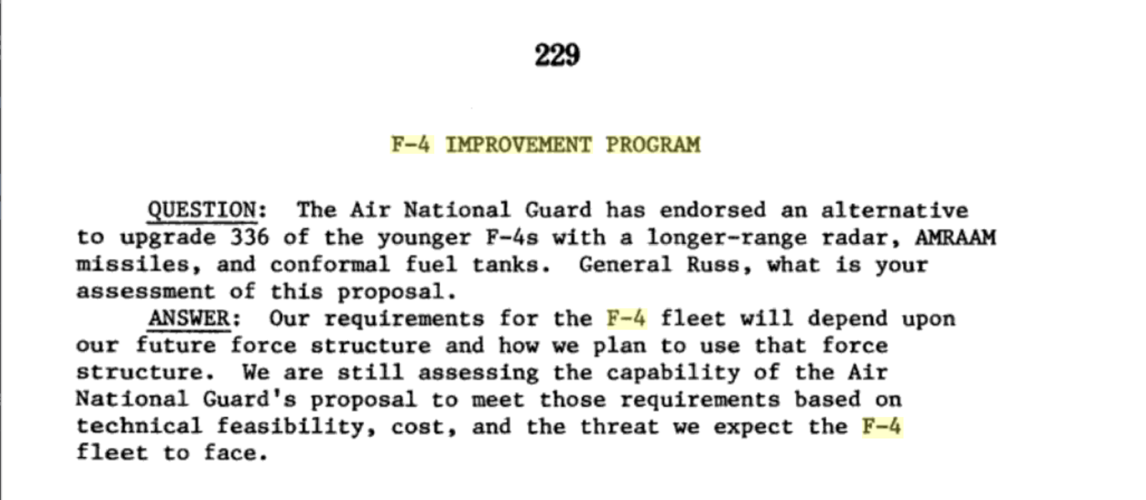
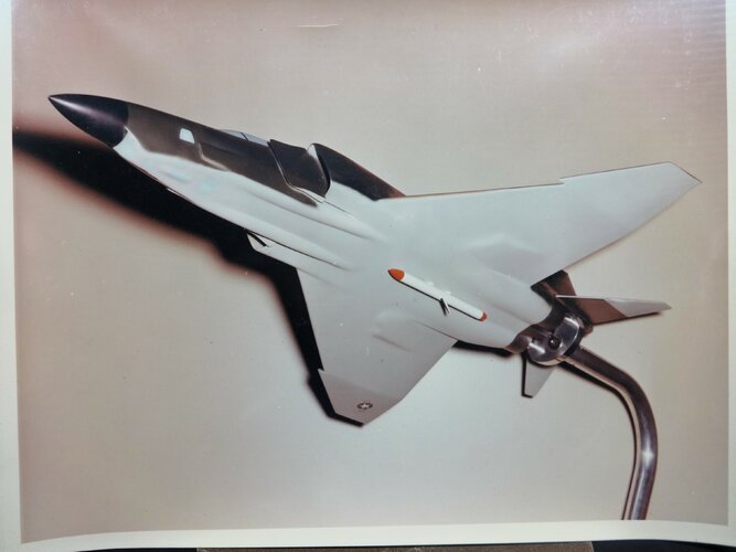
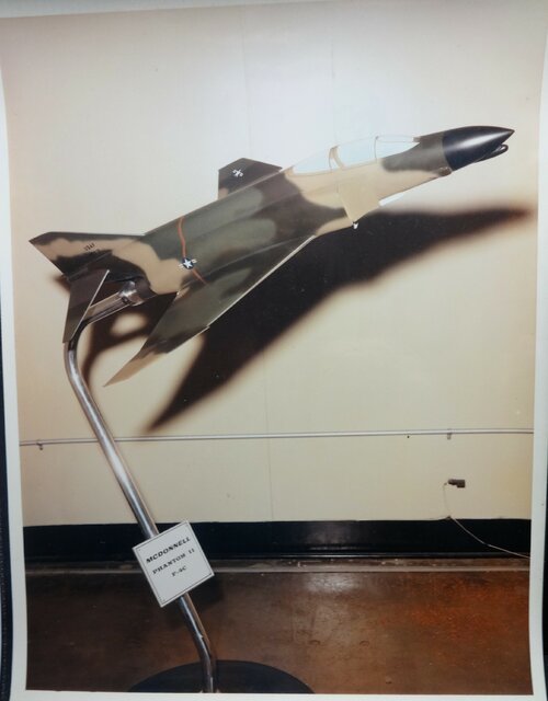
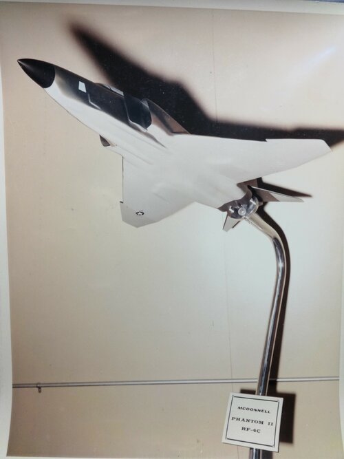
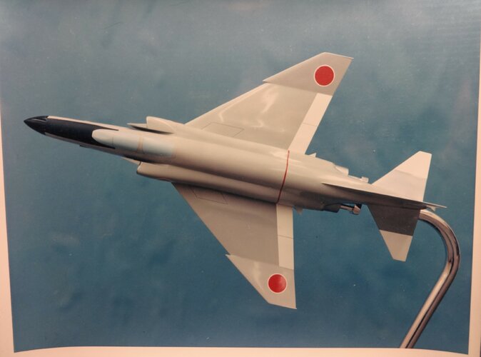
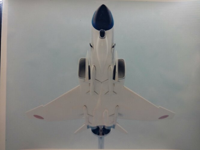
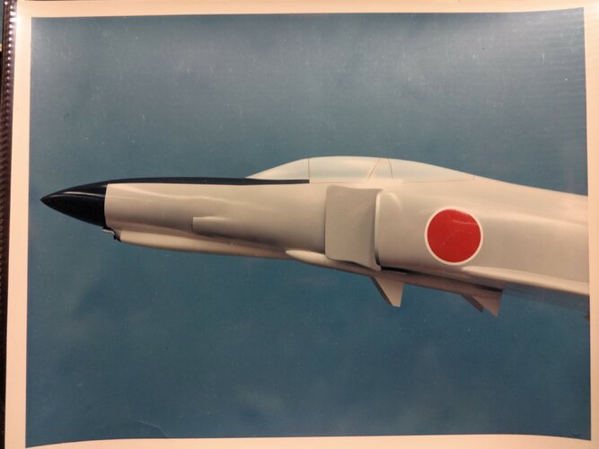
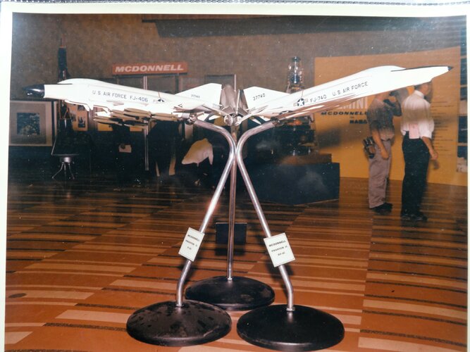
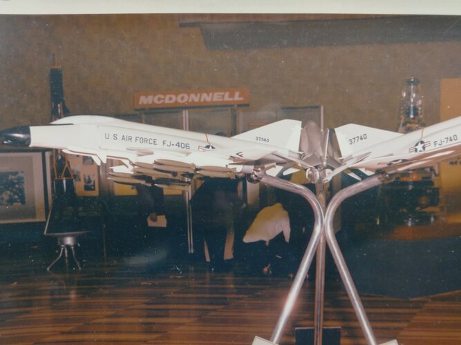
F-4(FV) Proposal from 1965


"Тhis report presents McDonnell Aircraft Corporation's unsolicited proposal
for а three and one-half month, Navy-sponsored program defiinition of the Advanced
F-4B fighter aircraft concept identified as the F-4(FV). Preliminary studies performed
Ьу McDonnell on this and previous configurations have been reviewed Ьу the
Bureau of Naval Weapons. Navy review of McDonnell's preliminary efforts directed
the selection of the F-4(FV) configuration for fighter Weapon System Definition
Study now proposed. Тhе comprehensive study proposed in this report will result
in the development of а program definition to assist the Navy in making а decision
on procurement of an Advanced Fleet Air Defense Weapon System.
The F-4(FV) configuration is considered the optimum design resulting from а
lengthy series of studies conducted Ьу McDonnell's advanced design department.
Аs now conceived, this design offers the Navy а weapon system сараblе of multiple
launches of all-weather guided missiles against an incoming hostile raid plus а
major improvement in carrier suitability, increased radius of action, and maneuverability
as compared to the present F-4.
The scope of effort McDonnell will expend in definition of the F-4(FV)
program is described in this report. Тhе study will Ье а major effort involving
120 engineering personnel, and will Ье managed Ьу the sаme staff responsible for
conception and preliminary studies of this configuration. More than 50% of the
total aircraft advanced design effort during the past three years has been devoted
to а series of F-4 studies applicable and related to the proposed F-4(FV)
study."
 

Attachments

  • F-4 (FV)Technical Proposal.pdf
    1.9 MB · Views: 134
  • F-4-(FV)Technical-Proposal-7.jpg
    F-4-(FV)Technical-Proposal-7.jpg
    494.5 KB · Views: 1,610
  • F-4-(FV)Technical-Proposal-8.jpg
    F-4-(FV)Technical-Proposal-8.jpg
    209.5 KB · Views: 1,604
Mark Nankivil said:
Here's a few more items related to the Mcair proposal to the Navy for the F-4 (FVS). The drawing is from the detail specification and the PDF is a compilation of the airframe specs out of that detail spec.

There's enough info there to help someone come out with a model (hint, hint!).

Enjoy the Day! Mark

Ron Downey said:
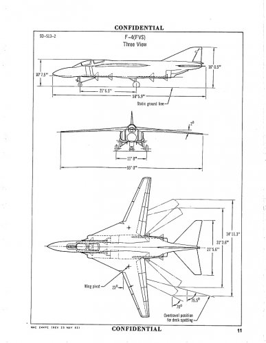
F-4 (FVS) Aircraft Swing Wing Detail Specification

A copy of the McAir report No.SD513-2 on the F-4 FVS Aircraft Swing Wing Detail Specification proposal. Dated 10 August 1966.

From the AeroSpace Project Review:
“In the mid 1960’s, the McDonnell Aircraft Company devoted some internal funds and effort to the F-4(FVS). This would have removed the wing from the F-4 Phantom II and replaced it with an all-new shoulder-mounted swing wing. The target of this enterprise was primarily the US Navy; MAC assured them that the F-4(FVS) would be a superior carrier plane to the standard F-4 due to better low-speed handling characteristics. Howver, while the design seems to have been pretty sound, by this point the Navy wanted a capability the Phantom couldn’t provide: Phoenix missiles. In the end, the Navy largely ignored the F-4(FVS) and went with the F-14. But even then, McDonnell-Douglas proposed a design for the F-14 contest, the Model 225A, that was in part derived from the F-4(FVS) studies.”

See more info here.

Source: http://aviationarchives.blogspot.com/2018/10/f-4-fvs-aircraft-swing-wing-detail.html
 

Attachments

  • 19620525_F-4_FVS_swing_wing_three_view_739x955.jpg
    19620525_F-4_FVS_swing_wing_three_view_739x955.jpg
    125.2 KB · Views: 1,315
Last edited by a moderator:
Mark Nankivil said:
Greetings All -

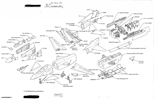
I found another document in the Greater St. Louis Air & Space Museum archives this past weekend covering the F-4 (FVS) proposal. Here is a drawing of the manufacturing breakdown which gives some idea of the make up of the airframe.

Enjoy the Day! Mark

Ron Downey said:
F-4 (FVS) Swing Wing AircraftTech Development Plan
A copy of McAir report E790 on the F-4 FVS Swing Wing AircraftTech Development Plan. Dated 10 August 1966.

Click here to download (5.4 Megs).

Alternate download here.

Source: http://aviationarchives.blogspot.com/2018/10/f-4-fvs-swing-wing-aircrafttech.html
 

Attachments

  • 19660810_F-4_FVS_swing_wing_b&w_picture_665x818.jpg
    19660810_F-4_FVS_swing_wing_b&w_picture_665x818.jpg
    277.9 KB · Views: 1,134
Ron Downey said:
F-4M (FVS) Aircraft Swing Wing Proposal

A copy of the McAir F-4M (FVS) Aircraft Swing Wing Proposal, F378. Dated 24 February 1967.

Click here to download (1.9 Megs).

Alternate download here.

Source: http://aviationarchives.blogspot.com/2018/10/f-4m-fvs-aircraft-swing-wing-proposal.html

Some excerpts, pictures or screenshots from this copy might have been posted in this topic before. :)
 
fightingirish said:
Mark Nankivil said:
Greetings All -

I found another document in the Greater St. Louis Air & Space Museum archives this past weekend covering the F-4 (FVS) proposal. Here is a drawing of the manufacturing breakdown which gives some idea of the make up of the airframe.

Enjoy the Day! Mark

Ron Downey said:
F-4 (FVS) Swing Wing AircraftTech Development Plan
A copy of McAir report E790 on the F-4 FVS Swing Wing AircraftTech Development Plan. Dated 10 August 1966.

Click here to download (5.4 Megs).

Alternate download here.

Source: http://aviationarchives.blogspot.com/2018/10/f-4-fvs-swing-wing-aircrafttech.html

Reminds me of a miniature B-1 Lancer for some reason.
 
fightingirish said:
Ron Downey said:
F-4M (FVS) Aircraft Swing Wing Proposal

A copy of the McAir F-4M (FVS) Aircraft Swing Wing Proposal, F378. Dated 24 February 1967.

Click here to download (1.9 Megs).

Alternate download here.

Source: http://aviationarchives.blogspot.com/2018/10/f-4m-fvs-aircraft-swing-wing-proposal.html

Some excerpts, pictures or screenshots from this copy might have been posted in this topic before. :)

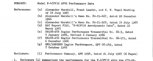
Interesting... "AFVG" .... AFVG was cancelled in June 1967. This brochure is from Feb 1967 but the memo attached seems to show a lot of activity regarding F-4M(FVS) in July 1967.
 

Attachments

  • F-4M(FVS).png
    F-4M(FVS).png
    189.6 KB · Views: 459
On my way to work, so no time to post, but... B)
F-4 (FV) H High Fixed Wing Phantom .
Edit:
Back at home, sitting at my PC, where I can see the full topic and can edit this post. ;)
Mark Nankivil said:
Greetings All -
Some drawings from a McAir brochure on the F-4X. There were also some proposals for a slightly modified wing for the F-4J (called F-4J+).
Enjoy the Day! Mark
Ron Downey said:
F-4X Navy Proposal
A copy of the McDonnell Aircraft F-4X proposal for the US Navy. Report No F333, dated Jan 1967.

From Kim Simmelink’s sources":"The Navy conducted a series of studies which were intended to take the F-4B design (the F-4J was still on the drawing board) into the future and give the Navy a much more capable machine by addressing the Phantoms shortcomings and incorporating state of the art systems. Out of these studies came the F-4(FV) concept. The F-4(FV) had a larger, more advance wing of 640 sq. ft., more advance electronics with multi-track and shoot capability, and the J79-GE-10 engine.

The Navy’s F-4X program (not to be confused with the F-4X program for the Air Force which resulted in the F-4E(S) for Israel) took the work done in the F-4(FV) studies and applied them to the upcoming F-4J looking at five different design variations which would take the design into the next century as a viable fleet defender.

The first variation is (referred to as the F-4J+) which was a minimum change of the upcoming F-4J. Improvements were made to the wing, and high lift devices, the catapult performance, and it was to be equipped with a modified AWG-10 with multi-shot capability for the AIM-7F Sparrow III missile.

Next was the F-4(FV)L which built on the F-4J+ with an improved wing (still mounted at the same place as the F-4J) which had increased wing area of 595 sq. feet, improved lift devices (including slats) and better carrier suitability.

The F-4(FV)H was a high wing variation of the F-4(FV)L which had modified main landing gear and lower fuselage, a thinner wing of 560 sq. ft., and offered more growth potential because of changes to the internal volume.

The F-4(FV)S was a revision of the F-4(FVS) proposed earlier by McDonnell, and increased the size of the wing from 420 sq. ft. on the F-4(FVS) to 500 sq. ft. This wing offered improved maneuverability and lower approach speeds. It still retained BLC on the trailing edge flaps. This design had a larger stabilator and vertical tail to improve stability.

The final design study was the F-4(FV)S with an advanced engine. This design would incorporate the increase area intakes of the F-4K along with the General Electric GE-1 engine. This design would have improved approach speeds, service ceiling, and acceleration time.

These studies were a last gasp to breathe new life into the F-4 airframe. But it was already showing its age and newer, more capable aircraft were soon to make it less likely that any serious consideration would be paid to these designs. Some improvements were taken from the studies and incorporated into the F-4S upgrade of the F-4J."

Alternate download here.

Source: http://aviationarchives.blogspot.com/2018/10/f-4x-navy-proposal.html
 
Last edited by a moderator:
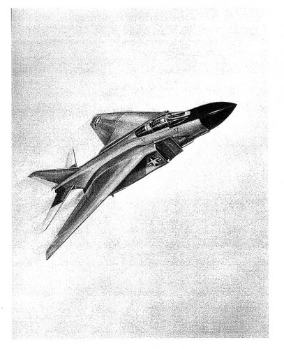
Found this on the Aviation Archives site. Don't know if it was an actual proposal or not but thought it was interesting. No further information on the website unfortunately.

http://aviationarchives.blogspot.com/2014/01/f-4-line-drawings.html
 

Attachments

  • Scan-140122-0003[2].jpg
    Scan-140122-0003[2].jpg
    124.7 KB · Views: 933
RAP said:
Found this on the Aviation Archives site. Don't know if it was an actual proposal or not but thought it was interesting. No further information on the website unfortunately.

http://aviationarchives.blogspot.com/2014/01/f-4-line-drawings.html

Really lovely charcoal line pictures, especially the one you included here.
Other charcoal pictures at the link appear to be standard F-4s, no indication that this picture wasn't just an artists flight of artistic enthusiasm.
 
98MQ F-4E with F-15 systems (1969)
98MS F-4E with F-15 wing (1969)

Does anyone have anymore information on these proposals, pictures or drawings maybe?
 
While not a Phantom specific program, this is interesting none the less:
The idea of the Alternative Aircraft Takeoff System (AATS) originated at the Flight Dynamics Laboratory at Wright-Patterson Air Force Base in Dayton, OH. AATS called for the development of a ground-effect vehicle to serve as a support platform enabling combat aircraft to take off from bombed or otherwise damaged runways.

The unmanned hover platform would use its own power for ground effect ascension only; the aircraft's jet engine or engines would accelerated both the plane and the AATS to takeoff speeds. On actual take-off, the aircraft's wheels would leave the wells built into the hover platform and drogue parachutes would deploy automatically to slow and eventually halt the AATS for retrieval.

Photograph of 1/10-scale F-4 mockup, borrowed from the Navy, and AATS used by Bell Aerospace for wind tunnel testing.

"Airborne from the Ground Up" Popular Mechanics September 1981
aatsmockup-jpg.97048
 
Hey guys,

I found some interesting Congressional reports about upgrading the F-4D into a more capable air defense fighter circa 1988. They planned on installing new APG-63 and old IRST's from scrapped F-106's, an odd combo, along with conformal fuel tanks and potential re-engining of some kind of 180 fighters. Any notion of F-4D mods were squashed due to excessive cost, airframe life, extensive rewiring, and extending the nose 18 inches to accommodate the new radar. Modified F-16A's were better in every metric.

1987 Cost analysis

1988 DoD appropriations

GAO F-16 vs F-4D comparison letter
 
Here are some fascinating details on what the Israeli Super Phantom could have been. Mach 3 plus, supercruise without afterburners. and a better than 1:1 power to weight ratio. It would have been quite a beast.


Not sure where else to put this regarding the GAU-9, but digging deeper into the Conformal Carriage program ran by the Navy I found that a one point a gun pod was to be developed for it.
Found on DTIC, it's a great read:

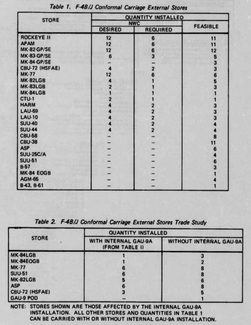
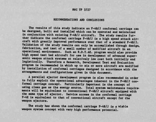
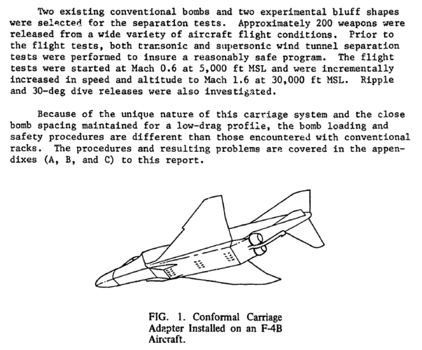
F-4B/J Aircraft Conformal Carriage Preliminary Design Study Report
https://apps.dtic.mil/dtic/tr/fulltext/u2/b002789.pdf
Two conformal carriage configurations have been developed. One configuration Includes two permanently Installed GAU-9A 30 mm guns with associated ammunition storage. An alternate configuration contains modular ECM and Pave Spike equipment In the fwd fairing and provision Is made for Installation of the GAU-9 30 mm gun pod. This latter con- figuration Is recommended for an R.D.T.&E. program.
The Installation of GAU-9A guns and associated ammunition storage containers requires a deeper conformal carriage configuration which changes the relationship of external stores and the catapult bridle. In some cases stores which would be hit by the catapult bridle If the conformal carriage were deep enough to contain the GAU-9A guns would not be affected by the bridle were the conformal carriage only deep enough for the weapon ejectors. The external stores so affected are listed In Table 2.
The conformal carriage installation can be more versatile if the GAU-9A 30-mm gun is carried as an external pod instead of infernally.
The GAU-9 gun pod resembles the existing MK-4 gun pod and could be carried at the centerline 30-inch weapon ejector position. Maintenance of gun boresight pointing could be assured by pod sway brace supports at the forward and aft end of the pod.
Screen Shot 2021-05-07 at 2.40.19 PM.png
 
Last edited by a moderator:
Some very interesting images in that report
It certainly has some interesting implications. The Navy was interested in getting a permeant gun on their Phantoms in 30mm no less, a few of the listed weapons were Air Force projects like EOGB (GBU-8/15) instead on the Navy's Walleye.
 
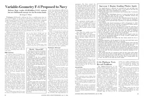
Phantom FV Challenging F-111B

Another major innovation projected for the FV is a discriminatory multi-shot fire-control system (see Sensor, December 16) with a capacity to lock on to as many as six targets simultaneously. The most threatening target at any one time is selected automatically for attack and the process continues in a descending order of threat.

So can we ascertain what this radar might have been?

Regards
Pioneer
 
Phantom FV Challenging F-111B

Another major innovation projected for the FV is a discriminatory multi-shot fire-control system (see Sensor, December 16) with a capacity to lock on to as many as six targets simultaneously. The most threatening target at any one time is selected automatically for attack and the process continues in a descending order of threat.
So can we ascertain what this radar might have been?

Regards
Pioneer

Judging by the post below, a modified version of the AWG-10.

F-4(FV) Proposal from 1965

 
On my way to work, so no time to post, but... B)
F-4 (FV) H High Fixed Wing Phantom .
Edit:
Back at home, sitting at my PC, where I can see the full topic and can edit this post. ;)
Mark Nankivil said:
Greetings All -
Some drawings from a McAir brochure on the F-4X. There were also some proposals for a slightly modified wing for the F-4J (called F-4J+).
Enjoy the Day! Mark
Ron Downey said:
F-4X Navy Proposal
A copy of the McDonnell Aircraft F-4X proposal for the US Navy. Report No F333, dated Jan 1967.

From Kim Simmelink’s sources":"The Navy conducted a series of studies which were intended to take the F-4B design (the F-4J was still on the drawing board) into the future and give the Navy a much more capable machine by addressing the Phantoms shortcomings and incorporating state of the art systems. Out of these studies came the F-4(FV) concept. The F-4(FV) had a larger, more advance wing of 640 sq. ft., more advance electronics with multi-track and shoot capability, and the J79-GE-10 engine.

The Navy’s F-4X program (not to be confused with the F-4X program for the Air Force which resulted in the F-4E(S) for Israel) took the work done in the F-4(FV) studies and applied them to the upcoming F-4J looking at five different design variations which would take the design into the next century as a viable fleet defender.

The first variation is (referred to as the F-4J+) which was a minimum change of the upcoming F-4J. Improvements were made to the wing, and high lift devices, the catapult performance, and it was to be equipped with a modified AWG-10 with multi-shot capability for the AIM-7F Sparrow III missile.

Next was the F-4(FV)L which built on the F-4J+ with an improved wing (still mounted at the same place as the F-4J) which had increased wing area of 595 sq. feet, improved lift devices (including slats) and better carrier suitability.

The F-4(FV)H was a high wing variation of the F-4(FV)L which had modified main landing gear and lower fuselage, a thinner wing of 560 sq. ft., and offered more growth potential because of changes to the internal volume.

The F-4(FV)S was a revision of the F-4(FVS) proposed earlier by McDonnell, and increased the size of the wing from 420 sq. ft. on the F-4(FVS) to 500 sq. ft. This wing offered improved maneuverability and lower approach speeds. It still retained BLC on the trailing edge flaps. This design had a larger stabilator and vertical tail to improve stability.

The final design study was the F-4(FV)S with an advanced engine. This design would incorporate the increase area intakes of the F-4K along with the General Electric GE-1 engine. This design would have improved approach speeds, service ceiling, and acceleration time.

These studies were a last gasp to breathe new life into the F-4 airframe. But it was already showing its age and newer, more capable aircraft were soon to make it less likely that any serious consideration would be paid to these designs. Some improvements were taken from the studies and incorporated into the F-4S upgrade of the F-4J."

Alternate download here.

Source: http://aviationarchives.blogspot.com/2018/10/f-4x-navy-proposal.html
Do not click on "Click here to download (6.7Megs)". It will ruin your day.
 
Last edited by a moderator:
On my way to work, so no time to post, but... B)
F-4 (FV) H High Fixed Wing Phantom .
Edit:
Back at home, sitting at my PC, where I can see the full topic and can edit this post. ;)
Mark Nankivil said:
Greetings All -
Some drawings from a McAir brochure on the F-4X. There were also some proposals for a slightly modified wing for the F-4J (called F-4J+).
Enjoy the Day! Mark
Ron Downey said:
F-4X Navy Proposal
A copy of the McDonnell Aircraft F-4X proposal for the US Navy. Report No F333, dated Jan 1967.

From Kim Simmelink’s sources":"The Navy conducted a series of studies which were intended to take the F-4B design (the F-4J was still on the drawing board) into the future and give the Navy a much more capable machine by addressing the Phantoms shortcomings and incorporating state of the art systems. Out of these studies came the F-4(FV) concept. The F-4(FV) had a larger, more advance wing of 640 sq. ft., more advance electronics with multi-track and shoot capability, and the J79-GE-10 engine.

The Navy’s F-4X program (not to be confused with the F-4X program for the Air Force which resulted in the F-4E(S) for Israel) took the work done in the F-4(FV) studies and applied them to the upcoming F-4J looking at five different design variations which would take the design into the next century as a viable fleet defender.

The first variation is (referred to as the F-4J+) which was a minimum change of the upcoming F-4J. Improvements were made to the wing, and high lift devices, the catapult performance, and it was to be equipped with a modified AWG-10 with multi-shot capability for the AIM-7F Sparrow III missile.

Next was the F-4(FV)L which built on the F-4J+ with an improved wing (still mounted at the same place as the F-4J) which had increased wing area of 595 sq. feet, improved lift devices (including slats) and better carrier suitability.

The F-4(FV)H was a high wing variation of the F-4(FV)L which had modified main landing gear and lower fuselage, a thinner wing of 560 sq. ft., and offered more growth potential because of changes to the internal volume.

The F-4(FV)S was a revision of the F-4(FVS) proposed earlier by McDonnell, and increased the size of the wing from 420 sq. ft. on the F-4(FVS) to 500 sq. ft. This wing offered improved maneuverability and lower approach speeds. It still retained BLC on the trailing edge flaps. This design had a larger stabilator and vertical tail to improve stability.

The final design study was the F-4(FV)S with an advanced engine. This design would incorporate the increase area intakes of the F-4K along with the General Electric GE-1 engine. This design would have improved approach speeds, service ceiling, and acceleration time.

These studies were a last gasp to breathe new life into the F-4 airframe. But it was already showing its age and newer, more capable aircraft were soon to make it less likely that any serious consideration would be paid to these designs. Some improvements were taken from the studies and incorporated into the F-4S upgrade of the F-4J."

Alternate download here.

Source: http://aviationarchives.blogspot.com/2018/10/f-4x-navy-proposal.html
Do not click on "Click here to download (6.7Megs)". It will ruin your day.

I removed the link in question, but it isn't a virus or anything - its just a hosting site often used for copyright infringement flagged incorrectly I think.

File is now attached here.
 

Attachments

  • F-4X Navy Proposal.pdf
    3.5 MB · Views: 160
On my way to work, so no time to post, but... B)
F-4 (FV) H High Fixed Wing Phantom .
Edit:
Back at home, sitting at my PC, where I can see the full topic and can edit this post. ;)
Mark Nankivil said:
Greetings All -
Some drawings from a McAir brochure on the F-4X. There were also some proposals for a slightly modified wing for the F-4J (called F-4J+).
Enjoy the Day! Mark
Ron Downey said:
F-4X Navy Proposal
A copy of the McDonnell Aircraft F-4X proposal for the US Navy. Report No F333, dated Jan 1967.

From Kim Simmelink’s sources":"The Navy conducted a series of studies which were intended to take the F-4B design (the F-4J was still on the drawing board) into the future and give the Navy a much more capable machine by addressing the Phantoms shortcomings and incorporating state of the art systems. Out of these studies came the F-4(FV) concept. The F-4(FV) had a larger, more advance wing of 640 sq. ft., more advance electronics with multi-track and shoot capability, and the J79-GE-10 engine.

The Navy’s F-4X program (not to be confused with the F-4X program for the Air Force which resulted in the F-4E(S) for Israel) took the work done in the F-4(FV) studies and applied them to the upcoming F-4J looking at five different design variations which would take the design into the next century as a viable fleet defender.

The first variation is (referred to as the F-4J+) which was a minimum change of the upcoming F-4J. Improvements were made to the wing, and high lift devices, the catapult performance, and it was to be equipped with a modified AWG-10 with multi-shot capability for the AIM-7F Sparrow III missile.

Next was the F-4(FV)L which built on the F-4J+ with an improved wing (still mounted at the same place as the F-4J) which had increased wing area of 595 sq. feet, improved lift devices (including slats) and better carrier suitability.

The F-4(FV)H was a high wing variation of the F-4(FV)L which had modified main landing gear and lower fuselage, a thinner wing of 560 sq. ft., and offered more growth potential because of changes to the internal volume.

The F-4(FV)S was a revision of the F-4(FVS) proposed earlier by McDonnell, and increased the size of the wing from 420 sq. ft. on the F-4(FVS) to 500 sq. ft. This wing offered improved maneuverability and lower approach speeds. It still retained BLC on the trailing edge flaps. This design had a larger stabilator and vertical tail to improve stability.

The final design study was the F-4(FV)S with an advanced engine. This design would incorporate the increase area intakes of the F-4K along with the General Electric GE-1 engine. This design would have improved approach speeds, service ceiling, and acceleration time.

These studies were a last gasp to breathe new life into the F-4 airframe. But it was already showing its age and newer, more capable aircraft were soon to make it less likely that any serious consideration would be paid to these designs. Some improvements were taken from the studies and incorporated into the F-4S upgrade of the F-4J."

Alternate download here.

Source: http://aviationarchives.blogspot.com/2018/10/f-4x-navy-proposal.html
Do not click on "Click here to download (6.7Megs)". It will ruin your day.

I removed the link in question, but it isn't a virus or anything - its just a hosting site often used for copyright infringement flagged incorrectly I think.

File is now attached here.
Thank you Paul, I am glad if was no problem. It certainly set off every bell and whistle on my computer, and locked me out from closing the link. Anyway, thank you very much!
 
In relation to the the Boeing Conformal Weapons Carriage / F-4 Phantom II configuration, I stumbled across the following interesting website:


Notable for me is the great profiling artwork (including the 'Bluff Bomb' concept)!!

Regards
Pioneer

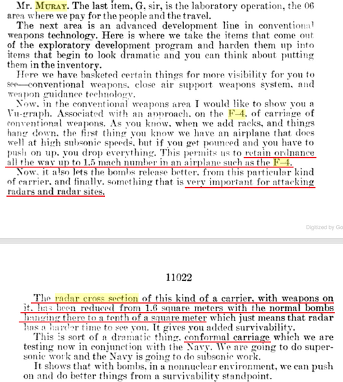
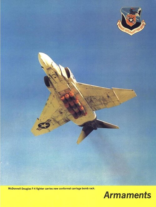
A Congress hearing on 9 Feb 1972 shows that the F-4 with conformal bombs could go as fast as Mach 1.5 and the RCS of conformal carriage itself was reduced to 0.1 m2 from 1.6 m2 of conventional carriage.

Since Range2 / Range1 = ( RCS2 / RCS1 ) ^ 0.25,

Range(0.1) / Range(1.6) = ( 0.1 / 1.6 ) ^ 0.25

Range(0.1) / Range(1.6) = 0.5

Range(0.1) = 0.5 x Range(1.6)

That means the conformal carriage will reduce the range at which it is detected by a threat radar by 50%.

Of course, because the conformal carriage has to be attached underneath the F-4, overall reduction in detection range is hard to know.

conformal-bomb-rack.png

Link

F-4B_conformal.PNG
 

Attachments

  • conformal_carriage.pdf
    3 MB · Views: 49
Last edited:
A Congress hearing on 9 Feb 1972 shows that the F-4 with conformal bombs could go as fast as Mach 1.5 and the RCS of conformal carriage itself was reduced to 0.1 m2 from 1.6 m2 of conventional carriage.

Since Range2 / Range1 = ( RCS2 / RCS1 ) ^ 0.25,

Range(0.1) / Range(1.6) = ( 0.1 / 1.6 ) ^ 0.25

Range(0.1) / Range(1.6) = 0.5

Range(0.1) = 0.5 x Range(1.6)

That means the conformal carriage will reduce the range at which it is detected by a threat radar by 50%.

Of course, because the conformal carriage has to be attached underneath the F-4, overall reduction in detection range is hard to know.

View attachment 690885

Link

View attachment 690886
Thank you for the additional info datafuser.

Regards
Pioneer
 
Could be Westinghouse Co - they made serious radars...
 
WECO is Western Electric Company I think. They made radars. That's all I've found.
Western Electric was the manufacturing arm of the Bell Telephone System (later AT&T). They were the production counterpart to Bell Labs, which was the research and development arm of the company (where I once worked). Bell System involvement with radar was news to me, but not a surprise, given the range of work done at Bell Labs.

See:
https://industrialscenery.blogspot.com/2015/11/western-electric-manufactured-radar.html
https://en.wikipedia.org/wiki/AN/TPS-1
 

Similar threads

Please donate to support the forum.

Back
Top Bottom