The known harrier versions are GR1, GR3,GR5, GR7 and GR9.
What happend with GR2,GR4,GR6,GR8?
are they skipped? are they concepts that didn't work?
If they were concepts, does photo's of these concepts still exist? (please post on this thread)
 
This question was answered 16 years ago via Harrier.org :

"The Harrier T Mk 6 designation was allocated to a version of the Harrier I
trainer (T.2/T.4) upgraded to train Harrier II GR.5/GR.7 pilots, with a
FLIR in place of the LRMTS plus avionics updates etc. However, the
decision to purchase the T Mk 10 obviated the need for it. The latter was
ordered as it was a more realistic to train Harrier II pilots on these,
and it also saved the logistics costs of operating old trainers alongside
new single seaters. "

I've merged it with this older thread, though the T.6 obviously wasn't advanced
enough back then. ;)
 
And thus... What was the Harrier Mk.8 then ? another trainer, this time for the GR.9 ?
 
(Sorry Administrators, I was unable to find a specific Hawker-Siddeley Harrier development thread to post this question - so if you know of one, please feel to move to a more appropriate thread!)


A technical question in relation to the Harrier GR.1 if I may to the forum please:

I've just read The Harrier Story by Peter E. Davies and Anthony M. Thornborough, in which it states that 'the Harrier GR.1 was designed to facilitate bolt-on extra length wing tips to improve the cursing range of the aircraft, by some 11 per cent. However, the use of the bolt-on extra length wing tips seems to have only been used in May 1969; when Harrier's XV741 and XV744 took part in the Daily Mail newspapers Transatlantic Air Race, the race being the fastest return crossing between the city centres of London and New York.'
Interestingly, the author also states 'it is unlikely that these bolt-on extra length wing tips were ever used operationally.'

My questions to the forum is as follows:

a/ What was the span of these 'bolt-on extra length wing tips'?

b/ What was the reason that they would have only been applied for ferry flight, as opposed to normal operational flights?
Did they impose a detrimental effect on the Harrier's normal flight characteristics?

Given the Hawker-Siddeley estimate of an 11 per cent increase in range with the employment of these bolt-on wing tips, the following ranges could theoretically be obtained by the Harrier GR.3:

670 km (410 miles) ho-lo-hi with 4,400 lb (1,996 kg) payload

(+11 per cent = 744 km (455 miles))

370 km (230 miles) lo-lo with 4,400 lb (1,996 kg) payload

(+11 per cent = 411 km (255 miles))

At the end of the day, one would think given the appreciated limited operational range of the Harrier GR.1/GR.3 design, any increase in operational range wouldn't have been scoffed at and yet they weren't employed....

Regards
Pioneer
 
The Harrier entered RAF service in April 1969 and was immediately entered for the Daily Mail Air Race. The race was to commemorate the 50th anniversary of the 49 first crossing of the Atlantic by Alcock and Brown in a Vickers Vimy. On 5 May 1969 Sqn Ldr Tom Lecky-Thompson ran from the top of the Post Office Tower in central London to a helicopter which took him to St Pancras railway station where he took off vertically in a Harrier GR1 (XV741). He refuelled at Mach 0.88 from a Victor tanker; landed vertically at Bristol Basin in Manhattan and roared through New York on a motor bike to reach the top of the Empire State Building in the winning time of 6 hours, 11 minutes and 57.15 seconds. Sqn Ldr Graham Williams flew the return leg on 9 May in XV744 using an E-Type Jaguar in New York and landed in a cloud of coal dust at St Pancras before a helicopter and motor bike took him to the top of the Post Office Tower just 5 hours, 49 minutes and 58 second after leaving the top of the Empire State Building. This gave great publicity to the Harrier, particularly in America where it was their first real exposure to the aircraft. The Air Race was the only time I can recall that the ferry tips were used. These eighteen-inch extensions were bolted on to the wing tips – ‘cheap variable geometry’ John Fozard called them – and gave improved cruise performance at height but carried limitations that precluded their use for low level operations.
Our Chairman has reminded us that it was the aircraft’s unique flexibility that allowed it to be deployed to Belize in 1975. Indeed, the Harrier was the only combat aircraft in front-line service capable of operating from the short single runway at Belize Airport. In response to the Guatemalan threat of invasion, No 1 Sqn was placed at seven day’s notice to move on its return in October of that year from an APC at Decimomannu. Following a short period of frantic preparation, the squadron deployed six aircraft with Victor tanker support to Belize via Goose Bay and Bermuda. Of interest, because of Fidel Castro’s support for Belizean independence and his stance, therefore, against Guatemala, the squadron was denied US landing rights and facilities. In preparing for the deployment, Peter Taylor had argued strongly against the use of ferry wing tips which would delay generating the aircraft for operations on arrival. He won the debate and the first two aircraft were airborne again on CAP within twenty minutes of landing.

 
When the Sea Harrier F/A 2 was being developed, the ferry-tip idea was revisited as a measure to counter the expected destabilising effects of underwing AMRAAMs. The AMRAAM tips were a lot smaller than the original ferry tips and got as far as flight test with correct shape but non-production structure. In the event, they were not needed as the rear fuselage extension restored the stability.
 
Thank you gentlemen for your replies.

Regards
Pioneer
 
I think this is probably the best thread, although is more around the Harrier I timescale in the early 60s

In issue 40 of TAH, there's an article on Hawker P.1163 / HS.1170 which seems to be basically a Harrier I with a BS.94/5 engine (BS.75 derivative) rather than anything to do with P.1154. There's few details on performance though besides Mach 1.7 at altitude.

I assume that BS.94/5 was a refanned BS.75 with larger bypass ratio for increased dry thrust, and then PCB for lots more thrust. I think best comparison is against the contemporary Pegasus 5 which had 15,000lbf Vs 19,000lbf for the BS.94/5. I assume from a physically smaller and lighter engine. So I'd expect better climb, acceleration, max speed, sustained turn and bring back performance. But with added complexity of PCB.
 
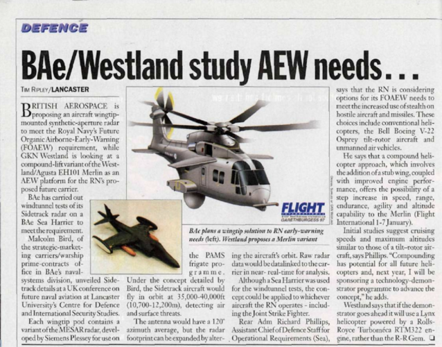
I was able to track down the original article about the Harrier AEW. It was published in Flight International March 19-25, 1997 issue.

According to the article, it was a proposal made by British Aerospace for the Royal Navy's Future Organic Airborne-Early-Warning (FOAEW) requirement.

Each wingtip pod contained a variant of the MESAR radar developed by Siemes Plessey. The radar antenna had a 120º azimut and the aircraft would orbiting at 35,000 - 40,000 ft (10,700 - 12,200 m) above the patrol area.

Also, it mentions that a Sea Harrier was used as a model for the wind tunnel test, but the system could be fitted into the Joint Strike Fighter as well.

Here is the full article:
Flight_International_n4566_v151_1997.png
 
I believe there is an small image of a Boeing F-32 with original delta wings with these wingtip pods in a Flight article about JSF or CVF.
 
If I could pick forum members brains please....

On another forum, someone is asking the following question in relation to the Harrier:

I'm having a bit of a brain fart and was wondering if anyone could help me? I remember reading about a British development of a twin seat harrier for night strike roles, but I can't remember what the project was called or what modifications were to be made. I think it was drafted in the early 1980's?

Does anyone have any knowledge or insight into such an study?

Regards
Pioneer
 
I recall seeing a photo of or an article about a night attack Harrier. A T10 with all sorts of kit on it. Night Owl or something.

Can't find it, but will keep looking.

Chris
 
Of course most of the Harrier trainers were combat capable anyway.
If it was early 1980s it sounds like early thoughts connected with the GR.5/T.10.
 
I recall seeing a photo of or an article about a night attack Harrier. A T10 with all sorts of kit on it. Night Owl or something.

Can't find it, but will keep looking.

Chris
Thank you Chris, if you would.

Regards
Pioneer
 
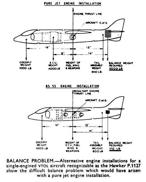
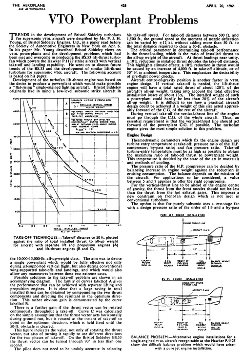
From Aeroplane 1961,

so weird,please read the caption.
I don't understand what is weird here. The article and drawing make the following argument:

For VTOL, the engine thrust has to be distributed around the aircraft's center of gravity, as shown for both the theoretical, pure-turbojet design and the Kestrel/Harrier turbofan design. Otherwise, the aircraft would flip over rather than rising with the airplane horizontal.

The pure turbojet design can only produce thrust at the hot, rear end of the engine. So the turbojet has to be in the front end of the fuselage, where its weight is far from the center of gravity and must therefore be balanced by ballast at the rear.

The Kestrel/Harrier design's turbofan produces thrust from both the front/fan end of the engine and from the hot, pure-jet end at the rear. So the turbofan can straddle the center of gravity, perfectly balanced, with no need for ballast.
 
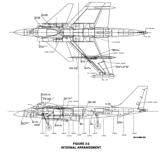
Hi, While reading the posts about VFA-Fighters for Sea Control Ships, I came across the mention of the McDonnell Douglas Model 258-52. Powered by a Pegasus 15-03, a redefined fuselage and high speed wing, and F-4J intakes. Has anyone ever seen a 3 view drawing of this design? To me, it sounds similar to the AV-8SX that Mcdonnell Douglas was proposing as a supersonic demonstrator,but that was in the 1980's.
thanks for help. :)
Search this web site for 279-3 and 279-4. McDonnell designs that came after the AV-8SX. AV-8SX was an attempt to create a supersonic capable AV-8 variant. To accomplish this, after-burning (Called plenum chamber burning) in the forward pair of nozzles was devised. The concept was tested full-size at Shoeburyness, UK in 1981. Stated simply, it didn't work. Inlet location on the sides of the fuselage near the rising plume of hot gas underneath result in substantial loss of net thrust. The 279 series hoped to reduce this effect with auxiliary inlets, lower body "fences" to control upwelling flow and adjustment of the overall planform (canard vs wing/tail).
 
I must mention that we knew a Mr. Rowe who led team that solved this Harrier problem: Even though the solution was not used, the project cancelled, he was still bound by NDA. But, when I mentioned 'Plenum Chamber Burning', he laughed, indicated that PCB was a dead-end. As you say, PCB had 'issues'...

How did his people solve it ?? We may have to wait another decade or three for the National Archives to reveal configuration...
--
I've since wondered if they'd devised a twin-engine format, engines stacked vertically like EE Lightning, but offset lengthwise. The Lower, front engine's bypass feeds front side nozzles as-is. No PCB. Its Exhaust, mixed and safely cooled by upper, aft engine's bypass, feeds rear side nozzles. Upper engine exhausts at tail, via after-burner for supersonic. And, perhaps, thrust deflector for when after-burn is off...

Yes, a brute, but I'm sure the RAF, RN and USMC would have loved it...
 
Very interesting to read about all the complicated compromises they had to make to get a supersonic Pegasus... and the airframe around it was even worse. Mirage intakes but huge because big compressor ,while the rear fuselage is so fat it needs a long tail to recover some kind of area rule... and the Pegasus grouped exhausts for VSTOL...
Love the AV-8SX too.
 
I don't think anyone ever has solved the problem of hot-gas reingestion have they?
If they did that technology certainly didn't seem to find its way into the stock Harrier for example.

I suppose if you had a stream of high-pressure bleed air you might be able to lessen the effect but once you get deeper into ground effect I can't see an easy way to stop the hot air rebounding off the ground.

Boeing's JSF had that sort of a jet screen to reduce reingestion. It doesn't seem like it worked well enough.
 
In the end, it's solved by rolling forward, which is less like conventional landing now and more like conventional landing in a biplane. Where forward speeds might be less than 30kts.
 
Boeing's JSF had that sort of a jet screen to reduce reingestion. It doesn't seem like it worked well enough.
I suspect it would have worked fine onboard ship, where the ship can put 30 knots of wind over the deck. But they always tested things over land first...

In the end, as much as I hate the extra complexity (and chance of failure, seen at least one F-35 have a liftfan failure on camera), the Liftfan was the way to go. Unless we can convince someone to play with a P1214 or P1216 PCB triple nozzle...
 
I recall seeing a photo of or an article about a night attack Harrier. A T10 with all sorts of kit on it. Night Owl or something.

Can't find it, but will keep looking.

Chris

Of course most of the Harrier trainers were combat capable anyway.
If it was early 1980s it sounds like early thoughts connected with the GR.5/T.10.

The USMC made a "Night Attack" variant of the AV-8B in 1987... but it was the normal single-seat AV-8B with infrared sensors, cockpit illumination compatable with NVGs, and other such. 66 AV-8B(NA) were built and delivered from September 1989 on.

The RAF's GR.5 (their version of the AV-8B) also received those night attack upgrades (becoming GR.7s).

There was a 2-seat Harrier II - the USMC bought 28 TAV-8Bs, but these were solely for training use.
 
Unless we can convince someone to play with a P1214 or P1216 PCB triple nozzle...
The concept was tested full-size at Shoeburyness, UK in 1981. Stated simply, it didn't work. Inlet location on the sides of the fuselage near the rising plume of hot gas underneath result in substantial loss of net thrust.
The 279 series hoped to reduce this effect with auxiliary inlets, lower body "fences" to control upwelling flow and adjustment of the overall planform (canard vs wing/tail).

So PCB could be made to work, but only through a very radical design of the airframes around it ? classic Harrier, supersonic would NOT work (hello, P.1154 !)

And the 279 was the American try, when the P.1216 was the British taking their chance ?

Which design would be best ? the 279 or the P.1216 ?
 
So PCB could be made to work, but only through a very radical design of the airframes around it ? classic Harrier, supersonic would NOT work (hello, P.1154 !)
I'm assuming that a P1214/1216 would have either LIDS strakes or gun pods like the AV8B to help trap hot gasses.


And the 279 was the American try, when the P.1216 was the British taking their chance ?

Which design would be best ? the 279 or the P.1216 ?
P1214! forward swept wings makes for a smaller footprint onboard ship, even if you don't get any maneuverability bonuses.
 
Regarding the P.1154, it never even got off the drawing boards Archibald. The RAF and RN were not interested at the time because of the F-4 Phantom.
 
Thanks Zen, I did not know that Hawker had a P.1154 prototype 33% complete by the time it was canceled. Another one of my favourite what might have been projects.
 
I suspect it would have worked fine onboard ship, where the ship can put 30 knots of wind over the deck. But they always tested things over land first...

In the end, as much as I hate the extra complexity (and chance of failure, seen at least one F-35 have a liftfan failure on camera), the Liftfan was the way to go. Unless we can convince someone to play with a P1214 or P1216 PCB triple nozzle...
Ships could conceivably launch and recover a PCB VTOL airplane without wind over the deck if they had a perforated launch and landing platform or grid that folded out over the water.
 
Boeing's JSF had that sort of a jet screen to reduce reingestion. It doesn't seem like it worked well enough.
Now…if you had a saucer like craft with a big central impeller…might that also cool the exhaust if it gets caught up in an inner doughnut with the outermost blades in clean-free air?
 
And the 279 was the American try, when the P.1216 was the British taking their chance ?

Which design would be best ? the 279 or the P.1216 ?
In 1981 BAe and McAir were working on a joint ASTOVL project combining features of both for a USN Request for Proposals, which came to an end when the USN withdrew the request. We called it the P.1218, can't recall the McAir designation.
 
Was it the AV-16? I get rather confused about all the advanced Harrier project designations. :confused:
 

Similar threads

Please donate to support the forum.

Back
Top Bottom