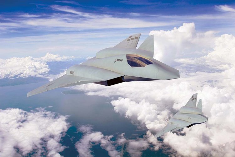
These canards got me thinking! Since there is no gap visible in these renderings, it could be that Boeing came up with a new and innovative solution. Here are my crazy thoughts...
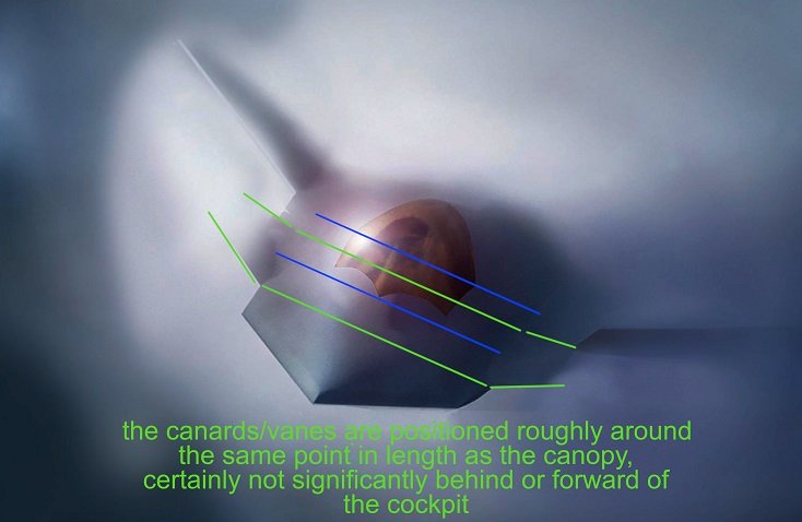
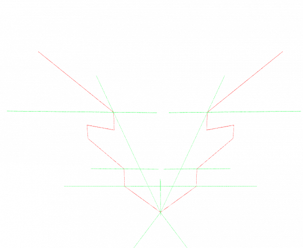
It could be possible that the axis of rotation isn't perpendicular to the longitudinal axis as usual, but collinear with the outer edge of the nose (blue).
Since the outer edge isn't parallel to the longitudinal axis, an up-and-down movement of the canard (green) would cause a change of its the angle of attack.
If so, I think the canard would be connected to the fuselage by a flexible cover. The hinge and actuator would be located inside this flexible cover (yellow). As a result, there would be no gap or seam!
View attachment 764992
Obviously such a solution wouldn't have the same freedom of movement as a conventional canard, but it would certainly be capable of changing the airflow to the wing. This would be sufficient to trim the aircraft and, in interaction with the other control effectors on the wing, could certainly contribute to pitch and roll control.


")