Various Dornier Prototypes & Projects

How much fuel volume did the 2-seater lose?

"Next in line of the Pfeil variants was the Do 335A-6 (prototype Do 335 V10), which was the night fighter variant. Armament remained unchanged from the fighter bomber, but FuG 220 Lichtenstein SN-2 or Fug 217J Neptune/FuG 218 Neptun V airborne intercept radar was to have been incorporated, the aerials being located forward of the wing (lateral beam port and vertical beam starboard). To operate the radar a second crewman was needed, and to accommodate him a cockpit was incorporated above and behind the pilot. Giving the Pfeil an even stranger appearance than before, the second cockpit also meant a considerable restructuring of the fuel system since fuel capacity was reduced to 600 litres. To augment this the weapons bay area was converted over to fuel storage. The negative effect on performance of the extra cockpit, aerials, weight and other modifications such as flame damping tubes over the exhaust ports was in the region of 10 percent, but production aircraft would have offset this partially by being fitted with DB 603E engines with MW-50 (water/methanol) boost instead of the DB 603A retained by the sole example. Production was scheduled to have been undertaken by Heinkel in Vienna, but this plan was overtaken by events and the tooling was never assembled. There was only one operational Do 335A-6, flown by Werner Baake in I./NJG 3 flying Do 335 V-10 (CP+UK) with FuG 220 Lichtenstein SN-2 radar."

Do335 A-1 fuel capacity : 1,230L (wikipedia)

I think your question is a very good one, but it would be even better if you could do your own research and post the results.
 
Last edited:
Hi! English translation of this document.

”Who knows more about this design?
There has probably never been such a late reaction to a JET & PROP topic....... (That's right!-The editor.)
While searching for other information, I came across an unknown project in issue 1/92, which was not really unraveled in the following issues.

Last year, this project came to me as one of five different three-page views of a Daimler-Benz report from 1944. The report has the somewhat longer title: "Investigation of the penetration depth of a 30 ton bomber with 5 tons bomb load at a maximum speed of 600 km/h at 7 km altitude".

The drawing of the project (below) bears the line at the bottom in Sütterlin script: "Untertürkheim, 28.1.1944, Hang" (name not certain).

In response to an inquiry from Daimler-Chrysler for further details on this topic, they regretted very kindly that they had nothing else in the archive. The illustration in JET & PROP (left) at that time is simpler than the three-sided view from the Daimler-Benz report, but there are no measurements at all.

So the drawing in JET & PROP must come from another source.
I tried to give the strange bird some shape (at the bottom).

Hans-Peter Dabrowski 30422 Hannover”
 

Attachments

  • Escanear0002.jpg
    Escanear0002.jpg
    95.4 KB · Views: 89
I understand that this drawing is from Daimler document,
"Investigation of the penetration depth of a 30 ton bomber with 5 tons bomb load at a maximum speed of 600 km/h at 7 km altitude".
Span : 11.32m?
Length : 13.76m?
 

Attachments

  • Escanear0002.jpg
    Escanear0002.jpg
    380.7 KB · Views: 94
Last edited:
For example,
Specifications (He 177 A-5/R2)
General characteristics
Crew:
6
Length: 22.00 m (72 ft 2 in)
Wingspan: 31.44 m (103 ft 2 in)
Height: 6.67 m (21 ft 11 in)
Wing area: 100 m2 (1,100 sq ft)
Airfoil: He 1.5 36.8 17.3-0.715-36.6[78]
Empty weight: 16,800 kg (37,038 lb)
Gross weight: 32,000 kg (70,548 lb)
Useful load: 15,200 kg (33,500 lb)
Powerplant: 2 × Daimler-Benz DB 610 24-cylinder liquid-cooled piston engines, 2,218 kW (2,975 hp) each
Propellers: 4-bladed VDM constant-speed propellers
Performance
Maximum speed:
488 km/h (303 mph, 263 kn) at 6,000 m (20,000 ft) in level flight
Cruise speed: 415 km/h (258 mph, 224 kn) at 6,000 m (20,000 ft)
Stall speed: 135 km/h (84 mph, 73 kn)
Range: 6,000 km (3,700 mi, 3,200 nmi)
Service ceiling: 8,000 m (26,000 ft)
Rate of climb: 3.2 m/s (630 ft/min)
Wing loading: 310 kg/m2 (63 lb/sq ft)
Power/mass: 5.25 kg/hp (11.6 lb/hp)
Armament
Guns:
** One 7.92 mm (0.312 in) MG 81 machine gun in nose.
One 20 mm (0.8 in) MG 151 cannon in forward belly gondola, and one in tail.
Two 13 mm (0.5 in) MG 131 machine gun in FDL 131Z remotely operated forward dorsal turret, and one in rear belly gondola, one in manned HDL 131/1 aft dorsal turret
Bombs: Up to 7,000 kilograms (15,000 lb) of ordnance internally, up to 2,500 kg (5,500 lb) externally on underwing racks.
 
I think that this drawing match Daimler report.
If engine is DB609 and propeller diameter is about 4m, Span is 11.32m and Length is 13.76m.
 

Attachments

  • Escanear0002.jpg
    Escanear0002.jpg
    162.2 KB · Views: 93
I'm not sure what this drawing is.
But this concept is same as the design in the Daimler's report.
Perhaps this design is for maximum speed 850km/h based on maximum speed 600km/h design.
Propeller diameter of this total 16,000hp power engine may be about 5m, because NK12 12,000 shp engine's propeller diameter is 5.6m.
This drawing clearly shows the undercarriage retract position.
What is included in the description of this drawing?
How much is propeller diameter?
If propeller diameter is 5m, each engine height is 1m.
I can't find such a engine at all.
Power unit is a big mystery.

I know that the front engine is cooled by the annular radiator in the nose, but I don't really know how the rear engine is cooled. Perhaps there is a radiator installed in the rudder.
 

Attachments

  • PP.jpg
    PP.jpg
    381.3 KB · Views: 91
Last edited:
The Do P 252 was designed as an all-metal shell construction and was intended as an all-weather destroyer, but also as a night fighter and fighter-bomber. Its attack armament could have been adapted to the respective operational tasks. It normally comprised two 30 mm MK 108s with 2 x 80 and 1 x 60 rounds in the interchangeable nose cone and two MG 213C/20s with 120 rounds each in the fuselage below the front engine. For night fighter missions, it was possible to convert to two MK 108s with 100 rounds each as a fixed inclined armament (70°). For fighter-bomber missions, a bomb load of up to 1000 kg could be carried under the outer wings. The radio and navigation equipment of the Do P 252 was very extensive in keeping with the tasks of this model and was state-of-the-art. The large cockpit with access via a ladder through the nose wheel well was initially designed for two men, but was later enlarged to accommodate three men.

The Do P 252 was equipped with either two Daimler-Benz DB 603 LA or Jumo 213 J engines, which were installed in tandem in the fuselage and drove the counter-rotating, detachable thrust screws in the rear via interlocking long-distance shafts.
In Project 1 of the Do P 252, these were still conventional VDM propellers with adjustable wooden blades and a diameter of 3.20 m.
For Projects 2 and 3, however, the Pfeil propellers were chosen, which represented a technical innovation. They came from the Heine company. The DB 603 LA and Jumo 213 J were two liquid-cooled twelve-cylinder engines with two-stage chargers and MW 50 injection. Both developed a take-off power of over 2000 hp. The exhaust rows of the two engines could be fitted with flame arresters for night-time hunting missions.

The airframe and the wing were also changed several times. Project 1 received a two-spar, all-metal wing with a laminar profile and a span of 16.40 m.
The latter was increased to 18.40 m in Project 2, and the aerodynamic area was also larger at 55 m2 due to the stronger sweep.
Project 3, on the other hand, had a slightly smaller wing with a smaller nose sweep (25°) and a span of 15.80 m. As with the Do 335, the edge of the lower vertical fin was designed as a spring-loaded emergency skid. The arrangement of the tail unit was also adopted from the Do 335.

The projects may be technologically interesting even from today's perspective, but by mid-1944 at the latest it was clear that they would not have been realized given the course of the war and the ever-worsening shortage of materials.

Aviation Classics Issue 04/2012
 

Attachments

  • P.252-1.jpg
    P.252-1.jpg
    120.1 KB · Views: 55
  • P.252-2.JPG
    P.252-2.JPG
    302.7 KB · Views: 50
  • P.252-3.jpg
    P.252-3.jpg
    508.6 KB · Views: 56
Last edited:
Another information.

The Dornier P.252 project was accepted for development as early as 1943, but was too late to be submitted to the Luftwaffe, according to their request and specification (27 January 1945) for a night fighter. Three variants were made within the project (P.252/1, /2 and /3), all of which were similar, despite slight differences in the dimensions and shapes of the wing schemes.

The P.252/3 had a long fuselage with a large cabin for three crew members. The wings were swept back at 22.5° with a dihedral "V". It was supposed to use two 12-cylinder Jumo 213J liquid-cooled engines (1,750 hp each) with a MW 50 system, which were to be installed in tandem and drive two 3.2-meter contra-rotating propellers (three-bladed propellers with 50° swept blades). Air flow was supplied to the front engine through round air intakes located in the wing roots. The second engine - through air intakes located on the sides in the rear part of the fuselage (2nd variant) or through a side air intake on the left side of the fuselage and a side air intake on the right (3rd variant). In addition, the 3rd variant had a large air intake in the rear part of the fuselage above the cruciform tail unit. The advantage of such a tail unit design was that the lower stabilizer also served as protection for the propellers from hitting the ground during takeoff.

The landing gear was supposed to be three-strut with a nose strut. The main struts retracted into the fuselage, and the front strut retracted toward the tail section.

The three crew members were in the cockpit located at the front of the fuselage, the pilot and radar operator sat back to back on the left side, while the navigator was on the right side facing the starboard side and slightly behind.

The P.252 had a powerful and varied armament (see table below), and also had an internal parabolic radar antenna under the fairing of the interchangeable nose section.

Although this design had many advantages over others, such as excellent visibility from the cockpit (due to the engines and propellers being in the tail), heavy armament and a long endurance (approximately four hours), the official Luftwaffe request called for an aircraft that would be powered by turbojet engines. Thus, the P.252 design was not accepted.​
 
Last edited:
Dornier Do P.252/3 Data w/two Jumo 213J engines
SpanLengthHeightWing
Area
Empty
Equipped Weight
Loaded
Weight*
Max. Wing
Loading
Max.
Speed
Rate of
Climb
Ceiling
15.8 m
51' 9.5"
17.2 m
56' 4.8"
5.05 m
16' 6"
50 m²
538 ft²
8600 kg
18959 lbs
12300 kg
27116 lbs
246 kg/m²
50.4 lbs/ft²
930 km/h
577 mph
21 m/sec
69 ft/sec
12500 m
41000'
* with 3400 liters (748 gallons) fuel


Attachments

  • b910e938-9344-4d44-82c5-ba2e0c8f0c64.jpg
    b910e938-9344-4d44-82c5-ba2e0c8f0c64.jpg
    67.1 KB · Views: 64
Hi! P.59.

At the outbreak of World War Two, Dornier had been working on the P.59 high-speed tandem-engine bomber, but work stopped in early 1940 to concentrate on other types, such as the Do 217 bomber.
 

Attachments

  • DORNIER P.59-05.jpg
    DORNIER P.59-05.jpg
    92.5 KB · Views: 72
Last edited:
Hi!
Source : THE ULTIMATE PISTON FIGHTERS OF THE LUFTWAFFE JUSTO MIRANDA, etc

I have not seen any supposedly official drawings of the Dornier P.252/1 fighter.
 

Attachments

  • 252.jpg
    252.jpg
    531.3 KB · Views: 55
  • P.252-1.jpg
    P.252-1.jpg
    395.5 KB · Views: 36
Last edited:
I'm not sure what this drawing is.
But this concept is same as the design in the Daimler's report.
Perhaps this design is for maximum speed 850km/h based on maximum speed 600km/h design.
Propeller diameter of this total 16,000hp power engine may be about 5m, because NK12 12,000 shp engine's propeller diameter is 5.6m.
This drawing clearly shows the undercarriage retract position.
What is included in the description of this drawing?
How much is propeller diameter?
If propeller diameter is 5m, each engine height is 1m.
I can't find such a engine at all.
Power unit is a big mystery.

I know that the front engine is cooled by the annular radiator in the nose, but I don't really know how the rear engine is cooled. Perhaps there is a radiator installed in the rudder.

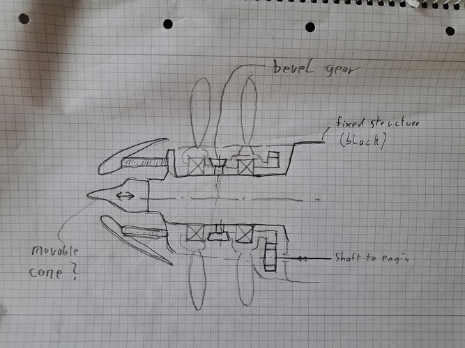
With the radial cooler in front of the propeller, no central prop shaft is possible. There must have been a fixed, central axis with relative large prop bearings going around it. This central axis must have carried the cooler, the prop bearings and quite certainly also gears between the props for the reversion of the rotation direction. Since also all fluids have to pass through it, the prop bearings must have been really large. I wouldn't be too surprised, if a cannon would have fired through the whole assembly :) ...

Although the arrangement is quite wicked, it does have the advantage that no coaxial prop drive shaft is required and might also simplify the variable pitch mechanism.

The very large prop bearings would have been quite demanding in respect to sealing and max. rpm for very large roller bearings. It was surly a quite heavy design, with some aerodynamic benefits which I don’t fully understand. Why is it beneficial to place the radiator in front of the props and not behind them?

With all the effort, I suppose the radiators of both engines could have been placed in the front.
 
I'd like to see a simplified conceptual diagram that expresses your thoughts on this nose design.
 
20241013_131444.jpg

This is a very simplified sketch of how it might have worked. I didn't include the variable pitch mechanism because this would have made it very complicate. I guess, there was a movable lever inside the fixed tube which was moved in axial direction and moved a disk back and forth through holes. The disks (guess one for each prop) could have been coaxially mounted on the outside of the tube and rollers on the prop hub could have been actuated by this, by being pushed back and forth and so actuating the variable pitch system.
 
Last edited:
View attachment 744058

This is a very simplified sketch of how it might have worked. I didn't include the variable pitch mechanism because this would have made it very complicate. I guess, there was a movable lever inside the fixed tube which was moved in axial direction and moved a disk back and forth through holes. The disks (guess one for each prop) could have been coaxially mounted on the outside of the tube and rollers on the prop hub could have been actuated by this, by being pushed back and forth and so actuating the variable pitch system.
Thanks a lot Nicknick-san!
Beautiful concept.
 

Attachments

  • 71qori07KfL._SL1500_.jpg
    71qori07KfL._SL1500_.jpg
    91.3 KB · Views: 35
Last edited:
Of course I tried to get this book, but hard to get by Amazon.co.jp.
I only find following book in Amazon.co.jp.

In any case, I think Dan-san and Justo-san's ability to gather information is amazing.

That's the one. There are two different covers - that's the regular version, the other was/is limited edition.
 
Yesterday I got this book. It is an amazing book full of original drawings. Because it is an original drawing, I have discovered something new for me, and I learn a lot. There were also many secret plans that we saw for the first time. Highly recommended.
 

Similar threads

Please donate to support the forum.

Back
Top Bottom