Mid 1963
NASA requested Boeing and Lockheed to conduct a comparative study on the four plans SCAT17, SCAT4, SCAT16, and SCAT15.
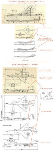
The first Image top to bottom
SCAT4
SCAT17 later became B2707-300, L2000 and NAC60
SCAT16 later became B2707-200
SCAT15 later became SCAT15F

SCAT4 was Richard Whitcomb's idea. SCAT4 was a very advanced design.
I can see following SCAT4 shapes.
(1)Six engine type
(2)Vertical and horizontal tail stabilizer with 4 engine type


Attachments

  • image.jpg
    image.jpg
    84.3 KB · Views: 215
  • Wind Tunnel Model of the NASA Supersonic SCAT 4.jpg
    Wind Tunnel Model of the NASA Supersonic SCAT 4.jpg
    112.4 KB · Views: 190
  • L-59-6216.jpg
    L-59-6216.jpg
    978.8 KB · Views: 142
  • SCAT_SST_Configuration_Model_side_view_L-60-3627.jpg
    SCAT_SST_Configuration_Model_side_view_L-60-3627.jpg
    84.2 KB · Views: 134
  • SCAT_SST_Configuration_Model2_L-62-3695.jpg
    SCAT_SST_Configuration_Model2_L-62-3695.jpg
    265 KB · Views: 145
  • scat.JPG
    scat.JPG
    65.6 KB · Views: 160
  • e57835_aecff5bd263f44938874f03833f5ab94~mv2_d_3145_2412_s_4_2.jpg
    e57835_aecff5bd263f44938874f03833f5ab94~mv2_d_3145_2412_s_4_2.jpg
    58.4 KB · Views: 148
  • Description_of_SCAT-4_Correspondence_11-8-62.pdf
    594.4 KB · Views: 28
  • SCAT4 SONIC BOOM.JPG
    SCAT4 SONIC BOOM.JPG
    51.8 KB · Views: 121
  • SCAT4 LIFT DRAG RATIO.JPG
    SCAT4 LIFT DRAG RATIO.JPG
    97.3 KB · Views: 123
Last edited:

Attachments

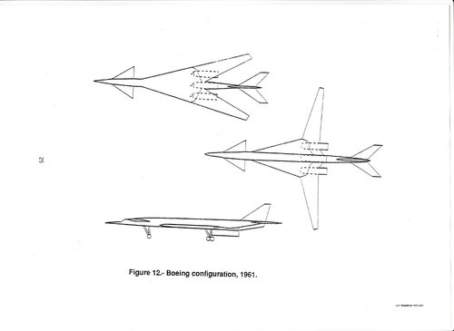
  • boeing configulation 1961.jpg
    boeing configulation 1961.jpg
    85.8 KB · Views: 129
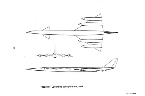
  • Lockheed configulation 1961.jpg
    Lockheed configulation 1961.jpg
    80 KB · Views: 127
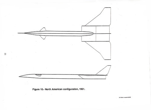
  • North American configulation 1961.jpg
    North American configulation 1961.jpg
    65.6 KB · Views: 121
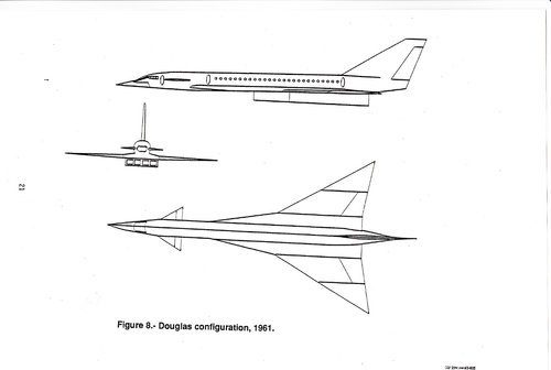
  • Douglas configulation 1961.jpg
    Douglas configulation 1961.jpg
    90 KB · Views: 113
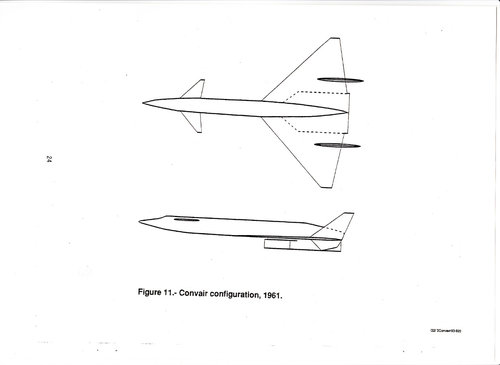
  • Convair configulation 1961.jpg
    Convair configulation 1961.jpg
    71 KB · Views: 119
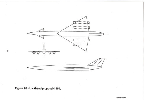
  • Lockheed proposal 1964.jpg
    Lockheed proposal 1964.jpg
    78.3 KB · Views: 119
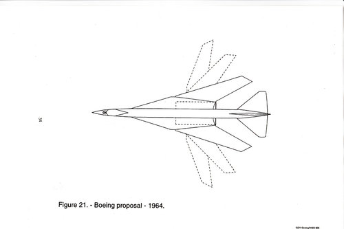
  • Boeing proposal 1964.jpg
    Boeing proposal 1964.jpg
    70.6 KB · Views: 146
Last edited:
Hi!
NAA company showing their 1963-64 proposals.
And NAC2000 SST.


Attachments

  • 63-64-ssts.jpg
    63-64-ssts.jpg
    426.7 KB · Views: 152
  • 367c9e20b539e585110e477b55c7b030.jpg
    367c9e20b539e585110e477b55c7b030.jpg
    27.7 KB · Views: 140
  • NAC2000.JPG
    NAC2000.JPG
    60.4 KB · Views: 138
Last edited:
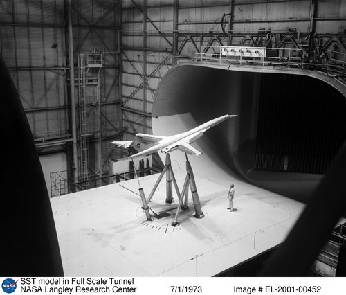
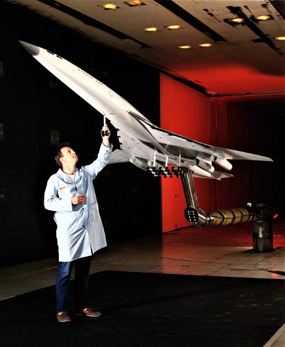
Here is an interesting 1974 NASA report on testing a T-Tailed 733-290 like configuration, which I find even nicer than the 733-290. I believe it’s the same model as this one :

SST_model_in_Wind_Tunnel.jpg

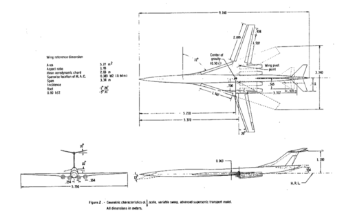
here is the model scale plan extracted from the report:

t-tailled-733-290.png

As noted by Skybolt before in post #224, T-tail was tested for the 733 before, being rejected because of deep-stall problem, But this was re-investigated later after the end of SST program to see if CCV would solve the problem , here an interesting extract:

The present study is part of an overall effort by the NASA to provide the technology base for the development of advanced supersonic vehicles. The configuration concept which is the subject of this paper is a derivative of one studied in the National SST (supersonic transport) program (references 1 and 2) and traces its ancestry to the SCAT 16 configuration of the SCAT
(supersonic commercial air transport) studies (reference 3). As studied in the SST program, the concept exhibited one of the highest ratios of payload to gross weight of all those submitted for evaluation.
The dominant feature of the configuration is its non-integrated, variable-sweep wing. The variable-sweep feature was utilized to provide high
levels of low-speed lift, good subsonic flight efficiency, and good supersonic
cruise efficiency with a relatively small, highly loaded wing which would
involve less structural design uncertainty than would the lightly loaded, large wings of competing concepts.
The primary reason for abandoning the non-integrated, variable-sweep concept during its development was a conflict between longitudinal stability
criteria of that time, and effects of the engine exhaust on the horizontal tail. Placement of the horizontal tail in a high, or T-tail, position would have eliminated adverse thermal and acoustic effects of the jet on the tail and would have prevented a venturi-like suck-down of the horizontal tail as the exhaust jet streamed between it and the ground during takeoff rotation, both of which were problems for a low-tail configuration.
However, a T-tail was generally known to produce a deep-stall problem as the tail dropped into the wake of the stalled wing and became ineffective. Because "stick pusher"
or attitude-limiting systems, which are dependent upon attitude and pitch- rate sensing, were not then considered permissible in commercial aircraft, the contractor conducting the SST study ultimately took the alternate route of integrating the wing and horizontal tail, and suspending the engine nacelles from the latter, before abandoning the variable-sweep approach altogether. Since that time, developments in stability criteria and in aero- electronic technology and an increased emphasis on CCV (control-configured vehicles) have opened the path to serious study of a T-tail solution of the problems of the variable-sweep SST.
 
Last edited:
Oh super!! Thanks a lot.
This tail shape was same as B727, but engine lcation is diffenent.

press この動画はyoutubeでご覧下さい。

 
Last edited:

Attachments

  • image21.jpg
    image21.jpg
    44.2 KB · Views: 146
  • SSTswingwing.jpg
    SSTswingwing.jpg
    12.8 KB · Views: 125
  • 733-290 model.jpg
    733-290 model.jpg
    439.5 KB · Views: 117
  • BI229975.jpg
    BI229975.jpg
    82.2 KB · Views: 129
Last edited:
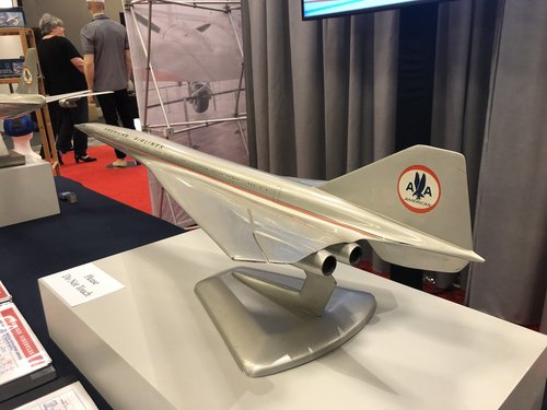
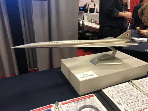
"[B]Chris Sloan[/B]‏ @[B]airchive[/B] Original Boeing 2707 SST model in the 1964-68 AstroJet livery on display at the American Airlines Annual Leadership Conference Expo courtesy of the C.R. Smith Museum."

D0VdjMPWkAAhUkr.jpg D0VdjMPXgAIuFjq.jpg

Btw, I (we :) ) keep posting stuff in this monster thread, but if modos find it inapropriate i'll stop. For sure the thread is a wealth of infos on the SST, excellent reference, but it's also getting difficult to follow due to size and images posted 2 or even 3 times in the thread (my bad too...).
 
galgot-san!
How about Douglas 2229 official models?
There are three models, each models have little different shape?


Attachments

  • high speed condition nose.jpg
    high speed condition nose.jpg
    209.1 KB · Views: 119
  • low speed condition nose.jpg
    low speed condition nose.jpg
    207.8 KB · Views: 123
Last edited:
I think its the same design. Only , one model shows it in cruise supersonic configuration ( wing tips moved down like XB-70, and windshield in up position), while the others are in lower speed configuration.
 
Left side model's cockpit upper fuselage is rounded and canard seems to be small. And fuselage each side windows are 71 where other two windows are 84/85.
Left side model is short. It's a long range version same as L2000-7A?
 

Attachments

  • three models.jpg
    three models.jpg
    461.6 KB · Views: 130
  • 19613.jpg
    19613.jpg
    159.7 KB · Views: 127
  • short fuselage version low speed mode.jpg
    short fuselage version low speed mode.jpg
    199.6 KB · Views: 113
  • long fuselage version low speed mode.jpg
    long fuselage version low speed mode.jpg
    838.1 KB · Views: 105
  • long fuselage version high speed mode.jpg
    long fuselage version high speed mode.jpg
    282.3 KB · Views: 108
Last edited:
Left side model's cockpit upper fuselage is rounded and canard seems to be small. And fuselage each side windows are 71 where other two windows are 84/85.
Left side model is short. It's a long range version same as L2000-7A?
Ah yes ! didn't noticed that. Would be nice to know what is writen of the coper plates on the stands... if they have something different from each other.
EDIT : seems its all writen "Douglas SST" ...

Btw, never really checked Douglas 2229 history. Wikipedia page is quite detailled :
"...After studying the design, Douglas concluded that the SST would not work economically, and declined to enter the Model 2229 in the National Supersonic Transport (NST) program in 1963."
Wise guys :)...
 
Last edited:

Attachments

  • SCAT-4.JPG
    SCAT-4.JPG
    53.6 KB · Views: 112
  • SCAT-15.JPG
    SCAT-15.JPG
    47.5 KB · Views: 103
  • SCAT-16.JPG
    SCAT-16.JPG
    52 KB · Views: 113
  • WING EXTENDED SCAT-16.JPG
    WING EXTENDED SCAT-16.JPG
    50.3 KB · Views: 121
  • SCAT-16 test model.png
    SCAT-16 test model.png
    1.8 MB · Views: 167
Last edited:
Btw, never really checked Douglas 2229 history. Wikipedia page is quite detailled :
"...After studying the design, Douglas concluded that the SST would not work economically, and declined to enter the Model 2229 in the National Supersonic Transport (NST) program in 1963."
Wise guys :)...
[/QUOTE]
R.E.G Davies, who worked in marketing at Douglas, based a book on why SSTs would never make sense.
 
Last edited:
A renowned Japanese scholar said: “Stupid people and engineers want to make fast and big things.”:D


Engineers are really hard work.
First he needs to have enough talent.
If he doesn't show his originality, he can't satisfy his customers.
His proposal is the best of all proposals and must be feasible.
Careful attention is required so as not to make mistakes.
He must study every day to get the latest information.
His work is really sober(Planning, Calculation, Development, Integration, Simulation, trade off study and make Fabrication/testing sequence), and he has to work hard until late at night.
Sometimes he has to sacrifice his weekend fun.
If something happens, he first thinks it is his responsibility.
 
Last edited:
Hi! Convair study.
Sorry I miss the source.:confused:
 

Attachments

  • CONVAIR SST STUDY.jpg
    CONVAIR SST STUDY.jpg
    219.1 KB · Views: 144
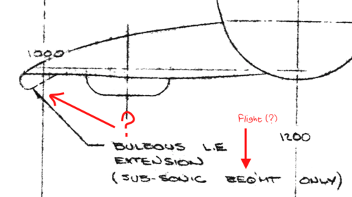
I’m looking for infos about the wing fixed part leading edge of model 733-197.
On the plan sold at:
One can see this :
197LE.png
and also on this image :
197wing.png
from this document:

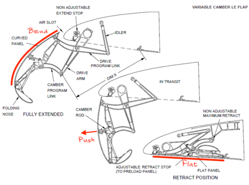
My question is , how can the leading edge go from sharp edge to "bulbous".
I don’t understand how the section can go from sharp to round…
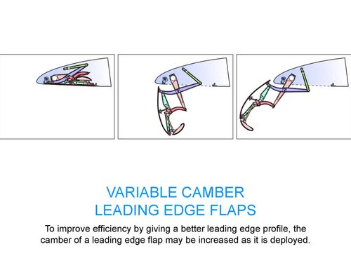
Only found this illustration of something a bit similar (changing the LE section) , some complicated Krueger flaps ?
slide-13.jpg
I don’t even understand exactly how these work, as the skin lay flat when closed, then its curved when opened…
Could it be this kind of thing on the 733-197 wing ?

Edit:
Ok, the example above show 747 Krueger flaps, here better image :
710x528_14060637_8167925_1461357208.jpg.gif
Patent here :
Still, don't think it would work on the -197 drawing, as it would have to bend the surface much more.
Plus it looks completely closed on the underside on the -197 drawing.
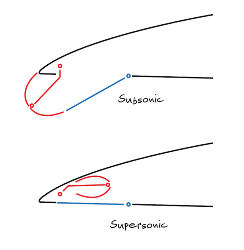
So maybe something like that :
733-197KruegerflapsMaybe.png
 
Last edited:
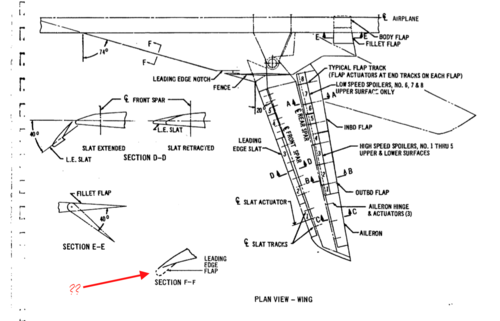
Look at section f-f (LERX) and think at the sweep angle of blended section. The extended part is just hidden inside the outer shape and deployed to increase alpha tolerence before flow separation.

On the mig, the flap is rotated from a tangent recessed position. Nothing prevent you to carve a volume on the underside to have that flap tip bulbous.

1401420d1439065807t-mig-29-fulcrum-balance-rests-us-mig29m_enlarged_flaps.jpg
 
Last edited:
While googling , the search engine presented me a small image preview included in this document :
25 $ to download ! :(

anyway here is the small image :
IMG_4042.PNG
Think is 733-636. Funny, I thought all arrow wings models would be numbered 969-xxx.
Looks like a -300 with delta wing swapped to a arrow wing.
 
Fast airplanes also have to fly well at low speeds to take off and land. Here, a technician is installing the nose landing gear on a proposed High-Speed Civil Transport model to prepare it for high-angle-of-attack tests in the 14- by 22-Foot Tunnel. The test section walls were in their closed position for these tests.
sst.jpg
 
Fast airplanes also have to fly well at low speeds to take off and land. Here, a technician is installing the nose landing gear on a proposed High-Speed Civil Transport model to prepare it for high-angle-of-attack tests in the 14- by 22-Foot Tunnel. The test section walls were in their closed position for these tests.

Aie !! My hears ! No shouting please ... :)

This one is from after 1971, not sure if it's Boeing or MDD.
 
Hi!

Wing is very large. Perfectly different dimension.
 

Attachments

  • SST farewell.jpg
    SST farewell.jpg
    131.1 KB · Views: 204
Hi!
I compare Boeing B2707-300 prototype and operational.
Operational model is about 3.5m longer than prototype model.Wing front view slightly changed. Horizontal tail stabilizer moved higher position.
Outboard aileron area enlarged.
Operatinal model fuselage shape looks like L2000-7B.
Prototype model range : 3575nm, Operational model range : 3530nm

Source : Aireview magazine and...
 

Attachments

  • Boeing 2707-300.jpg
    Boeing 2707-300.jpg
    619 KB · Views: 169
  • B2707.docx
    320.9 KB · Views: 30
  • boeing_2707-300_prototype.gif
    boeing_2707-300_prototype.gif
    149 KB · Views: 156
  • boeing_2707-300_operational.gif
    boeing_2707-300_operational.gif
    154.8 KB · Views: 145
Last edited:
Hi Blackkite San,
Sorry , i think this one shows the -300 as intented as in late 1968 / early 1969, not specifically the prototype.
See configurations released by Boeing to the press at the period, and published with the very detailled cutaway plan in several magazines at these times, namely Interavia, AviationMagazine,
Flight International and Japanese AirReview (i think...).
Then in Late 1969 another configuration is released, with a new tailplane geometry. One short 280 ft production model, then a 286 ft prototype and a 298 ft Production model.
See the following montage, I love SST ornithology :
-300 evolution.jpg
 
Last edited:
Ummm..........very difficult.;)
Horizontal tail stabilizer shape!!
Boeing planned domestic version and intercontinental version same as Lockheed L2000-7A and 7B?(Same as Douglas 2229?)
 
Last edited:
Ummm..........very difficult.;)
Horizontal tail stabilizer shape!!
Boeing planned domestic version and intercontinental version same as Lockheed L2000-7A and 7B?(Same as Douglas 2229?)

I don't know for the 2707-300, but back on the 733-290 yes, I saw two versions intended mentioned on the same Boeing 733-290 presentation.
One domestic and one intercontinental. Same dimensions but different weight (fuel and pax capacity I suppose).
Sorry don't have the numbers, documents are not mines.

Edit : got the infos , here you go,
planned was 733-290 "Intercontinental" with
230 pax
500000 lbs Max ramp weight
219900 lbs operating empty weight
320000 lbs Max Ldg weight
264180 lbs Fuel capacity
16-40" main gear tires size

And 733-291 "transcontinental" (domestic) with
209 pax
425000 lbs Max ramp weight
205900 lbs operating empty weight
302000 lbs Max Ldg weight
204100 lbs Fuel capacity
16-38" main gear tires size

Both same external dimensions/shape and same GE4 engines.
 
Last edited:
Hi! Boeing 733-290 larger image and 3D model.

I have never seen 733-390 large drawing.
 

Attachments

  • 733-290 PICTURE.jpg
    733-290 PICTURE.jpg
    391.7 KB · Views: 216
Last edited:
From Ailes 13/6/1961,

the Northrop SST.
 

Attachments

  • Les_Ailes___journal_hebdomadaire_[...]_bpt6k3201019g_3.jpeg
    Les_Ailes___journal_hebdomadaire_[...]_bpt6k3201019g_3.jpeg
    1.7 MB · Views: 223
Hi! Boeing 733-290 larger image and 3D model.

I have never seen 733-390 large drawing.

thanks, I didn't had that 733-290 image at that size :)

The 3d model is not correct, I wouldn't put 10 $ for it. For the -290 the nose wasn't suppose to drop like that and MLG is not like that. Also very simplified wing and all.
 
This drawing shows Boeing 2707-200.(Please confirm drawing title.)
Single cranked nose and canard.
 

Attachments

  • 65A10476.jpg
    65A10476.jpg
    809.9 KB · Views: 189
  • 2707-200.jpg
    2707-200.jpg
    240.9 KB · Views: 179
Last edited:

Similar threads

Please donate to support the forum.

Back
Top Bottom