You are using an out of date browser. It may not display this or other websites correctly.
You should upgrade or use an alternative browser.
You should upgrade or use an alternative browser.
US Lifting Bodies Studies - START (ASSET/PRIME), FDL, X-24, etc.
- Thread starter Archibald
- Start date
airrocket
Dreams To Reality
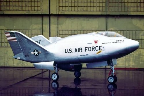
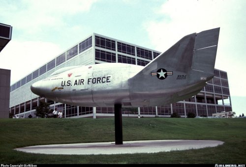
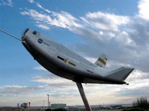
Any pics of the SV-5J turbine powered X-24A? I wonder where the jets where mounted. What pics I have seen are of the SV-5J that was converted back to rocket power for display at WRP Ohio.
XP67_Moonbat
ACCESS: Top Secret
- Joined
- 16 January 2008
- Messages
- 2,271
- Reaction score
- 543
- Joined
- 1 November 2009
- Messages
- 638
- Reaction score
- 428
airrocket said:Any pics of the SV-5J turbine powered X-24A? I wonder where the jets where mounted. What pics I have seen are of the SV-5J that was converted back to rocket power for display at WRP Ohio.
The single engine would have been in the same location as the rocket engine on the X-24A. The picture posted by XP-67 Moonbat shows the intake location and type on the first of the SP-5J aircraft. Photos in Jay Miller's (Jay Miller so I can't post them here) The X-Planes X-1 to X-29 (and . . . X-1 to X-31) show both the first and the second aircraft. One of those photos shows the vehicle from the back with an empty engine bay.
The caption on one of the photos says that the second SP-5J was missing the intake. I'm not so sure that it was missing. I vaguely remember seeing a drawing back in the 70s showing an SP-5J with a NACA style intake on the bottom. Does anyone else remember seeing that?"
- Joined
- 29 July 2009
- Messages
- 1,768
- Reaction score
- 2,469
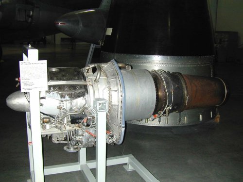
The SV-5J was to have flown with the J60-PW-1 (prototype designation) jet engine, which later becomes the JT12A. Martin was encouraged to develop the SV-5J concept after Chuck Yeager, head of the Aerospace Research Pilots School (to train USAF astronauts), suggested that he could use such an aircraft to help train his future military-men-in-space. Martin developed two 'shells' of the SV-5J and approached Milt Thompson to flight test it. Engineers were concerned about the stability of the vehicle during its powered climb to altitude.
Attachments
airrocket
Dreams To Reality
looking at moonbat pic I gather that dark object underneath between the wing wheels is the funnel like shape intake?
- Joined
- 1 November 2009
- Messages
- 638
- Reaction score
- 428
Yes, that is the intake on the underside of that one.
Retrofit
ACCESS: Top Secret
- Joined
- 21 February 2007
- Messages
- 656
- Reaction score
- 337
Hi,
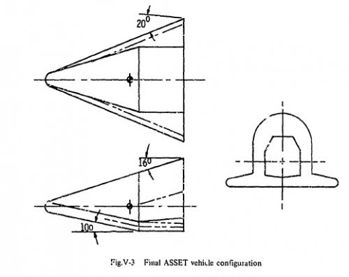
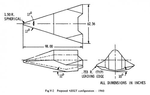
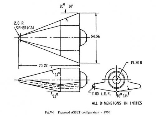
3 (V1, V2 & V3) ASSET configuration proposals. The last V3 one was selected.
Sources: AGARD Lecture serie 42 volume 1: "Aerodynamic problems of hypersonic vehicles", pages 151-152/238.
AD number: AD0747878
http://www.dtic.mil/srch/search?template=%2Fdtic%2Fsearch%2Fresults-template.html&changequery=1&hl=y&s=1&searchview=d4&enableLemmatization=yes&site=dticst&q=AD747878&s=1&c=t3&submit.x=12&submit.y=11.
Is there a 3V drawing of the MARTIN X-24C' proposal available (All the X-24C' 3V in this thread seem to be related to the LOCKHEED proposals)?
Note: Perspective drawing and:
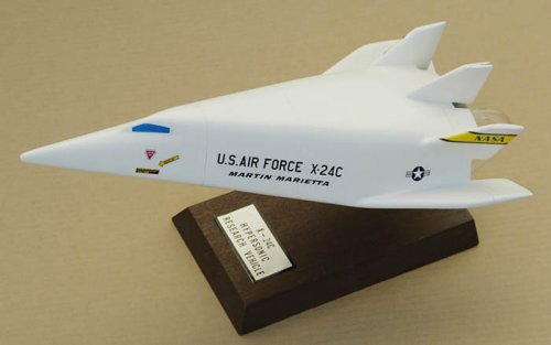
Thanks in advanceoverscan said:Martin X-24C desktop model from beautiful Chad Slattery site http://home.earthlink.net/~chadslattery/
© 2008 Chad Slattery
Attachments
- Joined
- 1 April 2006
- Messages
- 11,375
- Reaction score
- 10,209
Retrofit said:Sources: AGARD Lecture serie 42 volume 1: "Aerodynamic problems of hypersonic vehicles", pages 151-152/238.
AD number: AD0747878
http://www.dtic.mil/srch/search?template=%2Fdtic%2Fsearch%2Fresults-template.html&changequery=1&hl=y&s=1&searchview=d4&enableLemmatization=yes&site=dticst&q=AD747878&s=1&c=t3&submit.x=12&submit.y=11.
It's me only who recieves
"No full text document exists for this AD Number.
Content-type: text/html ERROR: Can't write to the log file."
message at DTIC site trying to access full-text pdfs recently?
[/quote]
Desert Dawn
ACCESS: Confidential
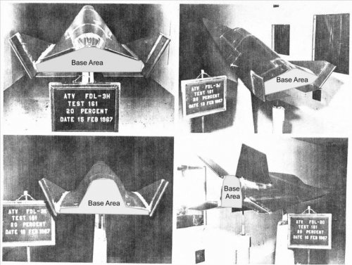
Dynoman said:May have been posted earlier, but I couldn't find it in the search. Here are FDL-3H, FDL-3J, FDL-3K, and I think FDL-3O(?).
FDL-2, bottom right corner. Posted earlier by someone else.
nivek626
ACCESS: Restricted
- Joined
- 12 June 2008
- Messages
- 27
- Reaction score
- 42
I am sure some of you have already found this but there is some great info on the early X-24C at the NTRS but beware it is a large file 15.07 MEG. IT includes some good info on landing gear ,rocket motors, construction and such. enjoy http://ntrs.nasa.gov/archive/nasa/casi.ntrs.nasa.gov/19790007768_1979007768.pdf
nivek626 said:I am sure some of you have already found this but there is some great info on the early X-24C at the NTRS but beware it is a large file 15.07 MEG. IT includes some good info on landing gear ,rocket motors, construction and such. enjoy http://ntrs.nasa.gov/archive/nasa/casi.ntrs.nasa.gov/19790007768_1979007768.pdf
If anyone is interested ina color schlieren photro see:
http://lisar.larc.nasa.gov/UTILS/info.cgi?id=EL-2001-00415
I was a flight test engineer for McDonnell, assigned to Edwards Air Force Base from late 1966 to mid 1968. One of several memories of other test activities at that time was watching an unpowered lifting body test flight, probably the HL-10. The drop was made directly over the Edwards Lake Bed at an altitude of 45,000 feet, about eight miles above the lake bed. You could see the B-52 and contrails from three chase F-104s flying roughly north in formation to the drop point. When the formation was adjacent to and a bit east of the touchdown point, there was suddenly another contrail going ballistic, with the chase planes pushing over to follow it. They all came out of contrail altitude pretty quickly and were difficult to see with the naked eye, so we shifted our gaze to the west, above the hills. After about three minutes, the lifting body and the chase planes came into sight, sinking fast, probably coming through 10,000 feet, having made a U-turn following the drop for a landing on lake bed runway 18, which was about 23,000 feet long. The 104s had their gear down, with one on each side of the lifting body and fairly close and the third somewhat farther out. The pilot would flare, the gear would pop out, and it would touch down at something on the order of 200 knots. The 104s would not touch down but would go into burner, clean up, and climb out while the lifting body was careening across the lake bed trailing dust for quite some distance. (Imagine an elongated, upside-down, Volkswagen Beetle, going like stink.) Total flight time was about four minutes from 45,000 feet, which given the altitude of Edwards, was an average rate of descent of a bit over 10,000 feet per minute, or a little over 200 knots straight down. My impression was that the "glide" angle was about 30 degrees but it may not have been that steep. It was quite a sight.
An interesting summary of the HL-10 program: http://dtrs.dfrc.nasa.gov/archive/00000234/01/RP1332.pdf
An interesting summary of the HL-10 program: http://dtrs.dfrc.nasa.gov/archive/00000234/01/RP1332.pdf
- Joined
- 13 August 2007
- Messages
- 8,434
- Reaction score
- 10,951
I found some nice Photo's of US Lifting Bodies
http://crgis.ndc.nasa.gov/historic/Additional_Photos_for_12-Foot_Low_Speed_Tunnel#HL-10_and_HL-11
http://crgis.ndc.nasa.gov/historic/Additional_Photos_for_12-Foot_Low_Speed_Tunnel#HL-10_and_HL-11
- Joined
- 27 December 2005
- Messages
- 17,746
- Reaction score
- 26,362
nivek626 said:I am sure some of you have already found this but there is some great info on the early X-24C at the NTRS but beware it is a large file 15.07 MEG. IT includes some good info on landing gear ,rocket motors, construction and such. enjoy http://ntrs.nasa.gov/archive/nasa/casi.ntrs.nasa.gov/19790007768_1979007768.pdf
Nice... missed this.
CONFIGURATION DEVELOPMENT STUDY OF THE X-24C HYPERSONIC RESEARCH AIRPLANE - PHASE I [Lockheed]
Four hypersonic research airplane configurations found to be the most cost effective were selected for further refinement. The selection was based on a systematic analysis and evaluation of realistic designs, involving nine different configurations, evolving from three different structural/thermal concepts, coupled with existing rocket and sustainer engines. All configurations were constrained by the mission profiles, research requirements, aerodynamic envelope and maximum launch weight established by NASA.
http://ntrs.nasa.gov/archive/nasa/casi.ntrs.nasa.gov/19790007768_1979007768.pdf
CONFIGURATION DEVELOPMENT STUDY OF THE X-24C HYPERSONIC RESEARCH AIRPLANE - PHASE II [Lockheed]
http://ntrs.nasa.gov/archive/nasa/casi.ntrs.nasa.gov/19790008668_1979008668.pdfThe X-24C Hypersonic Research Vehicle, configured with a heat-sink structure, a launch mass limit of 31.75 Mg and powered by an LR-105 Rocket Engine plus 12 LR-101 Sustainer Engines, was found to be the more cost effective of the candidate configurations. In addition, the configuration provides the maximum off design growth potential capability and subsequently, was selected as the candidate configuration to be subjected to the design refinement study in the remaining segment of the study. Selection of this configuration was based on the analytical study conducted on the performance growth capabilities of the candidate configurations selected from the Phase 1 Study.
CONFIGURATION DEVELOPMENT STUDY OF THE X-24C HYPERSONIC RESEARCH AIRPLANE - PHASE III [Lockheed]
http://ntrs.nasa.gov/archive/nasa/casi.ntrs.nasa.gov/19790008669_1979008669.pdfThe conclusion evolved from the three phased study on the configuration development of the X-24C Hypersonic Research Airplane makes it evident that it is practical to design and build the high performance National Hypersonic Flight Research Facility airplane with today's state of the art within the cost and operational constraints established by NASA. The vehicle launched at 31.75 Mg from the B-52 can cruise for 40 seconds at Mach 6.78 on scramjets. Without scramjets it can approach Mach 8 with a 453.6 Kg payload or do 70 seconds of cruise at Mach 6 with a 2.27 Mg payload. Reduction in cost is possible with a vehicle scaled to a lesser mass and capability.
airrocket
Dreams To Reality
Amazing after all those flights ending with X-24B which demonstrated sharper nose flat bottom planform was far superior to the blunt bodies with vertical winglets. FDL-7 planform series incorporated these design attributes. So what does NASA and mainstream aerospace do? They ignore all that and to this day NASA is still generating blunt designs? Did a generation of engineers forget the lessons of the past?
- Joined
- 26 September 2008
- Messages
- 1,960
- Reaction score
- 746
airrocket said:Amazing after all those flights ending with X-24B which demonstrated sharper nose flat bottom planform was far superior to the blunt bodies with vertical winglets. FDL-7 planform series incorporated these design attributes. So what does NASA and mainstream aerospace do? They ignore all that and to this day NASA is still generating blunt designs? Did a generation of engineers forget the lessons of the past?
Is that a rhetorical question or are you assuming that they're all idiots?
- Joined
- 25 June 2009
- Messages
- 14,749
- Reaction score
- 6,114
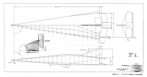
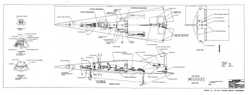
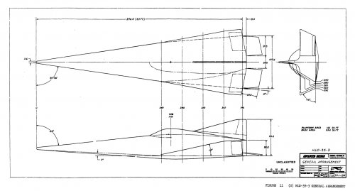
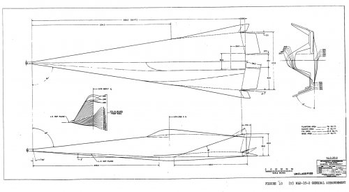
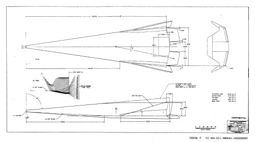
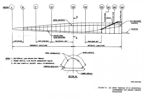
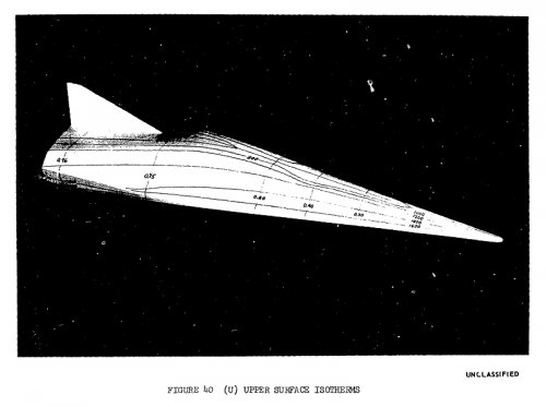
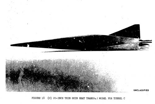
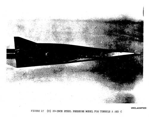
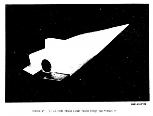
Conceptual design and experimental wind tunnel testing of unmanned entry research vehicles having high hypersonic lift/drag ration and high volume are desribed. Analytic parametic data are presented for two lifting body classes designated HLD-35 and FDL-5. The FDL-5 is a unique configuration which is aerodynamically stabilized without outboard fins. Experimental aerodynamic and heat transfer data from the Arnold Engineering Development Center Wind Tunnels A, B, C and F are compared with analytic data for the FDL-5. Candidate structure and subsystems are selected for performing unmanned hypersonic research with the vehicle.
Source:
Couldn't find these great projects by name with the search engine... Sorry in advance if I'm duplicating anything!
Attachments
- Joined
- 25 June 2009
- Messages
- 14,749
- Reaction score
- 6,114
Steve Pace
Aviation History Writer
- Joined
- 6 January 2013
- Messages
- 2,266
- Reaction score
- 225
Sure does remind me of Lockheed's unbuilt X-24C configuration. -SP
FutureSpaceTourist
ACCESS: Top Secret
- Joined
- 10 March 2010
- Messages
- 590
- Reaction score
- 34
XB-70 Guy said:Sure does remind me of Lockheed's unbuilt X-24C configuration. -SP
If I've got my facts straight the FDL-5 doc referenced below (from 1968) pre-dates work on Lockheed's L-301 (intended to be the X-24C), or maybe they were concurrent? I guess there was some re-use between the two!
Desert Dawn
ACCESS: Confidential
Hi Stargazer, they are all in the FDL-5 / X-24 C, thread.
airrocket
Dreams To Reality
I have FDL-5 info files are way to large to post here.
- Joined
- 21 April 2009
- Messages
- 13,745
- Reaction score
- 7,666
Fifty year old article on space planes from the Air Force Association:
The Spaceplane—Toward a Space-Age Kitty Hawk
By J. S. Butz, Jr.
Technical Editor
A sizable number of aeronautical experts in industry, government research agencies, and the Air Force believe they can achieve the marriage of airplane and space vehicle in the decade ahead. The result would be a gigantic step forward. If, as Air Force planners logically contend, the atmosphere and space are a single operating continuum called aerospace, the inexorable pressure of operational requirements on technology must eventually marry the airplane to the space vehicle. The object of the wedding is to conceive a winged offspring which can fly into orbit, rather than being shot there with large rocket boosters, and which can take off from and land on conventional airfields. The first successful flight of such a vehicle, into orbit and return, will truly mark the Kitty Hawk milestone of man's conquest of space.
The "Spaceplane" concept has an awesome set of general requirements. It is envisioned as a self-contained, one-stage vehicle which uses air-breathing engines to maneuver in the atmosphere and to accelerate itself to satellite speed of about 18,000 mph. It must either carry enough fuel into orbit to maneuver extensively in space or be able to collect this fuel as it orbits in the upper atmosphere. Finally, the Space-plane must be able to withstand the heat of reentry, maneuver at very high speeds in the atmosphere as it returns to the earth's surface, and land under power at relatively low speeds at any desired airfield.
Militarily, the attractiveness of Spaceplane is unquestionable. However, the first glance from the technical viewpoint indicates defiance of many of the physical laws which govern the design of aircraft, air-breathing engines, booster rockets, and reentry vehicles. It certainly pushes current technology to its limits, and in many areas the concept cannot be proved or disproved until more research is completed. As with all vehicles which strain existing knowledge, Spaceplane has both strong proponents and strong critics. The argument is primarily over where Space-plane fits into the time schedule. Few people contend that Spaceplane could never be built, but many question whether it could fly in the next ten years, even if it were given the highest national priority in a crash development program.
These critics point to the host of separate vehicles now under development, which considered in the aggregate could accomplish all of the missions Space-plane can and perhaps better. An example is the fact that large boosters such as Nova can put more weight into orbit in much less time. The reconnaissance and early-warning satellites, such as Samos and Midas, can accomplish these missions as well and perhaps as cheaply as Spaceplane. It is also probable that the Spaceplane, which will need a very large volume to carry its load of hydrogen fuel, will never be able to maneuver as well during reentry as a heavier-for-its-size Dyna-Soar-type hypersonic glider.
In effect, it is the multipurpose aircraft requirement carried over into the space field. It is very difficult to say whether it is better to have a group of high-performance specialized vehicles or a multipurpose vehicle which can do many of the necessary jobs but none of them at top performance. But the increasing cost and complexity of individual weapon systems make the multipurpose approach an attractive one. The Spaceplane proponents do not suggest that the current space programs be canceled and that all effort be put on the all-purpose vehicle. They do believe emphatically that a single-stage vehicle capable of aircraft-type takeoffs and landings, which can carry men and a sizable payload in between the atmosphere and space almost at will, will be the foundation of the space-vehicle program during the 1970s.
The best indication available today that the Space-plane is feasible and can be flown before 1970 is that a sizable group of aeronautical experts sprinkled through industry, government research agencies, and the Air Force not only believe that it can be done but are enthusiastic about it. Several manufacturers have already submitted preliminary type Spaceplane proposals to the USAF. These have been evaluated and considered in the light of proposals from government laboratories and from within the Air Force. The USAF budget for fiscal 1962 contains money for more detailed Space-plane studies and for state-of-the-art experiments.
Not even the enthusiasts, however, claim that Space-plane will be an easy technical development. Much of the current US research and development effort, such as Dyna-Soar, the X-15, and state-of-the-art work in high-temperature structures, high-speed stability and control, etc., will feed valuable information into the Spaceplane project. But one field of experimental research vital to the project has been virtually abandoned in recent years, and there can be no sensible hope for a true one-stage Spaceplane unless large-scale research in this area is revived. The missing technical link in the Spaceplane concept is the air-breathing engines that can operate at hypersonic speeds. Air-breathing propulsion systems theoretically can eliminate the need for high-thrust rocket boosters by drawing their oxidizer supply from the atmosphere. Since the weight of oxygen needed is much larger than the fuel weight, hypersonic air-breathers offer the hope of very light, orbital propulsion systems.
The key to hypersonic air-breathing engines is the ability to burn the fuel externally. In effect, the engines must be turned inside out so that their hot parts will be exposed and can be cooled by radiation. The air entering a conventional enclosed engine at hypersonic speeds would be literally too hot for the engine component to handle. And there would be no way to further raise temperature and therefore produce thrust by adding "fuel to the flame." External burning has been studied theoretically for many years, but the only extensive experimental research effort was conducted at the Lewis Laboratory of the National Advisory Committee for Aeronautics in the middle 1950s. This research proved conclusively that external burning would work at relatively low Mach numbers. It also cleared up enough theoretical unknowns to convince many thermodynamicists and engine designers that it would work through the high Mach number range right on up to orbital speeds and at very high altitudes.
The external-burning effort was not continued, however, and it was abandoned along with all other air-breathing engine research when the NACA became the National Aeronautics and Space Administration. The decision to drop all other air-breathing work was perhaps the most controversial one yet made by NASA. It raised strong protests from within industry, the military, European aeronautical circles, and within NASA itself. It forced the professional reorientation of the research scientists at Lewis Laboratory who had achieved worldwide eminence for their efforts with air-breathing engines. The decision not only weakened any Spaceplane or air-breathing booster development but limited hypersonic aircraft configurations to the essentially one-shot, rocket-powered, boost-glide type.
During the past couple of years theoretical work with external burning has continued, primarily in industry. Further experimentation is needed immediately, however, to obtain detailed design data and to bring the Spaceplane onto more solid ground technically. The development problems of a Spaceplane extend far beyond external burning, and they occur in three of its basic modes of operation, which are flight into orbit, maneuvering in space, and reentry into the atmosphere. When the Spaceplane takes off in the conventional manner and accelerates to a speed of around 18, mph while climbing to an altitude of 200 miles or more, its flight will resemble much that of a large rocket as of an airplane. An analysis of this flight into orbit must be made from the standpoint of both types of vehicles.
Fundamentally, the rocket vehicle is much easier to analyze than the hypersonic airplane. There are two basic factors which influence the ability of the ICBM-type rocket or a large space booster to accelerate to orbital speed, and they are just as important to the Spaceplane as they are to the rocket. These factors are the vehicle's mass ratio and the specific impulse of its propellants. The mass ratio is the total takeoff weight of the vehicle divided by its weight after all fuel has been consumed and the engines stop. Mass ratio is an indication of the lightness and efficiency of the vehicle's structure, and it is a dimensionless number. The specific impulse is a measure of the energy released by each pound of propellant. Its definition is the pounds of thrust produced by each pound of propellant burned each second, so that the specific impulse is given in seconds for each propellant combination of fuel and oxidizer.
In terms of practical numbers the propellants currently used in operational rocket boosters have specific impulse ratings of around 250 seconds or a little more This means that a single-stage rocket would have t have a mass ratio of around fifteen to achieve orbit speed if it carried very little payload. Adding a large payload—so that something useful can be done with the rocket after it is in orbit—means that the mass ratio would have to be increased significantly. Unfortunately, the best mass ratio that can be achieved with any large single-stage vehicle today, using the construction materials which are available, is only about seven or eight. So it is not possible to use single-stage boosters to put even an empty shell into orbit. The effective mass ratio of large rocket booster systems is increased by using the stage or step principle by which it is possible to discard dead weight in flight. For example, the effective mass ratio of a three-stage rocket is approximately the product of the mass ratios of the separate stages. This powerful design tool makes it possible to take three sturdy, structurally conservative rocket stages with mass ratios of three and connect them with equally sturdy and reliable interstage structures and come up with a complete vehicle that has a mass ratio potential of nearly twenty-seven. Therefore, such a vehicle could carry a sizable payload into orbit using current propellants. Five stages are about the practical limit.
As long as the multistage principle is the only method used to increase performance, the size of the complete booster vehicle goes up rapidly when the payload is increased. The Saturn and Nova vehicles now under development are good examples. While it will be available in several configurations, the Saturn's capability generally is to put approximately 35,000 pounds up into a low orbit with a total vehicle takeoff weight of around 1,350,000 pounds. Preliminary designs on the Nova show that it will be able to put up about 400,000 pounds in a low orbit for a maximum vehicle weight somewhere around 10,000,000 pounds. The other route to better rocket vehicle performance is to use improved propellants with increased specific impulse. The liquid hydrogen-liquid oxygen high-performance propellant combination now coming into wide use will give an improvement of twenty-five percent or better over liquid oxygen-kerosene, which is the most common operational combination today. Specific impulse of the hydrogen-oxygen system is over 300 seconds in most engines, but this still isn't high enough to get a one-stage vehicle into orbit with any kind of a payload.
Big improvements in specific impulse are in the development mill and undoubtedly will become operational around 1965 or shortly thereafter. The nuclear rocket being pursued in the NASA-Atomic Energy Commission Project Rover will have a specific impulse of around 700 and possibly much better. Thus the Rover rocket will be able to put a one-stage vehicle into orbit if it is possible, from a civil safety point of view, to operate nuclear rockets in the atmosphere. If not, the nuclear rocket will be sent into orbit by chemical boosters where it will be started and used to send large payloads farther out into space. A new chemical rocket (described on page 108), which combines the liquid- and solid-fuel ideas into one engine, has shown the potential of achieving a specific impulse of 500 seconds or so. This hybrid rocket could place a large payload into orbit using a single-stage vehicle, and it is possible that it could be ready for service long before the Rover rocket.
However, strictly from the specific impulse point of view there are no large-thrust engines on the horizon that have the potential of the system planned for the Spaceplane. The Spaceplane propulsion system will burn hydrogen fuel with air, and its fuel specific impulse will be about 6,000 seconds. All air-breathing propulsion systems have much larger fuel specific impulse figures than rocket engines through burning the oxygen in the atmosphere rather than carrying an oxidizer along in the vehicle. Fuel specific impulse of good hydrocarbon-fueled turbojets is about 2,000 seconds, and the hydrogen is better because its energy per pound is much higher.
The very high specific impulse of air-breathing engines does not automatically mean that they have the potential of propelling a single-stage vehicle into orbit. There is the major problem of keeping the air-breathers operating at all of the necessary speeds and altitudes. However, even if this were no problem, hydrocarbon engines probably would not be able to send a one-stage airplane into orbit because the requirements for mass ratio and aerodynamic efficiency would get too high. Several factors combine to make the hydrogen engines proposed for the Spaceplane marginal for their task of sending the one-stage airplane into orbit. These are the factors which have always plagued aircraft designers when they were trying to reach higher speeds or provide more range. The factors are the, airplane's lift/drag ratio and the excess power available under all flight conditions.
The lift/drag ratio depends upon the total aerodynamic efficiency of the airplane, its wings, fuselage, tail surfaces, etc. If the lift/drag ratio is high, then the power required is low. The dramatic effect of improving lift/drag ratio was evidenced with the B-70 supersonic bomber. When the design was first studied it was predicted that a lift/drag ratio of four would be available at the Mach 3 cruise speed. This meant that the engine thrust must be one-fourth of the weight of the airplane. It was impossible to carry enough fuel to achieve long range with this sort of aerodynamic efficiency. Through an extensive research effort the lift/drag ratio was raised to eight so that the power required for the B-70 was cut in half, as was the fuel consumption.
The other vital factor to a constantly accelerating airplane is the excess thrust available at all flight speeds and altitudes. If the thrust available is just equal to the total drag in pounds, the aircraft can maintain level flight, but it cannot accelerate or climb. If only a ten percent margin of power is available, then the aircraft will accelerate so slowly that it probably will consume its fuel long before it reaches orbital speed. Modern supersonic aircraft need at least a thirty percent power margin over most of their speed range to accelerate efficiently to their top speeds. It is probable that the Spaceplane will need a substantially higher margin of excess power to reach orbital speed.
In many ways the rocket is the ideal engine for acceleration and climb. Its performance gets better as the altitude increases, and it consumes fuel rapidly so that the vehicle weight goes down quickly. The excess power margin therefore goes up rapidly during a rocket flight. Also the rocket leaves the atmosphere so rapidly that its aerodynamic efficiency can be disregarded in a general discussion. In contrast, the airplane's climb and acceleration performance is extremely critical because the thrust of air-breathing engines decreases at the higher altitudes and the lift/drag ratio decreases at the higher speeds. Therefore, the power available decreases as the power required increases. In this situation the thrust margin for acceleration and climb can quickly get too small for efficient flight or can disappear altogether so that a definite limit is placed on maximum speed and altitude performance.
The Spaceplane proponents believe that they will be able to maintain a satisfactory power margin over the entire range of the Spaceplane flight speeds. At subsonic speeds, for takeoff and acceleration through the very high drag region near Mach 1, the Spaceplane undoubtedly will have some sort of turbofan engine. Somewhere near Mach 2 the external burning will be initiated, with the turbofans probably shut down and the ducts closed off somewhere around Mach 3. In theory, it now appears possible for the external-burning engines to maintain an adequate margin of excess power on up to orbital speeds.
It is certainly conceivable that the excess power available will go to zero sometime during the Spaceplane flight either because the engine thrust drops off in a certain speed range or the lift/drag ratio gets very low. If this is impossible to correct, then consideration probably will be given to carrying rocket engines along to provide the power necessary to pass through the critical speed range.
Proper operation of the external-burning engines is keyed to one main question. The hydrogen fuel must be burned in a supersonic flow when the Spaceplane is flying at high hypersonic speeds, and it has not been positively established that supersonic combustion is possible. In the external-burning experiments conducted to date the free stream Mach number has been around 2 to 6 so that the flow on the after portions of the wing has been slowed down through a couple of strong shock waves and is still subsonic. If supersonic combustion proves possible, then the efficiency of conventional enclosed ramjets can also be increased significantly in the Mach number region of about 4 to 8. External-burning systems must also be integrated into an aircraft configuration with more care than conventional engines. It apparently will be possible with external burning to improve the pressure distribution around a hypersonic airplane and improve its lift/drag ratio considerably.
Once the Spaceplane has achieved an orbit, there are many missions possible for it to perform. These missions include: rendezvous with other space vehicles to either join or inspect them; launch of both offensive and defensive weapons; provide long-term observation and reconnaissance and maintain an advantageous position from which it may launch a glide attack into the atmosphere. All of these missions have one requirement in common, and that is a need for maneuverability. The most effective space vehicles will undoubtedly be those which have the greatest maneuvering capability. Two general categories of engine are now being developed or are available to maneuver in space. First, there is the chemical rocket which will provide high thrust and rapid maneuverability but needs a large supply of propellant. Second, there are the electric engines, the ion and plasma rockets, which provide low thrust and slow maneuvers. These engines do not need a large supply of propellant, but they require a large fixed weight in the electrical-generating machinery, which supplies them power.
It is probable that the Spaceplane and other military vehicles operating in space near the earth will need to maneuver rapidly and will use chemical engines to do this. Most of the Spaceplane ideas being studied today incorporate a novel idea which will provide the Spaceplane with a good maneuvering capability even though it doesn't carry a large propellant load into orbit. This idea is to carry some light machinery which can liquify the atmospheric oxygen available at an orbital altitude of sixty to seventy miles. The machinery would be run by liquid hydrogen. Studies of this system show that a Spaceplane with a takeoff weight of about 500,000 pounds can climb into orbit with the necessary machinery and hydrogen fuel load to store about 500,000 pounds of liquid oxygen taken from the atmosphere. There will still be enough hydrogen aboard to burn with the 500,000 pounds of liquid oxygen in a rocket and provide a large maneuvering capability near the earth. Eight times more weight of oxygen than of hydrogen is required in the chemical rockets so that less than 50,000 pounds of hydrogen fuel needed by the rockets plus a much smaller weight of hydrogen fuel for the oxygen collector must be carried into orbit to provide the maneuvering potential. The drag of the Space-plane while it is collecting the oxygen will be overcome by external burning or possibly by a small rocket.
From the military point of view there is still one major drawback to the oxygen-collection system, which has been studied extensively by Antonio Fern of the Polytechnic Institute of Brooklyn and Sterge T. Demetriades of the Northrop Corporation. With the presently proposed systems the oxygen cannot be collected quickly, and it will take in the neighborhood of 100 days to store 500,000 pounds of liquid oxygen with a system that can be carried in the Spaceplane. Fundamentally there are two basic space maneuvers. One is to change orbital altitude while staying in the same orbital plane, and the other is to change planes while holding altitude. There are an infinite number of powered maneuvers which are combinations of these two. Changing orbital planes requires considerably more energy than changing altitude so that the plane of the original orbit of a Spaceplane will have a strong influence as to whether it can accomplish any given task. To illustrate the comparative energy requirements, it takes a velocity change of around 14,000 feet per second to change the orbital plane forty degrees at an altitude of 1,000 nautical miles, and it requires a velocity change of about 1,400 feet per second to change from a circular orbit 500 miles high to one 1,000 miles from the earth.
The Spaceplane will make a glider-type reentry, probably similar to what is now planned for the Dyna-Soar. Initially, the angle of attack will be very high, close to ninety degrees, and this will be held during the very high heating period. Consequently, the bottom of the Spaceplane will be of heavier, more heat-resistant construction than the top surfaces. Somewhere below Mach 15 the angle of attack will be reduced, and the Spaceplane will fly more like an airplane. There is one major design difference between the Spaceplane and the Dyna-Soar. The Spaceplane will be a very large vehicle, probably well over 150 feet long, and it will have a very large tank space for the liquid hydrogen it must carry. Liquid hydrogen weighs only about four pounds per cubic foot as compared to kerosene and liquid oxygen, both of which weigh around sixty pounds per cubic foot. Since a Spaceplane weighing 500,000 pounds at takeoff would have to carry in the neighborhood of 200,000 pounds of liquid-hydrogen fuel, its tank space would be something like 50,000 cubic feet just for the hydrogen, which results in a very large vehicle.
During the reentry, however, this almost empty tank volume aids the Spaceplane considerably. The Space-plane will essentially be a large empty shell on the way to the ground, and its wing loading will be very low. The low wing loading results in a low heating rate, and it is presently believed that the heating rate is so low that the Spaceplane structure can be cooled completely by radiation. If complete radiation cooling is possible, then the skin can be very thin; very little insulation and no cooling system will be required under it. In other words, the Spaceplane can be built with much the same structural concepts used on current Mach 2 aircraft because essentially all of the heat generated by air friction will be radiated away by the skin. Therefore, the main structural problem is to get skin materials which have slightly better radiation efficiency than those available today. It is believed that this will be possible in the next four or five years.
The Dyna-Soar heating problem is more severe because it is a small dense vehicle with a relatively heavy wing loading. The higher wing loading raises the heating rate and requires the heavy use of insulation and cooling equipment for certain types of reentry along with radiation cooling. The Spaceplane's very light wing loading will make its landing a relatively simple matter regardless of the configuration that is finally chosen for it. Its landing speed and sink rate will be well below those experienced with the X-15 and the Dyna-Soar.
- Joined
- 27 May 2007
- Messages
- 676
- Reaction score
- 44
GTX said:what about -1 through -4? Any pictures or information on any of them would be greatly appreciated.
This may be of a little use.
Regards,
Greg
Where's the picture with the collection of FDL Hypersonic models from? Asking if it can be republished somewhere...
dannydale
ACCESS: Top Secret
- Joined
- 13 May 2007
- Messages
- 545
- Reaction score
- 410
airrocket said:I have FDL-5 info files are way to large to post here.
Attachments
Retrofit
ACCESS: Top Secret
- Joined
- 21 February 2007
- Messages
- 656
- Reaction score
- 337
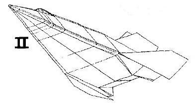
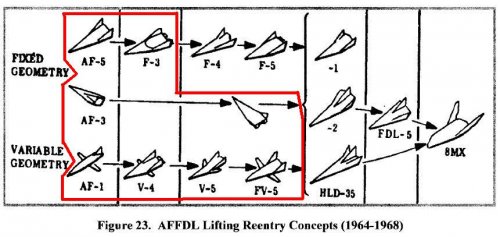
The FDL series 5, 6, 7, 8 and well as the F-4, F-5 and HLD-35 have been quite well described in this thread and others. http://www.secretprojects.co.uk/forum/index.php/topic,11504.msg109405.html#msg109405
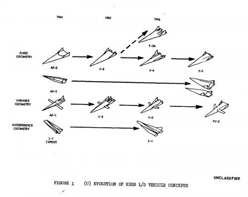
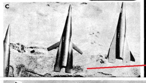
But is there some more information (2V or 3V drawings) available about the AFFDL previous models such as the AF, V and FV series, the FDL-1 to FDL-3 (ref.: Dynoman's previous post in this thread) and ... the WADD I & II.
Thanks in advance!
But is there some more information (2V or 3V drawings) available about the AFFDL previous models such as the AF, V and FV series, the FDL-1 to FDL-3 (ref.: Dynoman's previous post in this thread) and ... the WADD I & II.
Thanks in advance!
Attachments
- Joined
- 16 December 2010
- Messages
- 3,800
- Reaction score
- 4,188
Retrofit
ACCESS: Top Secret
- Joined
- 21 February 2007
- Messages
- 656
- Reaction score
- 337
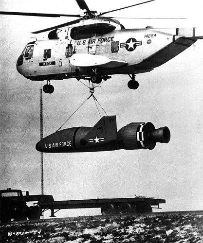
Graham1973 said:Just for the sake of completeness, from the now defunct Model Builders Reference Vault, the X-RV from Marooned.
Interesting, thanks Graham!
Sorry, forget my question:
http://www.secretprojects.co.uk/forum/index.php/topic,7459.msg64777.html#msg64777
OM
ACCESS: Top Secret
Graham1973 said:Just for the sake of completeness, from the now defunct Model Builders Reference Vault, the X-RV from Marooned.
...Last word I got Phil Broad was going to either find a new and cheaper hosting service and put the site back up, or get someone to volunteer to take the site and its contents over. In either case, he's limited in how much time he can spend on keeping things updated.
- Joined
- 31 December 2006
- Messages
- 802
- Reaction score
- 363
Similar threads
-
-
-
Secret Flight Test History - An Alternate History of the X-24C
- Started by Dynoman
- Replies: 27
-
-

