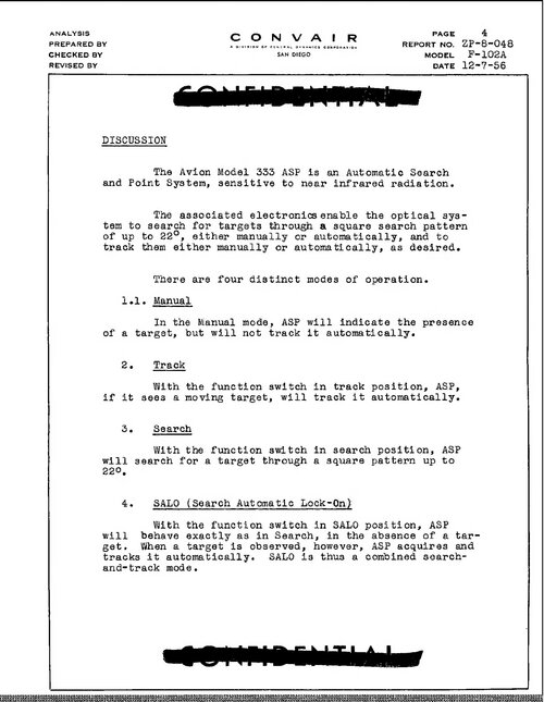
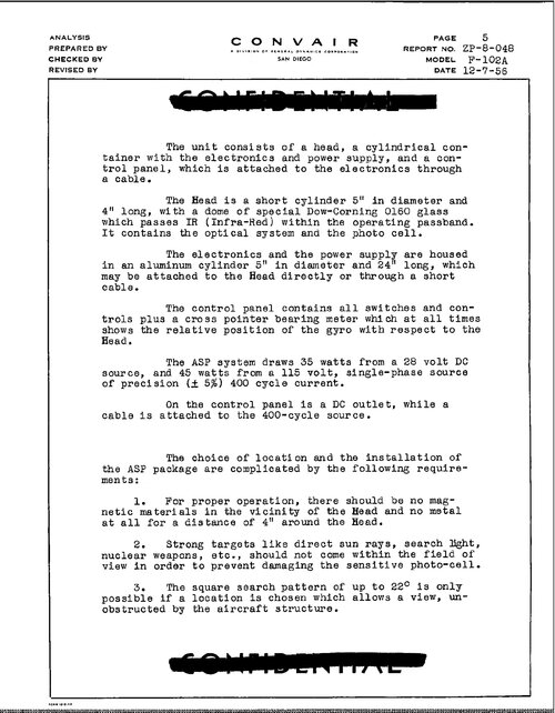
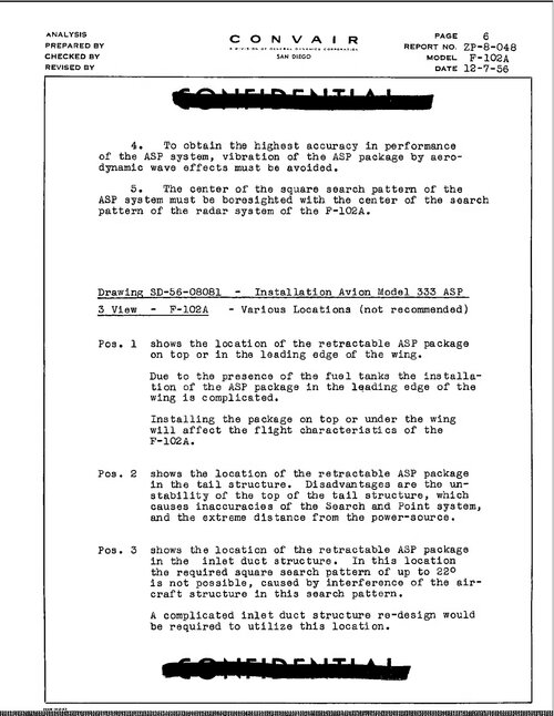
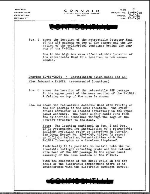
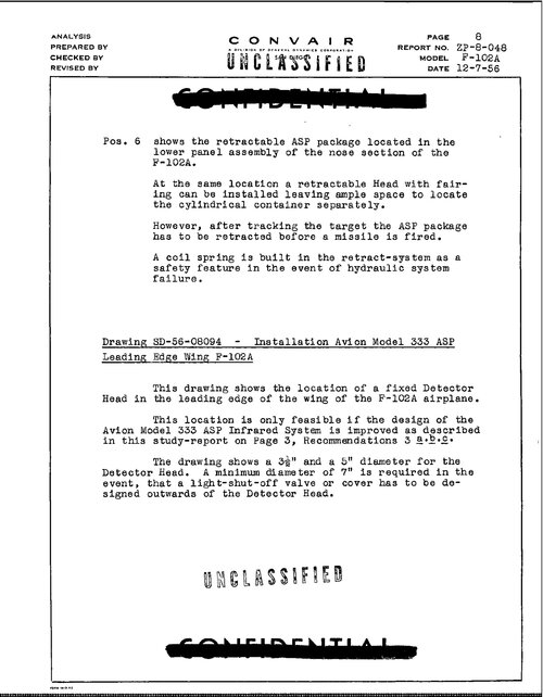
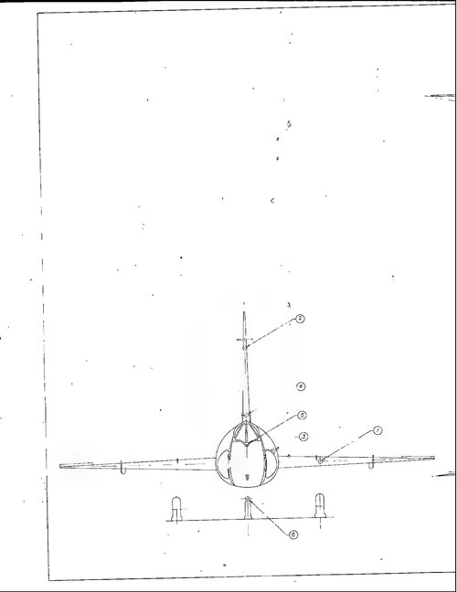
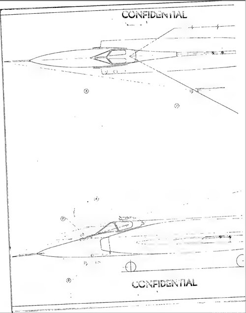
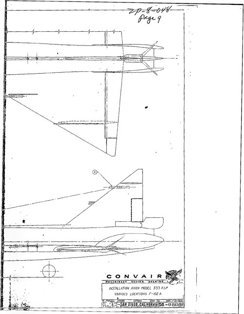
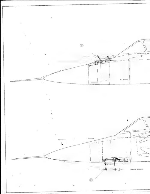
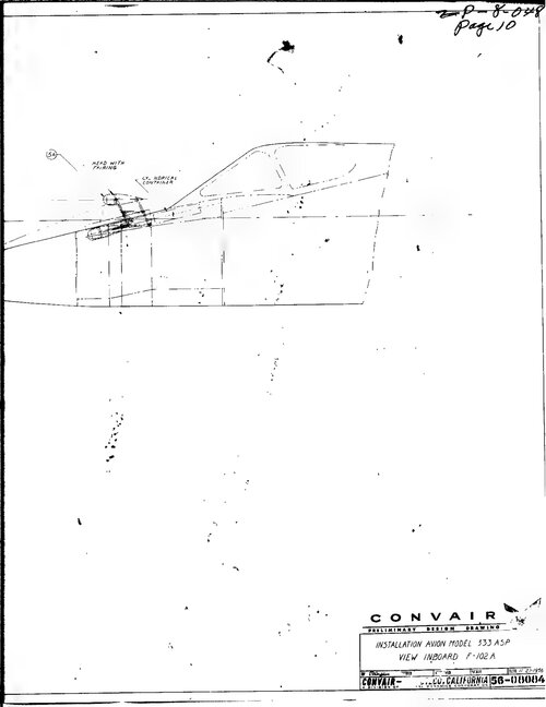
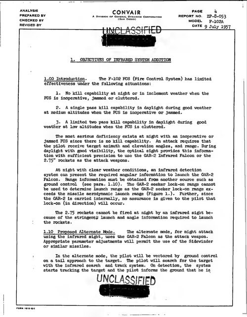
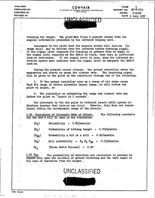
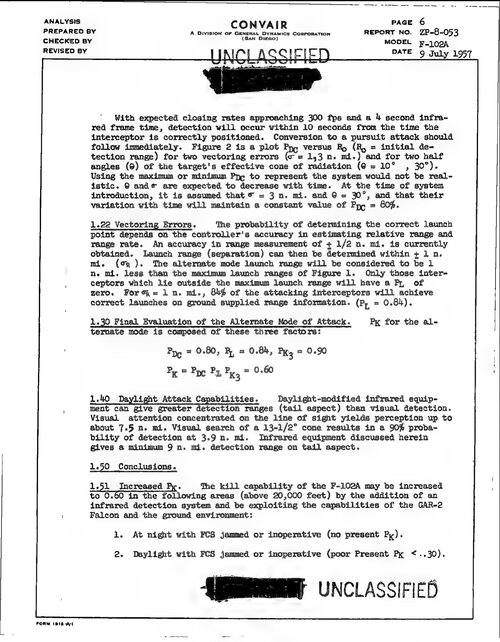
INFRARED DETECTING SYSTEM
Note
Refer to NATOPS Flight Manual for additional information.
DESCRIPTION
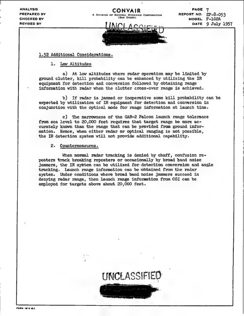
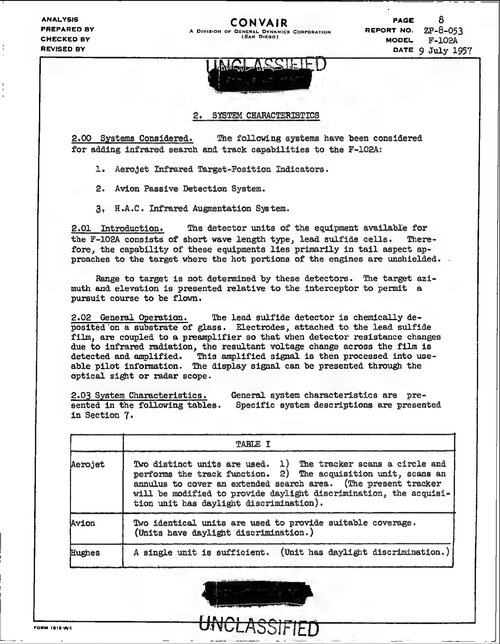
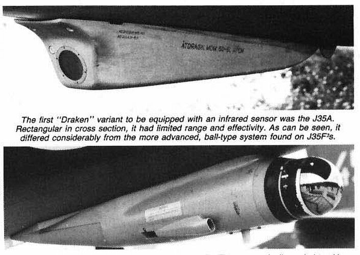
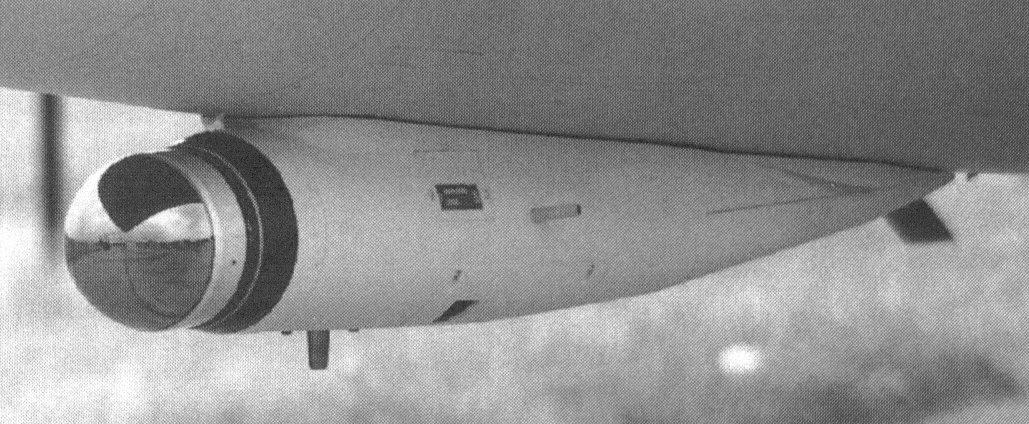
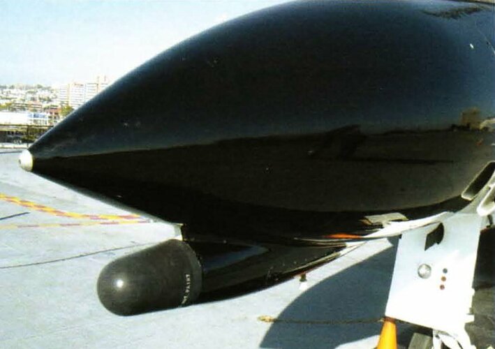
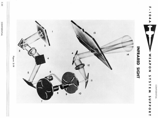
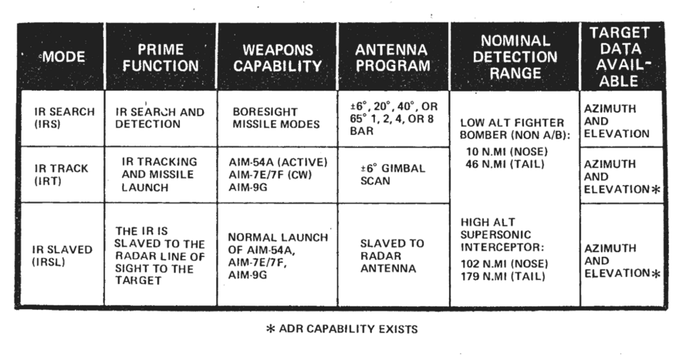
The infrared detecting set operates in three modes. These are IR search, IR acquisition, and III track. In these modes, IR data is displayed on the radarscope.
The IR. tone (200 to 2,000 cps depending on signal strength) is available in all modes, including radar modes.
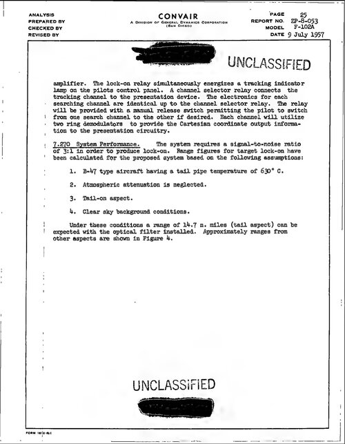
While operating in either acquisition or track, an IR lamp will illuminate when the III detector elements receive sufficient IR energy. This will occur in either radar or IR mode. Steady illumination while operating in acquisition or track is an indication that the target is illuminating the elevation IR detector. If the IR lamp is illuminated and the IR tone is present when operating in radar track, it is possible (but not a requirement of the system) to change to IR track and maintain a lock-on. However, since range information is not available during IR operation, a lock-on cannot be maintained when changing from IR. track to radar track.
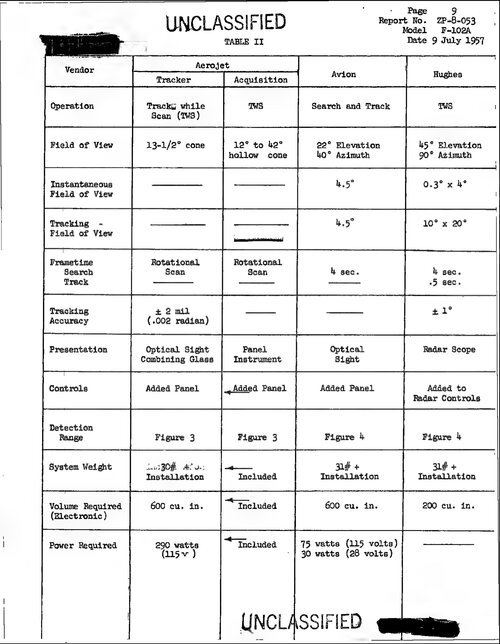
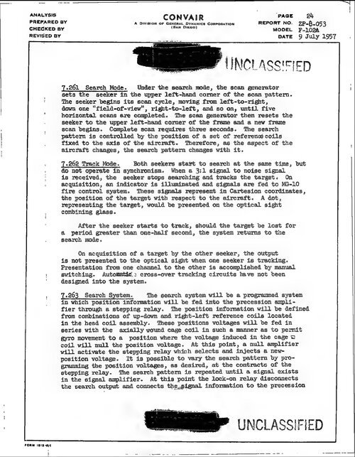
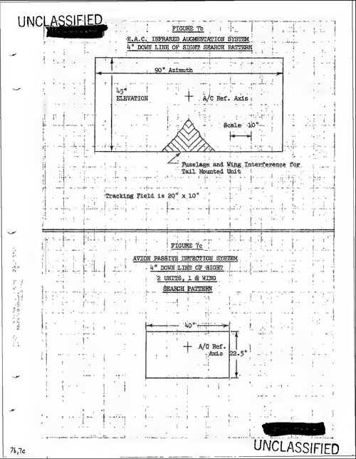
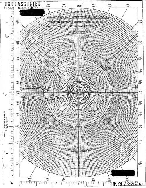
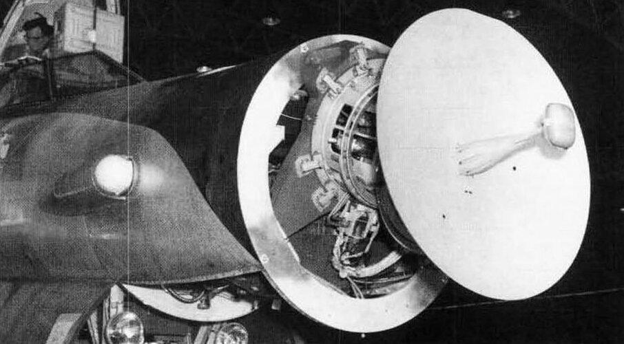
In IR search mode, the infrared detecting set receiver head is slaved to the radar antenna and searches a 4-bar scan pattern ahead of the aircraft. The search pat tern encompasses an area 38* to the left and 38° to the right of the aircraft boresight line in azimuth and a vertical arc of 7.9®. When left scan is selected, the IR receiver head sweeps a sector from 38° left 'to 10® right of the boresight line. In right scan, a sector 38° right to 10° left is swept. Center scan sweeps a sector 20*5 each side of centerline. The elevation plane of the search pattern may be .moved from. 45° above hori zontal to 30° below horizontal.
In the IR acquisition mode, the motion of the IR receiver head is still slaved to the radar set antenna and is controlled by the pilot’s radar control grip.
In the IR track mode, the scope display presents the position of the target relative to the aircraft 'bore sight line. The display consists of an aiming circle, aiming dot (/when the target is within 9® of the air craft boresight line), and a target signal strength line.
When the aiming dot is centered in the aiming circle, the target is dead ahead.
OPERATION
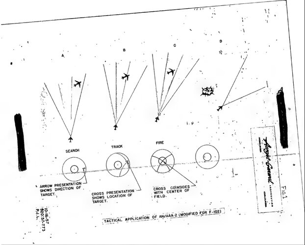
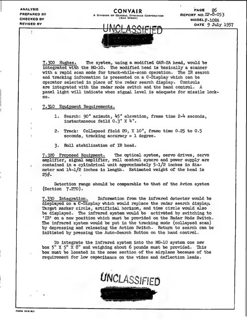
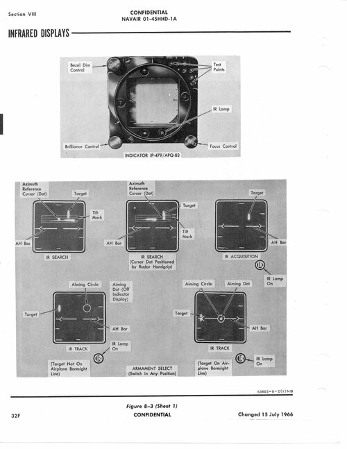
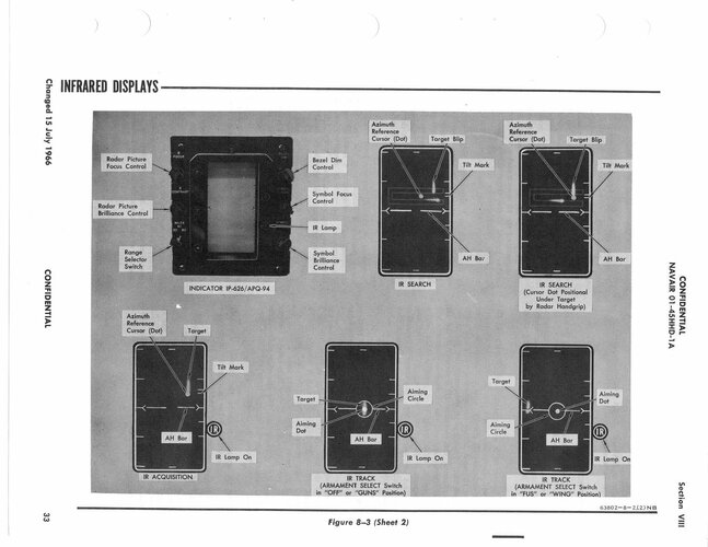
Scope displays showing the various modes of infrared operation are presented in figure 8—3, The power switch (27, figure 8—1) on the radar set control panel also controls power to the IR detecting set. When the switch is placed in st by , warmup power is supplied to the set and the nitrogen tank is pres surized to cool the detector cells to their operating temperature. When the power switch is placed in NOR with the mode switch in IR, search operation is ini tiated. For approximately 60 to 120 seconds a test target will appear on the lower right-hand side of the scope (approximately 20® below center) to allow a brief check of the IR search and. track capabilities. If another period of test target display time is desired, the power switch can be returned to STBY momen tarily and. then switched back to NOR.
In the search and acquisition modes of operation, movement of the antenna elevation, control knob (15, figure 8—1) on the radar control grip raises and lowers the search scan pattern. Side to side movement of the radar control grip (14, figure 8—1) moves the azimuth reference cursor laterally on the radarscope. The acquisition switch (19, figure 8-1) on the .radar con trol grip switches the set through the various modes of operation.
Movement of the IR receiver head along the 4-bar search pattern is indicated on the radarscope by a corresponding movement of a trace. When a target is encountered, the trace is intensified and deflected vertically to form a spike, and a "ping” (the IR. tone) is heard in the headset as the receiver head crosses the target.
When the acquisition switch is depressed, the search scan will stop and the IR receiver head is controllable in azimuth and elevation by use of the radar control grip and the elevation control knob. When it is desired to switch the set to the track mode, the acquisition switch must be released. Whether the target has or has not been acquired, the set will change from acquisition to track.
Once the acquisition switch is depressed, acquire the target and release the acquisition switch as rapidly as possible. The error signal system accumulates electrical energy during acquisition when the mechanical axis of the receiver head is not aligned 'with the target. This energy, which is fed. to the receiver azimuth and. eleva tion gimbal drive motors to keep the receiver head pointed at the target, can become excessive. When the
acquisition switch is released and the receiver head is not precisely aligned with the target, the drive motors may reposition the receiver head with a force sufficient to drive it through and off the target and break the lock-on.
The following are indications that tracking has not been initiated upon release of the acquisition switch:
• Vertical signal-strength line collapses to a dot. • IR tone frequency drops. • Steering circle drifts aimlessly. • IR lamp extinguishes.
Depress and release the acquisition switch if it is desired to return the set to the search mode. The search scan may be noisy for a short time after returning to search mode until the optical system stops rotating.
To be able to use the IR system with an AN/APQ-94 radar, the crystal oscillator BuOrd 2155846-1, -2, -3, or -4 must be installed in the electrical (missile) syn chronizer SN-253/APQ-83. Check for installation of the crystal oscillator (silver can through a glass win dow located in the top of the synchronizer in (aft end of the right-hand console).
TRACK AND SEARCH PROCEDURES
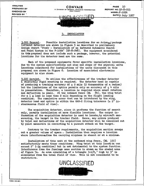
1. Search scan pattern — position • Adjust elevation of scan pattern to search de sired area. • When a target is encountered, position the scan pattern in elevation so that the target spike appears on the second or third bar. If the tilt mark is below the middle range mark, the IR system may detect ground targets.
2. Azimuth reference cursor — position • Move the azimuth reference cursor to the same azimuth position as the target.
3. Acquisition switch — DEPRESS • When the IR trace is sweeping the bar that pro vides the target spike, depress the acquisition switch. • The search scan will stop, and the IR receiver head will point in a direction corresponding to the position of the azimuth reference cursor.
4. Elevation — adjust • Adjust elevation until IR lamp is on steady, indicating that the target is being detected in elevation.
5. Azimuth — ADJUST • Sweep target in azimut huntil the spike exhibits maximum amplitude and brightness and the highest pitched IR tone is heard. 6. Acquisition switch — RELEASE • The acquisition switch must be released, to switch the set to the track mode. • Monitor the scope closely to ascertain that the desired target is being tracked. The steering in formation should move to the desired area, the IR lamp should remain on steady, and the IR tone should remain at a high pitch level. • As the target signal strength increases, the IR tone will increase in pitch. When it reaches the upper end of the frequency range, the target is in close proximity.
RANGE BURST FEATURE
The Range Burst feature* provides the AWG-4 Weapons System with radar range information for utilization during IR mode. When tracking an IR target, position the MODE switch on the Radar Control Panel briefly (3 to 5 seconds) to RADAR-NOR. position.
The radar will enter the Acquisition mode. Radar target range and azimuth information will be displayed on the radarscope. The radar target may be acquired if desired at this time by placing the acquisition bar be low the target, or it may be re-acquired in IR mode by returning the Radar Mode switch to IR.

