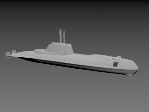
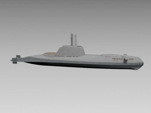
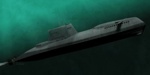
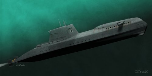
Unbuilt Type-XXIX u-boat

Wow!

Re the small deck behind the sail, possibly it was much more rounded rather than tapering into a point. But it's one of the features that is harder to determine from the schematics.
 
Yes that's how I think it is, although it's unclear in the schematics. But definitely not tapered to a point.

Are you planning to render the model? It's incredible btw.
 
Thanks!

Yes, I'd like to my hand at some underwater renders.
 

Attachments

  • Type XXI XH - 12.jpg
    Type XXI XH - 12.jpg
    109.5 KB · Views: 209
Looks good, nice work.
 
Apparently sail markings became rarer because the use of snorkels meant that the subs spent less time surfaced.

But the sail art on ww2 German subs was great so maybe add some anyway
 
covert_shores said:
Apparently sail markings became rarer because the use of snorkels meant that the subs spent less time surfaced.

But the sail art on ww2 German subs was great so maybe add some anyway

I know it's a cliche, but . . .

cheers,
Robin.
 

Attachments

  • e82d3ec09998ee318adf7a0219f850eb--movie-t-shirts-nose-art.jpg
    e82d3ec09998ee318adf7a0219f850eb--movie-t-shirts-nose-art.jpg
    75.6 KB · Views: 509
Really beautiful renders!
I believe that the waterline should be raised to a level just beneath the flood-holes.
 
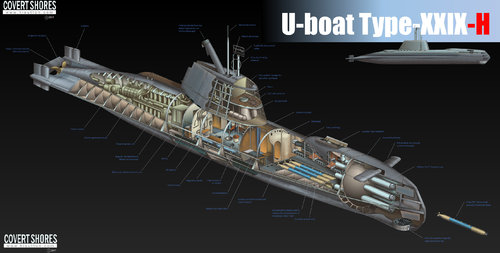
Now with markings and higher waterline ;)
 

Attachments

  • Type XXIX XH - 16A small.jpg
    Type XXIX XH - 16A small.jpg
    528 KB · Views: 494
Wow, really, really beautiful!

Now I guess you could add hypothetical details in absurdum...
Maybe it would have had a door in the aft side of the fin (one like those on type XXI fin side) for access to the aft platform?
Maybe it would have hade more small flood holes (like on XXIII) on the after top of the fin?
Maybe...

However - super nice renders!

//Fredrik
 
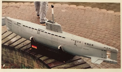
Here is a model made by a german model builder sometime around 1990.
This pic is from one of Eberhart Rösslers books.
It's the Type XXIX G which was an electro-uboote version of the hydrogen-peroxide powered Walther-turbine Type XXVI W.
No idea how accurate it is in details like flood-holes, but it looks plausible.

///Fredrik
 

Attachments

  • xxixG(2).jpg
    xxixG(2).jpg
    958.8 KB · Views: 414
Aha, a much better pic of the model there.
Du you have any more information about the model?
Maybe who made it and based on what information it was built?

///Fredrik
 
excellent thread and 3D work!
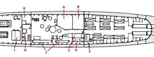
The illustration is coming along but unclear on some internal features. Have guesses but looking for second opinions. Anyone want to opine on the labeled rooms/objects in the attached?
44F44754-5A9D-43A1-844D-175A2766FFC4.jpeg
As to your three year old questions, some belated answers:
A = Ortungsraum = detection room [as per Gröner: assumed at the time of the XXIX H concept, August 1944, was the following equipment for a 1945 built XXIX H: hydrophones (Balkon-GHG, TAG), active sonar (SU-Gerät), radar (FuMO 84 Berlin II, FuMO 391 Lessing), passive radar detectors (FuMB Athos)]
B = Funkraum = radio room
C = Kommandantenraum = commanders room, with a curtain to the passageway
D = commanders bed/ bunk
F = Waschraum mit WC = lavoratory with toilet (and two sinks; next to toilet could be a shower?)
G = Proviantraum = food storage room (the square therein could be a freezer?)
H = Kombüse = galley (with single wash wasin and twin hot plates; the large circle is a cylindrical device for washing dishes)
I = ? (but some engine operators' panel seems an excellent guess)
J = Sauerstoffflaschen (oxygen bottles)
 
Last edited:

First off, I was thrilled to see your above mentioned article and the 3D work on this fascinating 1944 U-boat concept, Type XXIX H.
So much so that it caused me to sign up to this forum.
Thank you so much for creating and sharing!!

I do not at all want to nitpick. Since your work is currently the internets' top depiction of the Type XXIX H it would be great to have it most precise. Being an expert in WW2 German military hardware and having studied the books of Eberhard Rössler and Erich Gröner in the German language, I am in a position to point out a few "assumption errors" visible in your cutaway illustration:
- the rear periscope would have extended through the deployed snorkel mast, not next to it. It was called "Sehrohrschnorchel" - periscope snorkel. Types XXIX G and H were explicitly designed for quiet running at high snorkel speeds. Snorkeling had to be done while using a periscope in order to spot Allied ASV planes approaching. In order to prevent the periscope from vibrating at high underwater speeds (I assume XXIX H could have snorkeled with both diesel engines at flank speed, likely 11-13kn!) the observation periscope was to have been raised through the deployed snorkel, close behind the snorkels' leading edge, and thus been stabilized by the snorkel, preventing periscope vibrations.
- in addition to the folding snorkel, a 1945 XXIX H would have had 6 "Ausfahrgeräte" - vertically extending devices/ masts; viewed from rear to front:
1) a rod radio antenna or FuMO 391 Lessing active radar (rod shaped) on a mast on the left hand side
2) observation periscope (goes through snorkel) in the center
3), 4) FuMB 35 Athos radar receiver on a mast on the left (picture at https://slideplayer.com/slide/16459318/) side by side with FuMO 84 Berlin active radar ("inverted small bowl" shaped, sketch at http://www.lexikon-der-wehrmacht.de/Bilder/UVersuch/Typ29.jpg right behind the bridge) on a mast on the right
5) attack periscope in the center
6) Peilrahmen (direction finding ring) to the left of the bridge
(In your model you have only 4 vertically extending devices/ masts; and Hohentwiel would not have been fitted as the 9cm FuMO 84 was much superior and production was scheduled for summer 1945).
- the engine modeling is a bit fuzzy. In the sketch shown in Rösslers book it is quite clear: two 580hp diesel engines side by side: one standing alone driving a generator attached to it, the other without a generator being coupled with the 1400hp main electric motor.
 
Last edited:
One puzzling aspect about this Uboat concept is the number of torpedo reloads.
Both Gröner (p.138 of Book 3 of "Die deutschen Kriegsschiffe 1815-1945") and Rössler (Annex "Hauptangaben U-Boote" in Book 2 of "Geschichte des deutschen U-Bootbaus") state a total of 6 torpedo tubes and 10 torpedoes. Meaning that there would have been 4 torpedo reloads in the bottom half of the bow torpedo room.
On the other hand, the drawing in Rösslers book appears to show 6 torpedo reloads (two rows of three side by side).

In fact, the wash room in the corner of the bow torpedo room would have partially extended over tail sections of the rightmost torpedo reloads, complicating any torpedo storing or reloading.
I wonder why the discrepancy, and what the answer is...

One must keep in mind that many of the drawings/sketches in Rösslers book are post-war reconstructions done by one of Rösslers associates, not original wartime drawings...
 
Last edited:
Most interesting subject. And the 'reconstruct' work on the source material is so carefully thought out as to draw attention to this boat as a possible modeling (real modeling) project.

David
 
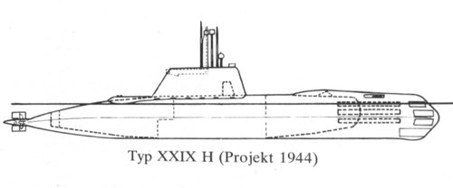
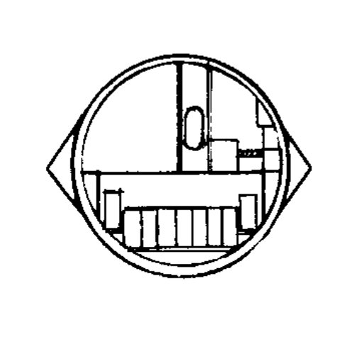
Gröner has this sketch in his above mentioned book.

observations:
-all boundaries of the pressure hull are indicated
-hull seems to be segmented into only three pre-assembled sections (Type XXI: eight hull sections)
-the line of the ASDIC deflecting side contour is displayed, showing a drop at the rear
-there seems to be a splash guard at the front of the bridge
 

Attachments

  • 0697B6FF-3B0E-46A2-B76A-0E899F447D17.jpeg
    0697B6FF-3B0E-46A2-B76A-0E899F447D17.jpeg
    79.9 KB · Views: 232
Last edited:

First off, I was thrilled to see your above mentioned article and the 3D work on this fascinating 1944 U-boat concept, Type XXIX H.
So much so that it caused me to sign up to this forum.
Thank you so much for creating and sharing!!

I do not at all want to nitpick. Since your work is currently the internets' top depiction of the Type XXIX H it would be great to have it most precise. Being an expert in WW2 German military hardware and having studied the books of Eberhard Rössler and Erich Gröner in the German language, I am in a position to point out a few "assumption errors" visible in your cutaway illustration:
- the rear periscope would have extended through the deployed snorkel mast, not next to it. It was called "Sehrohrschnorchel" - periscope snorkel. Types XXIX G and H were explicitly designed for quiet running at high snorkel speeds. Snorkeling had to be done while using a periscope in order to spot Allied ASV planes approaching. In order to prevent the periscope from vibrating at high underwater speeds (I assume XXIX H could have snorkeled with both diesel engines at flank speed, likely 11-13kn!) the observation periscope was to have been raised through the deployed snorkel, close behind the snorkels' leading edge, and thus been stabilized by the snorkel, preventing periscope vibrations.
- in addition to the folding snorkel, a 1945 XXIX H would have had 6 "Ausfahrgeräte" - vertically extending devices/ masts; viewed from rear to front:
1) a rod radio antenna or FuMO 391 Lessing active radar (rod shaped) on a mast on the left hand side
2) observation periscope (goes through snorkel) in the center
3), 4) FuMB 35 Athos radar receiver on a mast on the left (picture at https://slideplayer.com/slide/16459318/) side by side with FuMO 84 Berlin active radar ("inverted small bowl" shaped, sketch at http://www.lexikon-der-wehrmacht.de/Bilder/UVersuch/Typ29.jpg right behind the bridge) on a mast on the right
5) attack periscope in the center
6) Peilrahmen (direction finding ring) to the left of the bridge
(In your model you have only 4 vertically extending devices/ masts; and Hohentwiel would not have been fitted as the 9cm FuMO 84 was much superior and production was scheduled for summer 1945).
- the engine modeling is a bit fuzzy. In the sketch shown in Rösslers book it is quite clear: two 580hp diesel engines side by side: one standing alone driving a generator attached to it, the other without a generator being coupled with the 1400hp main electric motor.
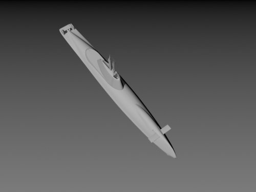
Thanks, hadn't seen this feedback. Might update my illustration if I can find time
 
Alright, I'm extremely late to this, so much so that everybody in this thread has probably already forgotten about this topic, but I'm still keen on sharing some info in case anyone is still interested.

Now with markings and higher waterline
Fantastic rendering, although the previous depiction is a bit more accurate, especially when it comes to the higher "waterline". The edge where the sloped outer hull parts would meet is actually in the middle (or just below torpedo tubes three and four), and not where the waterline would be (see picture). To indicate a higher waterline, the darker paintwork could be raised to where the uppermost set of torpedo tubes is located.

One puzzling aspect about this Uboat concept is the number of torpedo reloads.
Both Gröner (p.138 of Book 3 of "Die deutschen Kriegsschiffe 1815-1945") and Rössler (Annex "Hauptangaben U-Boote" in Book 2 of "Geschichte des deutschen U-Bootbaus") state a total of 6 torpedo tubes and 10 torpedoes. Meaning that there would have been 4 torpedo reloads in the bottom half of the bow torpedo room.
On the other hand, the drawing in Rösslers book appears to show 6 torpedo reloads (two rows of three side by side).

In fact, the wash room in the corner of the bow torpedo room would have partially extended over tail sections of the rightmost torpedo reloads, complicating any torpedo storing or reloading.
I wonder why the discrepancy, and what the answer is...

One must keep in mind that many of the drawings/sketches in Rösslers book are post-war reconstructions done by one of Rösslers associates, not original wartime drawings...
You made some great points, and I believe I can help with the torpedo reload conundrum. Looking at type XXI, we know that it could have a maximum of 17 torps in addition to those in the tubes. However, in practice, it could only carry 14 reserve torpedoes, because the fish needed to go through regular check-ups. To move the torpedoes into a position where they could be checked, the sub's torpedo reload system needed three free spaces, thus reducing the total amount of torpedoes to 20.
The same was probably also the case for type XXIX H: two torpedo spaces had to be vacant to make the other four torps accessible for check-ups.
And by the way, I'm pretty sure that the sketches typically provided for this type by Rössler in various books are *not* reconstructions.
Gröner has this sketch in his above mentioned book.

observations:
-all boundaries of the pressure hull are indicated
-hull seems to be segmented into only three pre-assembled sections (Type XXI: eight hull sections)
-the line of the ASDIC deflecting side contour is displayed, showing a drop at the rear
-there seems to be a splash guard at the front of the bridge
Some more good points in this post, but I'm pretty sure the sections indicated in this sketch don't indicate pre-assembled hull parts, but simply the pressure-tight sections of the sub. Still, if this type had gone into mass production, it's quite possible that similar methods to those used for type XXI would come into play, including the quite revolutionary use of pre-assembled sections.

Here is a model made by a german model builder sometime around 1990.
This pic is from one of Eberhart Rösslers books.
It's the Type XXIX G which was an electro-uboote version of the hydrogen-peroxide powered Walther-turbine Type XXVI W.
No idea how accurate it is in details like flood-holes, but it looks plausible.

///Fredrik
The most perplexing thing in this thread was this model though. Apparently, this is supposed to be a depiction of type XXIX G, which I never saw a proper sketch for (quite possibly because it didn't survive the war), but I do have some information from Gröner. The design was described as having an 8-shaped pressure hull and four blocks of 62 MAL 740 E battery cells, which sounds very reminiscent of type XXXI. This model here looks very much like XXX A, just shorter and with a different sail as well as a different allocation of torpedo tubes (six bow torpedo tubes and six side tubes instead of eight bow and four to the sides). Additionally, type XXIX G was reported to have been redesigned to incorporate the innovations of XXIX H, including the stealthy "Kantenform" ("edge shape"). This type was designated XXIX GK, but I don't think this shape could've been easily implemented on a sub that looks like the photographed model.
Last but not least, I would like to say thank you for this amazing cutaway. Looks fantastic, and I always appreciate how you dare to shed light on submarines almost nobody has even heard about. I could go on for much longer on how intelligent various aspects of this design are, and personally, I hold XXIX H as the pinnacle of German WW2 submarine design (at least when it comes to large subs, German midget subs were similarly advanced for different reasons, like Delphin, which foreshadowed one of the most important aspects of American post-war subs with its teardrop shape).
It's worthy of note that the principal designer of XXIX H is Ulrich Gabler, who was also one of the pioneers of German post-war submarines, making it indeed very likely that it influenced later generations of submarines, even to this day with type 212 CD.
 

Attachments

  • 29.PNG
    29.PNG
    29.6 KB · Views: 111
@nonenamesunder the ironic part about the body of revolution subs is that this shape is what was seen very early. It was not a WWII development at all, nor a WWI development. There were shapes in the 1800's and even potentially arguably earlier depending on how strict you take a hull of revolution/teardrop shape. The main challenge with it that was solved later was the fact that most submarines were not true underwater machines, but ships that dove. Due to the fact that they tended to transit on the surface, caused the need that they had good surface keeping abilities. Advances in propulsion is what allowed the hull of revolution/teardrop hullform to come back. Shapes that did not need to deal with the surface keeping issue such as torpedoes had the more ideal form already. It could also be found in short range submarines. These were your midget class submarines, and despite this, lack in other areas caused the lack of seakeeping to still cause challenges. Midgets like the Seehund while not pretty were generally more successful than other midgets such as the Japanese Type A which had a more streamlined shape.
 
I'm aware that such a shape was "invented" neither by the Americans nor by the Germans. And indeed, this shape can be traced back through the centuries. Ictineo II is a good example of a way earlier sub that gets the shape roughly right. Of course, there were many projects with a quasi-teardrop shape before Delphin, even in Germany. A lot of the early projects of Hellmuth Walter (starting in 1932) looked like this. Delphin still has an interesting place in all of this. It had an unusually high admiralty constant (especially for a midget sub!) of Cw = 210, and that's before it received further streamlining around its plexiglass hatch. For comparison, Seehund had a value of 70. Simply put, Delphin was arguably the first time a "pure" teardrop shape was not just a feasible solution for a military submarine, but the also best. Despite only being powered by a 32 hp motor, it was capable of 17-18 knots. These feats make Delphin particularly salient among other designs that had a superficially similar shape.
 
Last edited:
You made some great points, and I believe I can help with the torpedo reload conundrum. Looking at type XXI, we know that it could have a maximum of 17 torps in addition to those in the tubes. However, in practice, it could only carry 14 reserve torpedoes, because the fish needed to go through regular check-ups. To move the torpedoes into a position where they could be checked, the sub's torpedo reload system needed three free spaces, thus reducing the total amount of torpedoes to 20.
The same was probably also the case for type XXIX H: two torpedo spaces had to be vacant to make the other four torps accessible for check-ups.
I believe you must be right!

From what I recall reading, loaded torpedoes needed to be pulled ca. 30% of their length out of their tubes for maintenance every couple of days.
Accordingly, while there was space for 6 spares below the crew compartment, the space directly behind the two lowermost tubes had to be kept free for this maintenance.
So we also now know the precise location of the four spares in the reserve torpedo compartment below the crew compartment: bottom row: 3; top row: 1, in the center

I also now believe I can deduce some mechanics and arrangements in the bow crew compartment:
torpedo loading/ unloading in port:
for this, 2 walls of the sanitary cabin (full gangway wall and part of the forward facing wall) had to be dismounted, as well as the center bunks (3x3 beds) and their walls and supports, and much of the bows floor plating. Then, 6 torpedoes were loaded into the torpedo storage compartment (first down in the center, then slid sideways), and 2 of these go into the bottom 2 tubes; next: 4 more torpedoes for the 4 topmost tubes; afterwards, floor, walls and bunks are restored

sanitary cabin:
it likely had a one piece floor plate that was fixed and non-removable; next to the toilet is something that looks like a shower stall; I presume it was for showers, for rinsing clothes, and also to used as a urinal (this would have relieved the "stress" of only having a single toilet for 27 crew)

torpedo reloading while underway at sea:
due to the sanitary cabin floor floor plate partially extending over the spare torpedo area, it appears that the top right and middle right tube would never be reloaded at sea with torpedoes from below (as this would have required removing walls of the sanitary cabin). The 4 reloads thus go into the other 4 tubes.
The minimally invasive way would be to always only reload the two bottom most tubes. For this, part of floor plating (an area directly behind the tubes) need to be removed, hoisting gear attached, and torpedoes raised to bottom tube level. (The two spare center torpedoes first need to be slid sideways before upwards or forwards movement)
 
Last edited:
Good insights! I wasn't 100% sure how the torpedo reloading process was supposed to work and the precise reasoning for those two vacant spaces, but you seem to have cracked the code. I assume this type's shower is the same as the one already implemented on Type XXI, although the latter seemed to not have it enclosed in an extra stall.
However, I'm confused about you saying that removing the walls of the sanitary cabin is required to reload the top right and middle right tube. I think I know what you mean, but you may have missed the mark a bit in your description. The likely non-reloadable tubes are on the port side of the boat. If you're using the same blueprints I have (the ones provided by Rössler in his books on Type XXI, German Sonar developments, and overall German submarine history), don't be misled by the cross-sections at the bottom! They are from a consistently frontal point of view, i.e., what is to the left on these drafts would be on the starboard side for the submariner. Also, the walls that prevent reloading are, as far as I can see, not of the sanitary area, but of the portside crew quarters (the smaller ones with less bunks, likely for more senior personnel). I doubt these partitions would've been removable under the conditions of a normal patrol.
But maybe you meant what you said and actually referred to the actual sanitary cabin on the starboard side of the boat blocking any reloading of the tubes you mentioned. Personally, I doubt it would've been much trouble since the torpedoes might be just short enough to fit in the compartment even with the sanitary cabin. If not, that would imply to me that only two torpedo tubes (the lowermost ones) were practicably reloadable on patrol. Quite a severe restriction on combat capability if that was true. It also went against the late-war German submarine design philosophy of having as many torpedo tubes as possible ready to fire immediately instead of a larger number of reloads. To expend all of its torpedoes under the restrictive conditions described, Type XXIX H would have to make at least three separate attacks (shooting 6+2+2 torpedoes). In this sense, this type's torpedo arrangement can be seen as the least effective among those of the late-war German designs: It lacked both the highly automatised reloading system found on Type XXI and the larger number of torpedo tubes found on Type XXVI (10 TT) or the KIU-designed Type XXIX boats (8) among others.

I will add to this some more observations:
- The submarine had at least one life raft located in the container attached to the hatch in the conning tower (which was otherwise not pressure-tight and meant to be flooded while submerged). Type XXI had a total of six, so there might also be more hidden on this one.
- Diesel-electric transmission is, under certain conditions, quieter than direct-drive (though the opposite can also be true under different conditions). It is therefore possible, since Rössler mentions "improved noise sealing" as an innovation for this boat, that the diesel used as a generator is actually also used for quieter snorkelling operations.
- The top speed of 12 knots can likely only be reached when both the 580hp direct-drive diesel and the identical generator work together, with the latter feeding its power into the electric motor.
- The special edgy shape (K-Form) was supposed to be most effective against more or less horizontal sound waves. E.g., when a destroyer sends a ping, the shape protects best when the boat is in shallow depth. While this is a further restriction, this fact along with the introduction of better noise sealing and the periscope snorkel implies to me that the boat may also have been planned to approach enemy shipping while snorkeling, as these three advantages could be made full use of in this scenario, especially because this boat's submerged range (120 nm/6 kts on main motor; 225/4 on creep motor) would've been rather limited compared to the larger Elektroboot designs due to its reduced battery.
- The periscope snorkel that comes to use here was likely first designed by Heinrich Oelfken, "father" of Type XXI, who patented the snorkel design on 21th of April, 1945.
- I found a bit more info about Type XXIX G, which was assumed to be the submarine type depicted by that model earlier in the thread. While the model is indeed likely supposed to depict it, it's not perfectly accurate when compared to the early-stage blueprint I found. In essence, Type XXIX F and G were design studies similar to XXVI E in that they used XXVI W's shape, but with Batteries instead of hydrogen peroxide, which led to the addition of a lower Schale (bowl) to the otherwise circular pressure hull, making it somewhat 8-shaped. In this sense, it's similar to Type XXI, which is firmly rooted in the Type XVIII Walter sub. What I've come to wonder now is how the special shape of XXIX H would've looked on the GK variant with the K-Form. Since the pressure hull has a very different shape, it couldn't have been an exact copy of Type XXIX that only differs in size. Among the questions my deliberations have led to is whether Type XXIX GK's stern was shaped more like that of Type XXIX H or more like preceding designs with the Schneidenheck. Alas, I fear we will never get an answer, as I'm unaware of any source that gives more detailed info on these highly interesting projects other than Gröner and Rössler.
 
Last edited:

Similar threads

Please donate to support the forum.

Back
Top Bottom