Intake design and general stealth discussions

chuck4

ACCESS: Top Secret
Joined
17 January 2011
Messages
812
Reaction score
81
Serpentine intake ducts do not let radar waves travel a straight path to and from the fan or compressor blades of the jet engine. But as far as I can tell, there is nothing in the S-intake that is designed to specifically reflect radar waves back in specific directions aligned with the rest of the aircraft's radar reflecting properties. So am I correct in believing the S-duct primiarily relies causing the radar wave to lose strength through multiple internal reflections inside the duct, and through the use of RAM, to reduce radar signature?

If this is the case, then it appears the advantages of S-duct over integrated radar blockers in a straight duct must be minimal. The blockers can also be shaped to generate multiple internal reflections, and can also be coated with RAM materials.

Furthermore, it appears to me that should the designers wish to cause the inlet to be so configured as to align any reflection that escapes with the rest of the aircraft, it would be easier to do so with a set of blockers than with a serpentine duct.

Is there any reason why a flat fine wire mesh screen can't be through over the intake to make the intake appear as a completely flat, aligned surface when seen by radar? I know it was done with F-117, but it seems doable with any jet, provided the mesh is strong enough not be become foreign object damage to engine.

Comments?
 
chuck4 said:
Serpentine intake ducts do not let radar waves travel a straight path to and from the fan or compressor blades of the jet engine. ...

Comments?

Or is it that they do not allow the IGV, compressor blades to be visible ?

Stand in front of the intake on an older non-stealthy jet fighter or attack aircraft and the IGV, compressor
blades are quite visible from outside the inlet.

chuck4 said:
... it appears the advantages of S-duct over integrated radar blockers in a straight duct must be minimal. ...

Is there any reason why a flat fine wire mesh screen can't be through over the intake to make the intake appear as a completely flat, aligned surface when seen by radar? I know it was done with F-117, but it seems doable with any jet, provided the mesh is strong enough not be become foreign object damage to engine.

Comments?

I would be careful just adding blockers inside the inlet.

For one, the blockers not only block E-M waves but also the airflow to the engine.
On the F-117 they may have sized the inlet to compensate for the mesh blocker area
obstruction. In other words the inlet is larger than it normally would need to be
without blockers inserted.

For a subsonic F-117A that also will never have to diffuse the supersonic airflow
down to subsonic and also doesn't have an afterburner this would be OK.

For a F-22 or F-35 or lower RCS F-15 where the aircraft can fly well into supersonic
and thus has a supersonic inlet diffuser that needs to use shock waves to slow the air down
to subsonic and also has to handle moving the normal shock around in potential inlet unstarts,
and has a much wider performance range than the F-117A, adding obstructions to the inlet
doesn't sound like a good idea to me.

But I am not a stealth technology enthusiast at the moment. I prefer to spend my time on
hypersonic topics. Someday I'll get more into stealth. But the above would be my concerns
coming from just a airbreathing inlet technology standpoint.
 
The book: "Radar Cross Section", second edition has an excellent answer to your question. It was also
recently suggested by quellish. I would heartily suggest buying it to have it handy in cases such as this.

I grabbed my copy and looked up your question inside and immediately found the following interesting
explanation (as stated earlier I am not a stealth expert). I am looking forward though to going through
these books one day!

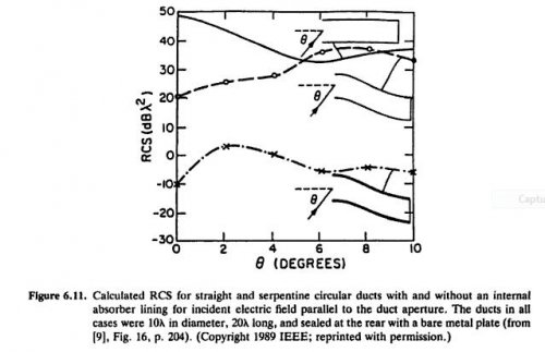
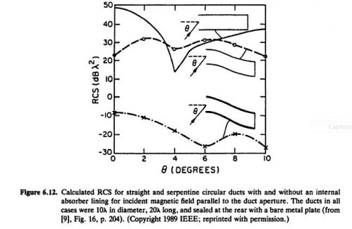
The following figures show the impact of an experiment on a straight metal duct without a radar absorber
lining (top solid line plot) and a compressor face at the end of the duct (modeled as a bare metal plate),
a metal serpentine duct without radar absorber lining (middle plot), formed by displacing the rear of the
duct one duct diameter from the duct inlet centerline, and a metal serpentine duct like the earlier one,
but lined with radar absorber (bottom plot).

The ducts were all of circular cross section of 10 lambda (radar signal wavelength) in diameter, and
20 lambda long.

The following plots were generated by a Cray X-MP running software that used the theory of geometric optics
in a ray tracing scheme to account for the distribution of the radar E-M fields over the intake aperture.

Namely, modelling the rays entering the duct aperture from 0 deg incidence (nose-on incidence) to up to
10 deg off (the x-axis in the plots), and then modelling the rays suffering internal reflecions due to
Snell's law, bouncing against metal walls (top plot and middle plot) or radar absorber lined walls
(bottom plot), reflecting against the compressor face (modelled as a bare metal plate) and bouncing back
against either the metal walls or the radar absorber lined walls, and passing back out the aperture at
angles possibly different from how they came in.

The vertical axis is the strength of the E-M wave coming back in dB lambda sq, and the x-axis as mentioned
is theta, the angle of incidence.

There are two plots because Fig 6.11 shows the incident electric field and Fig 6.12 show the incident magnetic
field (as you may remember an E-M wave has an E-field part and a normal B-field (magnetic field) part).

In the results, note that the metal serpentine duct with no absorber (middle plot) for both the E-field
and B-field are about 25 dB down at 0 degree incidence from the straight metal duct with no absorber. So
it looks like just making the duct serpentine with no ram may help. But! Note that at off nose-on angles
the srength of the serpentine with no ram liner reflection goes above the straight metal duct refection !

But the serpentine duct with ram liner is around 60dB down from the straight metal duct without absorber
at 0 theta incidence and if you compare the bottom plot (the serpentine duct with ram lining) with the
straight metal duct without ram (the top plot) the strength of the reflection is significantly lower
across the board of theta incidence angle. There is a region at around 3 deg off nose-on incidence for
the E-field and 4 deg off for the B-field where the ram lined duct is as close as 30-35 dB as the straight
metal unlined duct, but most of the incidence angles are around 50dB down and very significant.

In this experiment the dielectric constant of the ram absorber was relatively modest (it wasn't a huge
absorber) and was lambda/4 thick. The dB loss due to that ram config in a bistatic sense is -15dB to -5dB
depending on E-M field polarizaton and incidence angle. But it is the fact that multiple internal duct
reflections against the ram causes a large dB loss by the time the signal comes back out the inlet.

So, I'd get the book, it is quite good !!
 

Attachments

  • pg.240 Fig 6.11.jpg
    pg.240 Fig 6.11.jpg
    36.4 KB · Views: 123
  • pg.241 Fig 6.12.jpg
    pg.241 Fig 6.12.jpg
    38.5 KB · Views: 115
Sundog said:
This should interest both of you, though it's only supersonic, not hypersonic.

Boeing Stealth Inlet

So thanks for the reference. Though in my line of work we would never get caught dead
reading other companies patents. This is not my line of work so I looked.

It seems like this interesting "screen" has quite a bit of depth to it and could perhaps form
itself into a serpentin duct !

I have concerns however about how this screen interacts with shocks. It says it swallows
them OK, but I still have reservations. I'd need to see experiments run.

Also one reader mentioned the increase of skin friction drag caused by this screen as it
could greatly increase surface area depending how deep it is.

But it's definitely interesting!

Thanks Again !
 
shockonlip said:
It seems like this interesting "screen" has quite a bit of depth to it and could perhaps form
itself into a serpentin duct !

I have concerns however about how this screen interacts with shocks. It says it swallows
them OK, but I still have reservations. I'd need to see experiments run.

Also one reader mentioned the increase of skin friction drag caused by this screen as it
could greatly increase surface area depending how deep it is.

But it's definitely interesting!


This would appear to be an adaptation of a segmented/vaned supersonic diffuser used years ago in chemical lasers.

http://spie.org/x648.html?product_id=172723

The theory of operation is identical to that of the isolator in a dual-mode scramjet.
 
Correct points - The serpentine inlet works by (1) preventing any signal from reaching the compressor face and bouncing out without hitting the walls and (2) ensuring that any signal bounces as many times as possible on the way in and on the way out.

The result is that it doesn't take a lot of RAM to suppress the signal, because even a few dB down is quite a lot, multiplied over four of six bounces.

And there is not a lot of penalty if designed-in from the start (cf Typhoon). Actually, Typhoon and Rafale have neater inlets than F-35, which has to deal with a large-diameter engine installed a long way forwards.

Grills can be aerodynamically not-too-bad, and can be the right solution in length-constrained applications, but icing is a [lady dog].
 
When designing the S duct ensure that none of the radius are constant. Use nonlinear bezier curves in design of the "S" intake flow path and forward intake diameter. Or rectangular inlet lip shape to oval duct shape.
 
Grids affect the amount of pressure recovery you can get out of the inlet (ratio of total pressure at fan face over that in the freestream). Basically pressure recovery helps the engine cycle by increasing overall pressure ratio. Good pitot inlets are in the 98-99% range. As you lose pressure recovery, bad things happen to thrust and SFC, so compromises in inlet design come at a great cost in terms of performance.

On the plus side, inlet devices MIGHT have a good effect on pressure distribution at the fan face, but that's a different story.
 
For a super cruiser, what is the penalty of having a fixed serpentine duct vs a straight duct with variable shock cone/ramp and radar blocker?
 
chuck4 said:
For a super cruiser, what is the penalty of having a fixed serpentine duct vs a straight duct with variable shock cone/ramp and radar blocker?

I don't believe you can come to any general conclusion, as the devil is in the details.
 
Orphic said:

Orphic, if you had read 9 replies above yours you would have seen that your post has already been made.

Personally, I am skeptical of this Boeing patent. There is a lot of detail that is left out. Hopefully there
is still room for me to personally innovate if I decide to do so. But that is not helped if I read the details
of the patent.

I am actually surprised that AW&ST trolls these aerospace patents and then contaminates the
aerospace engineering community by publishing them.
 
chuck4 said:
For a super cruiser, what is the penalty of having a fixed serpentine duct vs a straight duct with variable shock cone/ramp and radar blocker?

So chuck4, a number of us attempted to help you out above. A simple "thanks" would certainly
motivate me to help you out more.
 
chuck4 said:
Furthermore, it appears to me that should the designers wish to cause the inlet to be so configured as to align any reflection that escapes with the rest of the aircraft, it would be easier to do so with a set of blockers than with a serpentine duct.

I'm not sure how a radar blocker inside the inlet would allow for a designer to align the turbine face reflectors with the primary external specular reflections, but maybe I am missing something?

chuck4 said:
Is there any reason why a flat fine wire mesh screen can't be through over the intake to make the intake appear as a completely flat, aligned surface when seen by radar? I know it was done with F-117, but it seems doable with any jet, provided the mesh is strong enough not be become foreign object damage to engine.

That is not actually the case with the F-117. For other apertures a fine wire screen was used, but not the inlets (for several reasons). The inlet "screens" were actually progressive absorbers of a sort. Ed Lovick, who designed them, covers this in some more detail in his book:
http://edtheradarman.com/

So, long story short, there are a lot of reasons not to put a screen over an inlet. This is why you don't see a lot of aircraft wearing them.
 
The DSI intake is not new.

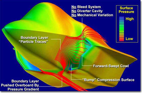
A DSI or diverterless supersonic intake is a fixed geometry intake which incorporates a 3D "bump" in front of the intake which diverts sluggish boundary air away from the intake. Here's the F-35 DSI showing how it works.

aTYpQhE.png


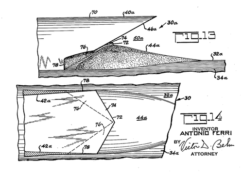
Despite what Lockheed might tell you, it's not something they invented in the 1990s. NASA research on intake design in the mid 1950s included Antonio Ferri's compression bump with forward swept scoop or "Ferri"intake.

Ferri-Intake.png
An object of this invention is to provide a novel construction of a scoop-type supersonic air inlet for the efficient conversion of dynamic pressure to static pressure. A further object of this invention is to provide a novel construction to facilitate starting of a Scoop-type Supersonic air inlet. Increases in static pressure, or compression, in a supersonic inlet can be accomplished by the physical turning of the air which results in the generation of compressive shock waves. A further object of the invention comprises the provision of a scoop-type air inlet having a novel aerodynamic compression surface (hereinafter termed a compression bump) for more efficiently producing compression in the inlet. In accordance with the invention, the compression bump is formed on the inlet surface adjacent to the aircraft body member from which the inlet projects so that only a part of the physical turning and resulting air compression required is produced by the inlet outer wall formed by the scoop, the rest of the required physical turning and resulting air compression being effected by the bump surface. The compression bump preferably is integral with the surface of said aircraft body member and its upstream end may be disposed upstream or downstream of the leading edge of said outer wall of the inlet. With the leading edge of said bump disposed upstream of the leading edge of said inlet outer wall, the presence of the bump also provides precompression of the air before the air enters the inlet thereby reducing the Mach number of the supersonic airstream before the air enters the inlet so that less air spillage is required to start the inlet. In addition, in the case of a three-dimensional bump, the bump imparts to the air flow a pressure gradient which is normal to the direction of the entering air thereby assisting in removal of the boundary layer of air adjacent to said body member and bump.


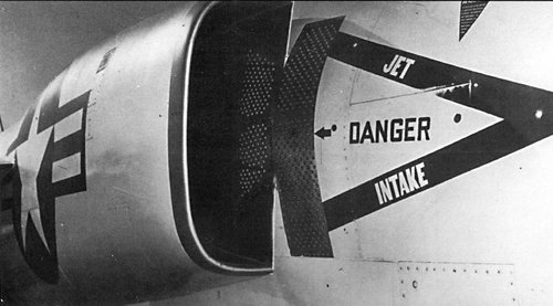
A somewhat related design of intake was used on the Grumman F-11F-1. However, the F-11F-1 bump was small and did not remove the boundary layer sufficiently - it required a porous surface behind the bump to remove boundary air.
XF-11F-1.jpg

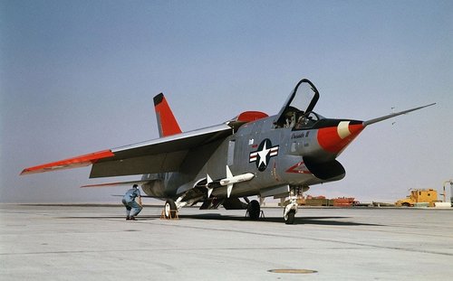
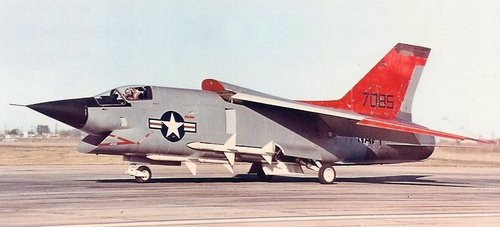
The F8U3 used a proper "Ferri" type intake design - the "compression bump" was formed by the underside of the nose, and the intake cowl swept forward very much as in the Ferri patent. It was able to reach Mach 2.2, limited by engines but not the fixed geometry intake.

F8U3-Crusader.jpg

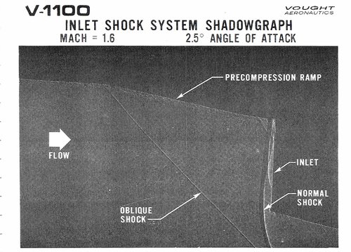
However after the 1950s, the complex fully variable intake became ''de rigueur'' in fighter design and the Ferri intake was largely forgotten, though not by Vought. In 1971-72 Vought designed a lightweight fighter, the V-1100, for the LWF competition which used a version of the Ferri intake for light weight and decent performance.

V-1100 Intake.JPG V-1100 Intake 2.JPG

General Dynamics studied a Ferri intake for their Model 401 LWF but ended up going for a fixed pitot intake with a splitter plate instead on what became the F-16.

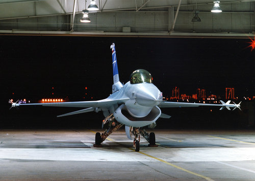
In the early/mid 1990s Lockheed (now including General Dynamics) did an extensive study on intakes and found that new CFD (computational fluid dynamics) analysis could model and predict air flows with much greater precision, allowing the fixed Ferri type intake to be more efficient, to the point it could match a more traditional intake design while being 30% lighter, and with benefits in terms of stealth.

They first tested it on an F-16:

2010_F16_DSI_02_1267828237_7281.jpg

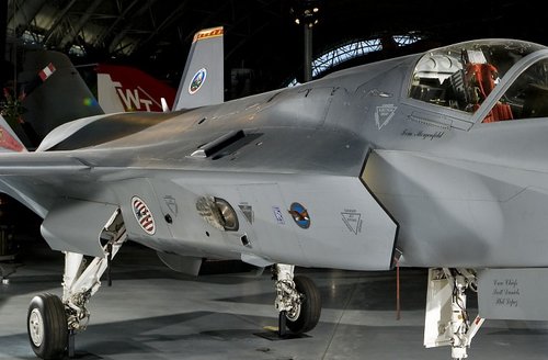
Then used it on the X-35

X-35.jpg

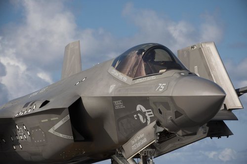
Which was then significantly redesigned for the F-35 (and which required some effort to get right)

Navy_pilot_taxis_in_an_F-35C_Lightning_II_carrier_variant,_on_the_flight_deck_of_the_USS_Georg...jpg

The Lockheed design appears to eliminate boundary air using DSI bump alone.
 
Last edited:
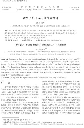
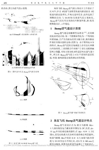
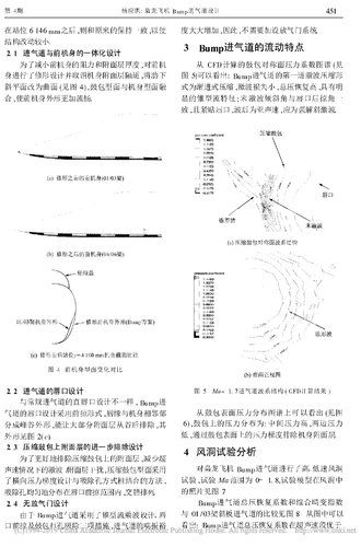
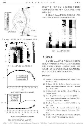
So, now we come to China. The first DSI intake design was seen publicly on the FC-17/FC-1 in 2006. It's possible this was used as a prototype for the future J-20 intake design. The full story is presumably here in this article by a Chengdu engineer:

Design of Bump inlet of thunder/JF-17 aircraft (if anyone can obtain a copy, please send to me!)

NQQNe.jpg

Interestingly, it includes perforated sections which look like they are for boundary air removal on the intake bump area. The vents on the top of the intake cowl might be for getting rid of boundary air from inside the intake.

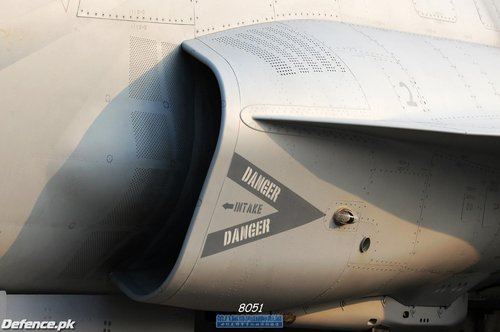
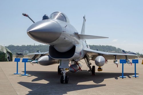
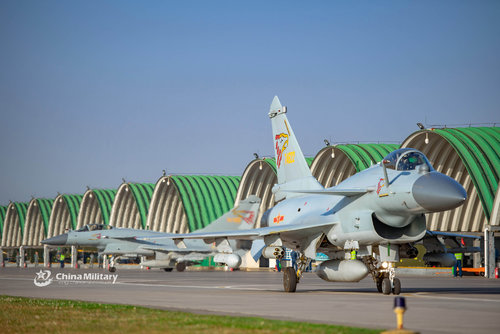
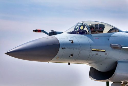
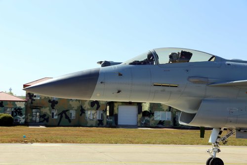
The next DSI design was the J-10B (December 2008?) which is very similar in design to the F-16 DSI. I've not been able to find enough good closeups of the intake to determine if it has the boundary layer removal holes.

J-10B.jpg

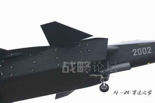
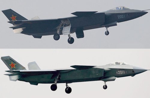
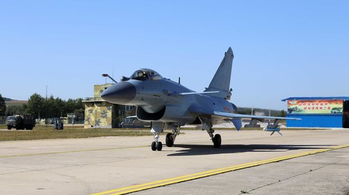
Then, the J-20 prototypes, 2001 and 2002 in 2011

j-20-no-2002-test-flight-on-january-21-3.jpg


This appears to have no boundary layer removal devices except the DSI bump. This intake was clearly not working as well as expected, as the design was altered significantly from 2011, first flight in 2014.

j20_2011_01.jpg

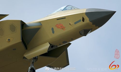
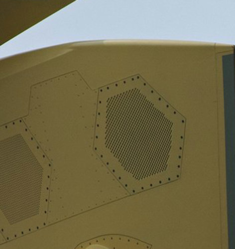
Closeups of the revised intake are available. Notably, there are what look like perforated sections on the intake cowl which might be related to boundary air removal, or possibly auxiliary air intakes. If so, it is hard not to assume this was a fix for a problem rather than something intended.

DjbJ1C7UYAEL-mT.jpg

grilles-or-aerials.jpg
 
Last edited:
It's basically got the same design as the J-20, but I didn't include it as I was really looking at Chengdu's DSI progression. If you have nice pics depicting the intakes on the first and second prototype, by all means post away :)
 
is the intake on the f8u3 Corsair a not-as-hard-to-design variant of DSi, though? being so close to the nose, the air doesn't travel very far while compressed, so maybe the compression isn't as significant?

could it be then that the boundary layer on f8u3 isn't that much different from boundary layer going into mig-21 intake, for example?

Yes, it's probably easier to get acceptable boundary layer removal results with the forward intake position, and this might be a reason for its location. The forward fuselage was carefully profiled as a compression bump however - when Vought studied enlarged radar antennas, they looked at moving the radar backwards to avoid altering the nose shape.
 
The Crusader III intake does operate in favourable conditions because there is very little airframe surface ahead of the intake on which a viscous boundary layer could grow. However the compression due to the intake shock system is comparable to other intake types (including the MiG-21), as in any case the air must be slowed down from (near) free stream Mach to subsonic downstream of the throat. This process is also the worst offender when it comes to causing BL growth, so the benefit from placing the intake at the tip of the nose isn't all that big in the end. In fact, like the F11F-1F and JF-17 both the MiG-21 and Crusader III intakes have a BL bleed at the throat (a ring of perforations round the centre body in the MiG, a slot in the F8U3).
 
The Crusader III inlet does operate in less challenging conditions because there is very little airframe surface ahead of the intake on which a viscous boundary layer could grow. However the compression due to the intake shock system is comparable to other intake types (including the MiG-21), in any case the air must be slowed down from (near) free stream Mach to subsonic downstream of the throat. This process is also the worst offender when it comes to causing BL growth, so the benefit from placing the intake at the tip of the nose isn't all that big in the end. In fact, like the F11F-1F and JF-17 both the MiG-21 and Crusader III intakes have a BL bleed at the throat (a ring of perforations round the centre body in the MiG, a slot in the F8U3).

The BL exit can be seen just slightly aft of the corner of the intake.
Chance-Vought-XF8U-3-Crusader-III.jpg
 
Spill doors. Basically, the size of your intake opening is subject to two conflicting requirements, on the one hand it must be large enough to supply enough air mass flow to the engine at low air speed, but on the other hand not so big as to cause lots of drag from spillage in the supersonic regime. There are various ways to get an acceptable compromise, depending on what exactly your requirements are. For example, if you do not need high efficiency at supersonic speed (dash only at moderate Mach), you can simply take the penalty and go with a relatively large fixed intake area as in the F-16. If you need good performance at appreciably more than Mach 1.8 or extended supercruise, some kind of variability is pretty much inevitable. Either variable capture area (F-15) that can adapt to the flight regime, auxiliary inlets (Su-27) to supplement a small main intake opening at low speed or spill doors (F8U3) to reduce the drag penalty from supersonic spillage round the lip of a large intake.

Spill doors is incidentally another possible reason for those apertures on the J-20 (it'd be in good company - the F-22 has spill doors on the spine!), although they seem a bit small to me for that purpose.
 
Last edited:
Don't forget that spilled air comes from point at higher pressure in the stream (convergent then divergent), increasing exit velocity, hence energizing the boundary layer.
This decrease drag inside the inlet and increase favorable pressure gradient where needed ("coanda effect").
As written years ago, when trace of this appeared on the early pictures, the double spill air outlet on the J-20 help positioning the shock wave for efficient compression at both regime (sub and sup).
 
Here's a wind tunnel & CFD comparison of the DSI and conventional fixed ramp intake on early JF-17 prototypes, unfortunately in Chinese:


And an article dealing with the BL bleed system:


(The paper referenced in the abstract is available here in full: https://www.semanticscholar.org/pap...asud/6149e7a1c63808954c08c1eb8edd2bf11e37b328)
 
Don't forget that spilled air comes from point at higher pressure in the stream (convergent then divergent), increasing exit velocity, hence energizing the boundary layer.
This decrease drag inside the inlet and increase favorable pressure gradient where needed ("coanda effect").
As written years ago, when trace of this appeared on the early pictures, the double spill air outlet on the J-20 help positioning the shock wave for efficient compression at both regime (sub and sup).
Those grills on the J-20 look pretty far forward to be spill outlets. Those are typically further downstream.
 
The DSI intake is not new.

A DSI or diverterless supersonic intake is a fixed geometry intake which incorporates a 3D "bump" in front of the intake which diverts sluggish boundary air away from the intake. Here's the F-35 DSI showing how it works.

View attachment 619725


Despite what Lockheed might tell you, it's not something they invented in the 1990s. NASA research on intake design in the mid 1950s included Antonio Ferri's compression bump with forward swept scoop or "Ferri"intake.

View attachment 619723
An object of this invention is to provide a novel construction of a scoop-type supersonic air inlet for the efficient conversion of dynamic pressure to static pressure. A further object of this invention is to provide a novel construction to facilitate starting of a Scoop-type Supersonic air inlet. Increases in static pressure, or compression, in a supersonic inlet can be accomplished by the physical turning of the air which results in the generation of compressive shock waves. A further object of the invention comprises the provision of a scoop-type air inlet having a novel aerodynamic compression surface (hereinafter termed a compression bump) for more efficiently producing compression in the inlet. In accordance with the invention, the compression bump is formed on the inlet surface adjacent to the aircraft body member from which the inlet projects so that only a part of the physical turning and resulting air compression required is produced by the inlet outer wall formed by the scoop, the rest of the required physical turning and resulting air compression being effected by the bump surface. The compression bump preferably is integral with the surface of said aircraft body member and its upstream end may be disposed upstream or downstream of the leading edge of said outer wall of the inlet. With the leading edge of said bump disposed upstream of the leading edge of said inlet outer wall, the presence of the bump also provides precompression of the air before the air enters the inlet thereby reducing the Mach number of the supersonic airstream before the air enters the inlet so that less air spillage is required to start the inlet. In addition, in the case of a three-dimensional bump, the bump imparts to the air flow a pressure gradient which is normal to the direction of the entering air thereby assisting in removal of the boundary layer of air adjacent to said body member and bump.


A somewhat related design of intake was used on the Grumman F-11F-1. However, the F-11F-1 bump was small and did not remove the boundary layer sufficiently - it required a porous surface behind the bump to remove boundary air.
View attachment 619724

The F8U3 used a proper "Ferri" type intake design - the "compression bump" was formed by the underside of the nose, and the intake cowl swept forward very much as in the Ferri patent. It was able to reach Mach 2.2, limited by engines but not the fixed geometry intake.

View attachment 619726

However after the 1950s, the complex fully variable intake became ''de rigueur'' in fighter design and the Ferri intake was largely forgotten, though not by Vought. In 1971-72 Vought designed a lightweight fighter, the V-1100, for the LWF competition which used a version of the Ferri intake for light weight and decent performance.

View attachment 619727View attachment 619728

General Dynamics studied a Ferri intake for their Model 401 LWF but ended up going for a fixed pitot intake with a splitter plate instead on what became the F-16.

In the early/mid 1990s Lockheed (now including General Dynamics) did an extensive study on intakes and found that new CFD (computational fluid dynamics) analysis could model and predict air flows with much greater precision, allowing the fixed Ferri type intake to be more efficient, to the point it could match a more traditional intake design while being 30% lighter, and with benefits in terms of stealth.

They first tested it on an F-16:

View attachment 619729

Then used it on the X-35

View attachment 619732

Which was then significantly redesigned for the F-35 (and which required some effort to get right)

View attachment 619733

The Lockheed design appears to eliminate boundary air using DSI bump alone.
thank you your analysis is great, I learned something, this is avery nice post ans really I am glad to see smart analysis, congratulations and thank you very much
 
So, now we come to China. The first DSI intake design was seen publicly on the FC-17/FC-1 in 2006. It's possible this was used as a prototype for the future J-20 intake design. The full story is presumably here in this article by a Chengdu engineer:

Design of Bump inlet of thunder/JF-17 aircraft (if anyone can obtain a copy, please send to me!)

View attachment 619771

Interestingly, it includes perforated sections which look like they are for boundary air removal on the intake bump area. The vents on the top of the intake cowl might be for getting rid of boundary air from inside the intake.

The next DSI design was the J-10B (December 2008?) which is very similar in design to the F-16 DSI. I've not been able to find enough good closeups of the intake to determine if it has the boundary layer removal holes.

View attachment 619772

Then, the J-20 prototypes, 2001 and 2002 in 2011

View attachment 619773


This appears to have no boundary layer removal devices except the DSI bump. This intake was clearly not working as well as expected, as the design was altered significantly from 2011, first flight in 2014.

View attachment 619774

Closeups of the revised intake are available. Notably, there are what look like perforated sections on the intake cowl which might be related to boundary air removal, or possibly auxiliary air intakes. If so, it is hard not to assume this was a fix for a problem rather than something intended.

View attachment 619775

View attachment 619779
man you really are very smart i loved your analysis really you enlighten me up, really thanks, you have one of the best analysis i have seen cool and smart
 
Here's a wind tunnel & CFD comparison of the DSI and conventional fixed ramp intake on early JF-17 prototypes, unfortunately in Chinese:


And an article dealing with the BL bleed system:


(The paper referenced in the abstract is available here in full: https://www.semanticscholar.org/pap...asud/6149e7a1c63808954c08c1eb8edd2bf11e37b328)
what i found interesting is the F-35 does not have such system, in my humble opinion the Bump on J-20 is huge, resulting in very high drag, on JF-17 the bump is relatively small similar to the one fitted to the F-11F-1 that overscan has posted of the ferri type intake, i think very likely the chinese engineers tried to reduce the bump size thus they needed those porous holes for the bleeding system
 
Interestingly the article referenced above by Pakistan-based researchers seems to say the passive bleed system on the JF17 intake actually doesn't improve things overall and was a bad idea.

I read the article in detail and it seems more theoretical. However note that the Block III JF-17 will have a revised (and enlarged) intake.
 
Last edited:
A higher operating Mach number requires a steeper bump which will be longer and so has more time for the boundary layer to grow, hence bleed to remove this. Lots of impact from how fast you want to go.
 
Volume 39, Issue 4
August 2007 Nanjing Air and Sky University
Journal of Nanjing University of Aeronautics & Astronautics Vol. 39 No. 4 Aug . 2007
Xiaolong Aircraft Bump Inlet Design
Yang Yingkai 1, 2
( 1. School of Energy and Power, Nanjing University of Aeronautics and Astronautics, Nanjing 210016, China; 2. Chengdu Aircraft Design Institute, Chengdu, 610041)

Abstract: The design and wind tunnel test of the advanced non-channel supersonic inlet (Bump) of the Xiaolong aircraft were analyzed. The results show: Xiaolong Aircraft Bump
The performance of the inlet is excellent, the total pressure recovery coefficient is high, and the ratio of the inlet to the swash plate is increased by 0. 02 to 0. 04; the comprehensive distortion index is low, and the requirements for the matching of the entry/exit are satisfied;
And the boundary layer barrier and the venting door system are eliminated, which makes the aircraft less resistant, lighter in weight and more reliable.
Key words: Bump inlet; total pressure recovery coefficient; comprehensive distortion index; in/out matching
CLC number: V 211. 3 Document code: A Article ID: 1005-2615( 2007) 04-0449-04
Received date: 2006-02-19; Revision date: 2006-04-29
About the author: Yang Yingkai, male, doctoral student, researcher, born in September 1964, E-mail: boatman7671@126.com.

Design of Bump Inlet of Thunder /JF-17 Aircraft

Yang Yingkai 1, 2
(1. College of Energy and Power Engineering , Nanjing University of Aeronautics & Astronautics, Nanjing , 210016, China; 2. Chengdu Aircraft Design and Research Institute , Chengdu, 610041, China)
Abstract: An advanced diverterless supersonic inlet (bump) design and the wind tunnel test of the Thunder / JF-17 aircraft are analyzed. The bump inlet has excellent aerodynamic performances: high total pressure recovery (eis 0. 02~ 0. 04 higher than traditional fixed geometry inlet) , low distortation and good compatibility. The Bump inlet eliminates many traditional complex features associated with boundary layer Manageement: the diverter, bleed system and bypass system. By eliminating these features, the inlet aperture is integrated with the aircraft forebody, thus producing the best value configuration with low Drag , low weight and high reliability.

Key words: bump inlet; total pressure recovery; distortation; inlet-engine matching

Introduction


Inlet design is one of the keys to fighter design because Increased airway total pressure recovery factor by 1%, which can increase engine thrust 1. 3% to 1. 5% [1];
Safety; in addition, the inlet is also the three strong scattering sources for the forward direction of the aircraft. One of them accounts for 30% to 50% of the RCS (forward) of the aircraft. therefore, Countries pay great attention to the design of the inlet.

Lockheed Martin of the United States opened in early 1990 Start exploring a new alternative to traditional supersonic inlet design Methods [2-4], the most promising design concepts in their research Yes: “No Boundary Channel Supersonic Intake (Bump)”, it cancels Now most of the supersonic fighter inlets must not be designed. Less enclosing floor, venting system and bypass system, making the aircraft Ending in terms of performance, mobility, stealth, structure and quality nice. After more than a decade of hard work, Lockheed Martin’s The design technology has matured and successfully used F-16 fighters.

Based on the flight test verification (see Figure 1(a)), this design technique is adopted. The technique was used on the F-35 aircraft (see Figure 1(b)).

The Xiaolong aircraft is a single-engine light fighter, on 01 / 03 aircraft into the air passage is a sloping plate inlet scheme for the lower ribs on both sides, and the pipes on both sides converging in the fuselage, connected to the engine through a straight section, intake. The layout of the road is somewhat similar to that of the F-35. To further mention Supersonic performance of high aircraft, 04 / 06 aircraft inlet scheme completed on both sides of the ribbed Bump inlet scheme, station 6 146 mm

The following pipes are the same as the original to minimize structural aspects

The modification, Figure 2 is a schematic diagram of the inlet.

Figure 1 Application of Bump inlet on foreign fighters

Figure 2 Xiaolong Aircraft 04 / 06 Bump Inlet


The design of the Bump inlet scheme of the Xiaolong aircraft was carried out.

In the past two years, after 4 rounds of inlet model high-speed wind tunnel test and 1 round Low-speed wind tunnel test research, continuous improvement and improvement, and finally reached Intended purpose: Compared to the 01 / 03 conventional inlet scheme Bump inlet has higher total pressure recovery performance, in/out Good performance and stable work.

1 Bump inlet design principle

Bump inlet is based on cone flow theory [5-7], using multiplication Wave machine principle design. Convert a cone into an equivalent Compressing the surface, the resulting flow field is still a conical flow, a cone shock Attached to the edge of the compressed surface (see Figure 3). Due to the cone flow itself Characteristics, there are normal and horizontal on the compressed surface of the Bump inlet To the pressure gradient, the combined effect of the two is equivalent to the presence of a passive surface Layer blowing device that blows most of the fuselage cover layer out of the intake port. In addition, there is no boundary layer on the Bump inlet.

Good performance can also be obtained by means of blowing and blowing/puffing measures.

Figure 3 Buff inlet "passing wave" principle configuration

2 Xiaolong Aircraft Bump Inlet Design Features

The Bump inlet design points are: Maximum Mach number Ma=1. 7, pre-compression drum package equivalent compression half cone angle is 20 °, height H = 11 km and determine the capture area; in Ma = 0.8 to 1.2

Within the circumference, the throat area is determined according to the flow rate at the maximum state of the engine. The Mach number of the throat is controlled at 0. 6~0. 7; 04 aircraft inner tube The road is also different from the 01 / 03 frame, for the station 6 146 mm The front compression body, lip cover and inner pipe profile were redesigned;
After the station is 6 146 mm, it is consistent with the original, so that The structural changes are small.

2.1 Integrated design of intake port and front fuselage

In order to reduce the resistance of the front fuselage and the thickness of the boundary layer, the front machine The body has been modified and the fuselage layer is removed. The inclined plane is changed to the curved surface (see Figure 4), and the bulge profile is combined with the fuselage profile. Combined, the front fuselage shape is smoother.

Figure 4 Comparison of front fuselage profile changes

2. 2 lip design of the inlet

Unlike the straight lip design of the conventional air intake, Bump The lip of the airway is designed in a forward swept form with the lip adjacent to the fuselage Divided into peaks and valleys, which allows most of the boundary layer to be removed from the valley. The shape is shown in Figure 2(c).

2. 3 further exclusion design of the surface layer on the compression drum pack

In order to better eliminate the boundary layer on the compression bulge, reduce the super Shock/surface interference at the speed of sound, compression bulge profile a method of combining a lateral pressure gradient design with a suction hole method, The suction holes are evenly distributed in the forward swept range of the lips, staggered.

2. 4 no venting door design

Because the Bump inlet uses a cone-shaped flow-passing design, the lip Three measures of mouth plucking and bulging and punching, and the surge of the intake port The degree is greatly increased, so there is no need to add a venting system.

3 Bump inlet flow characteristics

Drum symmetry plane pressure coefficient map calculated from CFD (see Figure 5) It can be seen that: the first shock compression shape of the Bump inlet The formula is progressive compression, the shock loss is small, and the total pressure is restored. Explicit cone flow characteristics; end shock angle and lip sweep angle To, and close to the lip, the wave is subsonic, should be a strong solution to the oblique shock.

Figure 5 Ma = 1. 7 inlet wave system structure (CFD calculation results)

Can be seen from the surface pressure distribution map of the bulge (see figure 6), the pressure distribution on the bulge is: high intermediate pressure, pressure on both sides Low, the fuselage boundary layer is removed by the pressure gradient on the surface of the bulge.

4 Wind tunnel test analysis

High and low speed wind tunnels were carried out on the Bump inlet of the Xiaolong aircraft Test, test Ma range 0 to 1. 8, test model in the wind tunnel The photo is shown in Figure 7.

Bump inlet total pressure recovery coefficient and comprehensive distortion index

A comparison with the 01 / 03 swash plate inlet is shown in Figure 8. From the picture It can be seen that the total pressure recovery coefficient of the Bump inlet is superior to the supersonic speed section.

Figure 6 Ma = 1. 7 compression drum surface pressure distribution (CFD calculation results)

Figure 7 Bump inlet in high speed wind tunnel test

Figure 8 Inlet performance changes with flight Ma


Inclined plate inlet, e increased from 0. 02 to 0. 04, its comprehensive distortion index At the same level as the swash plate inlet, much lower than the engine distortion Limit requirements.

Figure 9 shows the Bump inlet oil flow test results, from the figure It can be seen that most of the fuselage boundary layer is discharged outside the outlet.

Figure 9 Bump inlet oil flow diagram

5 Conclusion
a
The design of the Bump inlet of the Xiaolong aircraft has reached the expected level. Purpose, the results of the wind tunnel test show: the performance of the Bump inlet Excellent, the total pressure of the inlet is restored high, compared with the swash plate inlet, e High 0. 02~ 0. 04; low comprehensive distortion index, good matching performance Well, work is stable and meets the requirements of aircraft and engines.

references:
[1 ] Seddon J. Intake aerodynamics [ R ]. AIAA Education Series, 1985.

[2] Mcfarlan J D III . Lockheed Martin’ s joint strike Fighter diverterless supersonic inlet [ M ]. National Press Club, 2000.

[3] Yang Yingkai, Li Yuxi. A JSF X-35 [J]. International aviation, 2001(8): 13-15.

[4 ] Hehs E. JSF diverterless supersonic inlet [ EB/OL ]. http: //www .codeonemagazine.com/archives/2000/Articles/july-00/divertless-1.html.

[5 ] Roe P L. Theory of waverider[C]//AGARD-LS-42, 1972: 1-17.

[6 ] Yang Yingkai. The research of bump inlet design [C] // Russian-Chinese Scientific Conference, 2003: 9-12.

[7] Liang Dewang, Li Bo. Anti-design of the air inlet without a passage and the surface layer removal machine Analysis [J]. Acta Aeronautica Sinica, 2005, 26(3): 286-289.
 

Attachments

  • 枭龙飞机Bump进气道设计_杨应凯.pdf
    319 KB · Views: 54
  • 枭龙飞机Bump进气道设计_杨应凯_Page_1.jpg
    枭龙飞机Bump进气道设计_杨应凯_Page_1.jpg
    864 KB · Views: 83
  • 枭龙飞机Bump进气道设计_杨应凯_Page_2.jpg
    枭龙飞机Bump进气道设计_杨应凯_Page_2.jpg
    735.8 KB · Views: 87
  • 枭龙飞机Bump进气道设计_杨应凯_Page_3.jpg
    枭龙飞机Bump进气道设计_杨应凯_Page_3.jpg
    739 KB · Views: 79
  • 枭龙飞机Bump进气道设计_杨应凯_Page_4.jpg
    枭龙飞机Bump进气道设计_杨应凯_Page_4.jpg
    746.7 KB · Views: 86
Last edited:
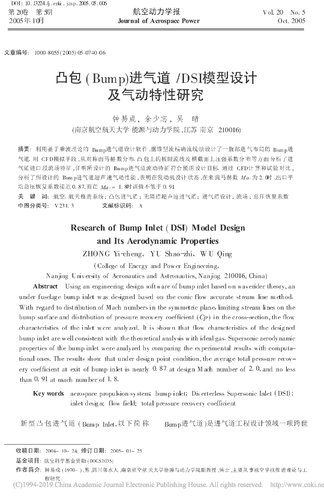
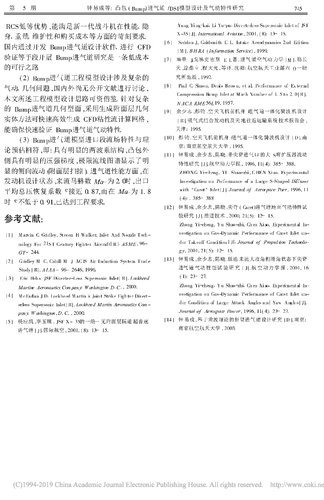
And here's an article on the J-10B intake.

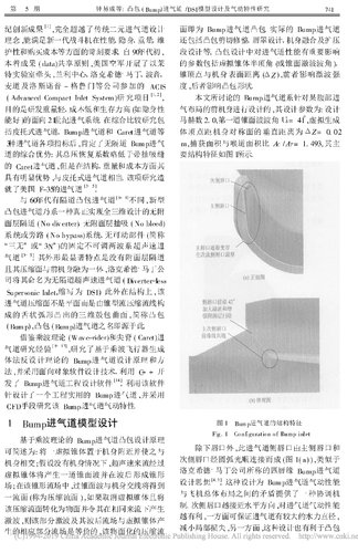
Bump inlet / DSI model design And aerodynamic characteristics

Volume 20 Number 5 October 2005 Journal of Aeronautical Power
Received date: 2004- 10- 24; Last revision date: 2005- 01- 25
Fund Project: Funded by Aviation Science Foundation (00C52035)
About the author: Zhong Yicheng (1970- ), male, Sichuan Linshui, associate professor of the School of Energy and Power, Nanjing University of Aeronautics and Astronautics, Ph.D., mainly engaged in aerospace propulsion theory and work Cheng research.
Article ID: 1000-8055( 2005) 05-0740-06
Zhong Yicheng, Yu Shaozhi, Wu Qing

(School of Energy and Power, Nanjing University of Aeronautics and Astronautics, Nanjing 210016, China)

Abstract: Using an engineering design sof tware of bump inlet based o n waverider theory, an Under fuselage bump inlet w as designed based on the conic f low accurate st ream line method.
With regard to dist ribution of Mach numbers in the symmet ric plane, limiting stream lines on the
Bump surface and distribution of pressure recov ery coef ficient (Cp ) in the cross-section, the flow
Characteristics of the inlet w ere analy zed. It is show n that flow characteristics of the designed Bump inlet are are w ell consistent with the theoretical analysis with ideal gas. Supersonic aerodynamic Properties of the bump inlet were analyzed by comparing the experimental results with computational Ones. The results show that under design point condition, the average total pressure recovery Coefficient at exit of bump inlet is is nearly 0. 87 at design Mach number of 2. 0, and no less Than 0. 91 at mach number of 1. 8.

Key words: aerospace propulsion sy stem; bump inlet; Div erterless Supersonic Inlet ( DSI) ; Inlet design; low field; total pressure recovery coefficient

The new Bump Inlet (hereinafter referred to as Bump Inlet) is a cross-border in the field of inlet engineering design.

DOI : 10. 13224 /j . cnki . jasp. 2005. 05. 006

Innovative achievements [1], completely surpassing the traditional binary inlet design The concept can meet the performance, stealth, weight and dimension of the new generation fighter Demanding requirements in terms of care and purchase costs. Since the early 1990s, In line with the principle of data sharing, the US Air Force launched Leading the lab, Langley Center, Lockheed Martin, Boeing, ACIS and other companies such as Nothrop-Grumman (Advanced Compact Inlet System) research project [1, 2],

The aim is to develop light weight, low cost and high viability (such as stealth) Can be good) for the 21st century intake system. Comprehensive comparative research package
Including Pitot Inlet, Bump Inlet and Caret Inlet After the three types of inlet parameters, it is confirmed that there is no bypass Bump intake. Comprehensive advantages of the road: its total pressure recovery coefficient is slightly lower than with suction Caret inlet, but in terms of structure, weight and cost It has obvious advantages and is comparable to the Pitot inlet. The research
It is the inlet of the US F-35

Different from the channel convex inlet channel [6-8] in the 1960s, new type The convex hull inlet is a kind of true full three-dimensional design. No diverter, no bleed System or bypass system, no moving parts (referred to as "Three no" or "3N" fixed non-adjustable two-wave system Airway [3 ~ 5]. The most striking feature of its shape is that there is no boundary layer. And its compression surface is integrated with the front fuselage, Lockheed Martin The company named it a non-channel supersonic inlet (Diverter-less Supersonic Inlet, abbreviated as DSI). Also structurally, The inlet compression surface is not a flat surface but a conical flow compression streamline a three-dimensional bulge surface that protrudes from a tongue-shaped arc, referred to as a convex hull (Bump), the name of the Bump inlet is derived from this.

Learn from Wave-rider and Caret Airway research experience [9~13], studied based on multiplier aircraft generation Bump inlet design principle and method of body-anti-design theory
Law, and adopt object-oriented software design technology, using C + + to open Bump inlet engineering design software [14] was issued. Use the software The needle is designed with a practical and practical Bump inlet and adopted CFD means to study the aerodynamic characteristics of the Bump inlet.

1 Bump inlet model design

Design principle of Bump inlet convex hull based on wave theory It can be briefly described as: placing a virtual cone near the fuselage and making it The fuselage intersects; assuming that there is no fuselage, the supersonic flow flows through The virtual cone will produce a cone wave and form a cone behind the wave Field; in the conical flow field, the cross-cone surface wave and the fuselage intersection line will be obtained First-class face (called compressed flow face), if the virtual cone is canceled and will The compressed flow surface is converted into a surface and is produced under the same flow Shock wave, the part of the shock wave and its post-wave flow field and virtual cone production The corresponding partial flow field is equivalent, the surfaced compressed flow

The surface is the Bump inlet convex hull. Actual Bump inlet Also includes convex hull shear trimming, lip design, fuselage fusion and diffuser Segment design, etc. Convex design has an important impact on inlet performance The parameters include the virtual cone half apex angle (or cone shock wave angle), The distance between the cone apex and the surface of the fuselage (ΔZ), the former affects the shock wave Degree, the latter affects the shape of the convex hull. The Bump inlet system discussed in this article is for a certain abdomen. The front fuselage of the gas layout is designed with the following design parameters:

Mach number 2. 0, the first cone surface wave angle US = 41 °, virtual generation The vertical distance of the vertices from the plane of symmetry of the fuselage is ΔZ = 0. 02m, capture area and throat area ratio AC / AT = 1. 493, its main The structural features are shown in Figure 1.

Fig.1 Configuration of Bump inlet

In addition to the lower lip, this air inlet side lip consists of the main side lip and The secondary lip is smoothly connected by a circular arc (Fig. 1(a)), similar to Lockheed Martin called the four lip Bump inlet

Design ideas [4, 5]. This design is a Bump inlet aerodynamic performance The contradiction with the overall layout of the aircraft provides a coordination machine system. The closer the secondary lip is to the horizontal direction, the aerodynamic performance of the inlet The more favorable, on the one hand, the larger the hydraulic diameter of the inlet is ensured. Reduce local losses, on the other hand, this design is also conducive to convex hull The upper low-energy boundary layer is swept out from the secondary lip. But if it If the angle between the horizontal line and the horizontal line is too small, the angle between the body and the outer lip will be Reduced, integrated design of the air intake of the fuselage (especially stealth Can) be unfavorable. The front view of the inlet port of this article is the last side lip and horizontal The angle is 45°.

Viewed from the side view (Fig. 1(b)), the main and secondary lips are opposite the fuselage Both are swept forward by 42°, so the two are collinear in this view, which guarantees The cover layer is effectively swept. The lips on both sides are collinear in side view, at The front view is a two-phase line. This design draws on the F16. Bump inlet verification machine design ideas [4]. Another of this model A typical feature is that the lip is of variable thickness: the thickness of the lower lip is R 5, the thickness of the main side lip increases from R 5 to R 10 , the secondary lip The thickness is R 10 .

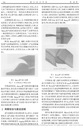
Figure 2 shows the three views of the Bump inlet, which is clear from the figure. See the shape of the convex surface of the convex hull. Secondary lip/convex compression surface Based on the intersection point, the designed convex hull compression surface height ratio is about 1 0. 337 (maximum height), aspect ratio is 1. 1. 078 3 (whole width)
degree).

Fig. 2 A rendering of Bump inlet

It should be noted that the position of the Bump inlet throat is cut.
The surface is very complicated, so design the section to the inlet of the inlet
In the subsonic speed expansion section, it is necessary to comprehensively consider the cross-sectional shape transition.
(from irregular to regular shape), cross-sectional area gradation, longitudinal smoothing
Three issues such as transition. Bump inlet engineering design software implementation
The subsonic speed expansion section automatically generates the function, so the inlet of this paper
The model system includes the front fuselage, the inlet section of the inlet and the subsonic diffuser
The complete engineering model, including the segment.


2 meshing and algorithm description

The inlet model calculation area is shown in Figure 3(a), which includes Front fuselage, inlet section of the inlet and outer fuselage, the last section of the inlet a sufficiently long fuselage, air intake subsonic diffuser, etc. External flow field. Computational grid is divided by Gambit software, the main To calculate for supersonic flow, so its body mesh is overall Seen to be tapered, see Figure 3(a). The far (outer) field flow area is about the diameter For the maximum diameter of the fuselage 3.5 times, to reduce the calculation grid, from the object Radial mesh when the surface boundary layer mesh begins to map to the far field boundary

The size is increased layer by layer according to the scale factor of 1.2. For more complicated lips / convex hull / fuselage joint front and rear area grid, using completely non-knot Construct a grid, see Figure 3(b). Finally generate Bump inlet grid points The number is 274 674 and the number of units is 386 078.

Fig. 3 Surface grid of Bump Inlet

Calculate the endogenous domain near all solid walls in the front fuselage/intake 10 layer viscosity with a scale factor of 1.35 and a thickness of 30 mm grid. Direct application in terms of the structural complexity of the Bump inlet Gambit is unable to generate this kind of sticky mesh, and engineering design The software can construct the boundary layer thin along the solid wall according to the user's needs.

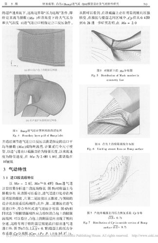
The shell entity, which in turn reliably generates the boundary layer mesh. Proof of practice This method is effective and can guarantee the portability of the design. Can make a quick assessment. Figure 4 shows the thinness of the inlet port model at different positions. The shell entity and its boundary layer mesh. Figure 4 (a) is at the lip C-type boundary layer grid, Figure 4 (b) is the inner channel calculation area, internal communication The calculation domain in the boundary layer is the structural grid, and the remaining calculation domains are subject to
Structure grid.
Model calculations were done using the commercial software Fluent, iterating over The second-order implicit solution is used in the process, and the CFL is selected under normal circumstances. The number is 30. This calculation selects the RNG k-X turbulence model for 湍. The flow is numerically simulated and the near-wall treatment is performed using the non-equilibrium wall function method.

In terms of boundary condition setting, the wall surface has no slip condition. In this article The supersonic velocity comes down, and the far-field boundary takes the "pressure far-field" condition, ie Given the incoming Mach number (Ma∞) and the atmospheric pressure at that height And atmospheric temperature. The inlet of the inlet port specifies the outlet back pressure condition.

Fig . 4 Boundary layer grid of Bump inlet

And by adjusting the inlet pressure of the inlet to meet the specified outlet level Mean Mach number (Ma2) or physical flow. Calculation using full size mode Type, with the inlet outlet section diameter as the characteristic length, since the flow rate Degree is the characteristic speed. When Ma∞ is 2.0 and 1.8, the Reynolds number is 107 orders of magnitude.

3 Aerodynamic characteristics

3. 1 Flow field characteristics of the inlet section Bum inlet with Ma∞ = 2. 0 and Ma2≈ 0. 45

The calculation results analyze the flow field characteristics of the inlet section. Figure 5 shows the symmetry face Hertz distribution. As can be seen from the figure, there are two at the inlet of the inlet. The obvious shock wave, and the second wave is close to the positive shock, with the expected The design state wave system is consistent; in addition, the second shock wave is in the intake In addition to the inlet of the road, it conforms to the original intention of the external pressure inlet. Figure 6 is the phase The limit on the convex hull drawn according to the viscous stress of the wall in the same state Streamline diagram. It can be seen that the lateral direction appears in the boundary layer on the convex hull Split speed, which will help sweep the boundary layer low energy flow out of the inlet Imported. Figure 7 is a pressure division on the yoke of ΔX = 0.7 on the convex hull Cloth coefficient Cp distribution map (Cp= ( P- P∞ ) / ( 0. 5d∞ V2∞) ) ,

As can be seen from the figure, there is a significant extension pressure on the section. Gradient, in the region between the shock and the wall, the Cp value decreases from 0.42 To 0. 28. Further research shows that at Ma∞ = 2. 0

Fig. 5 Distribution of Mach number in Symmetry plane

Fig. 6 Limiting flow lines distribution on the bump surfacel


Figure 7 Pressure recovery coefficient Cp distribution on the outer section of the Bump Surface
(ΔX= 0. 7)

Other Ma2 states and Ma2 states of Ma∞ = 1.8 Below, the flow characteristics of the above-mentioned inlet sections are very close.


3. 2 air intake aerodynamic performance

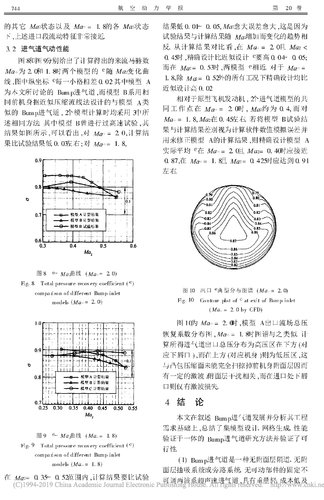
Figure 8 and Figure 9 show the calculated incoming Mach number, respectively. Ma∞ is 2.0 and 1.8. The e of the two models varies with Ma2. 线。 The line, the vertical coordinate e of each figure in the figure is 0. 02. Model A For the Bump inlet discussed in this article, the model B is used for phase Model A with the same front fuselage designed according to the approximate compressed streamline method Like the Bump inlet, the two models are calculated using 3 The same method is described. Model B has been tested at high speed, The results are shown in the figure. It can be seen that for Ma∞ = 2. 0, the knot is calculated. Fruit is lower than the test result by 0.33; for Ma∞= 1. 8

Fig. 8 Total pressure recovery coefficient (e) comparison of different Bump inlet Models (Ma∞= 2. 0)


Fig. 9 Total pressure recovery coefficient (e) Compariso n of different Bump inlet Models (Ma∞= 1. 8)


In the range of Ma2 = 0.35 ~ 0. 52, the calculation results are more than the test The result is 0. 01~ 0. 05, the larger the Ma2, the larger the error, because The test results and the results of the calculations change with the increase of Ma2 anti. From the comparison of the calculation results, at Ma∞ = 2. 0 and Ma2 <至0. 05; The precision design is higher than the approximate design e. 04~ 0. 05; When Ma2=0.53, the two models e are similar. For Ma∞ =1. 8. Accurate design ratio under all conditions except Ma2= 0. 52

Approximate design height is 0.02.

Relative to the prototype aircraft engine, a total of 2 inlet models When the working point is at Ma∞ = 2. 0, Ma2 is about 0.4, and Ma∞ = 1. 8, Ma2 is around 0. 45. If the model B test knot The difference between the result and the calculation result is regarded as the numerical simulation error of the calculation software. Used to correct the calculation result of model A, then accurately design model A The actual average e should be close to Ma∞ = 2. 0 and Ma2 = 0.40. 0. 87, when Ma∞ = 1. 8 and Ma2= 0. 425 should reach 0. 91 about.

Fig. 10 Contour plot of e exit of Bump inlet (Ma∞ = 2. 0) by CFD

Figure 10 shows the total pressure of the model A outlet flow field when Ma∞ = 2. 0 Recovery coefficient distribution map, similar to Ma∞ = 1. 8 when the spectrum is similar. meter Calculate the total pressure distribution at the outlet of the inlet port below the high pressure zone (right Should be the lower lip), while at the top (corresponding to the fuselage) is the low pressure zone, this The convex surface of the convex hull does not completely sweep away the front fuselage boundary layer There is a certain shock/layer interference associated with the lower lip at the entrance The mouth only has a shock loss.

4 Conclusion
This paper describes the development of Bump inlet and analyzes its engineering. Based on the requirements, summarize the model design, grid generation, performance Validated in one of the Bump inlet research methods and verified Line.

(1) Bump inlet is a non-adhesive layer, no attachment Surface suction system or bypass system, no moving parts are fixed Adjustable two-wave supersonic inlet with light weight and low cost RCS has lower advantages and can meet the performance and hiddenness of the new generation fighters Demanding requirements in terms of body, weight, maintainability and purchase cost.

Domestically develop Bump inlet design software and conduct CFDVerification and other means to carry out Bump inlet research is a low cost The feasible way.

(2) Bump inlet engineering model design involves complex Pneumatic and geometric problems, there is no open literature for discussion at home and abroad. The engineering model design ideas described in this paper can be used for reference. For complex Bump inlet geometry, using the boundary layer geometry The solid method can quickly and efficiently generate a CFD viscous flow calculation grid. It ensures fast verification of the aerodynamic characteristics of the Bump inlet.

(3) Flow field characteristics and rationality of the inlet section of Bump inlet model On the prediction, that is: has an obvious two-wave structure, outside the convex hull The side has a distinct pressure gradient, and the limit streamline map shows Significant lateral flow (with surface sweep). Inlet performance, in Engine design state, the flow Mach number Ma∞ is 2.0, the exit The average total pressure recovery coefficient e is close to 0.87, and in Ma∞ is 1. 8 When e is not less than 0.91, the engineering requirements have been met.

references:

[1] Marvin C Gridley, Steven H Walker. Inlet And Nozzle Technology For 21st Century Fighter Aircraft [ R]. ASME , 96-GT- 244.

[2] Gridley M C, Cahill M J. AC IS Air Inducti on System Trade Study [ R] . A I AA - 96- 2646, 1996.

[3] Eric Heh s. JSF Diverter-Less Supersonic Inle [ R] . Lockheed-Martin Aeronautics Company: Washington D.C., 2000.

[4] McFarlan J D. Lockheed Martin 's Joint Strike Fighter Diverterless Supersonic Inlet [ R] . Lockheed Martin Aeronautics Company: Washington , D. C. , 2000.

[5] Yang Yingkai, Li Yuxi. A JSF X-35 – supersonic without a boundary layer Intake [J]. International Aviation, 2001, (8): 13~ 15.

[6] Seddon J, Goldsmith E L. Intake Aerodynamics 2nd Edition [M] . BH RA (Information Service), 1999.

[7] Seiden J, Goldsmith E L. Inlet aerodynamics [M ] . Tian, Tu Dingli, Cheng Daguang, et al. Shenyang: Department of Aerospace Industry Research Institute, 1992.

[8] Paul C Simon, Denis Brown, et al. Performance of External Compression Bump Inlet at Mach Number of 1. 5 t o 2. 0 [R]. N ACA RME 56L19, 1957.

[9] Yu Shaozhi, Peng Yu. Design of the front fuselage/inlet integrated wave machine for aerospace aircraft [ R]. Suction combined engine and world round-trip transportation system technical report meeting, Tianjin: 1995.

[10] Peng Yu. Design of the front fuselage/intake integrated wave machine for aerospace aircraft [D]. South Beijing: Nanjing University of Aeronautics and Astronautics, 1995.

[11] Zhong Yicheng, Yu Shaozhi, Chen Xiao. Flow of large S-bend diffuser with spigot inlet Characteristics study [ J ]. Journal of Aerodynamics, 1996, 11( 4): 385~ 388.

ZHONG Yi-cheng, YU Shao-zhi , CHEN Xi ao. Experimental Investigation on Performance of a Large S-Shaped Diffuser With "Caret " Inlet [ J ]. Journal of Aerospace Power , 1996, 11 (4): . 385~ 388
[12] Zhong Yicheng, Yu Shaozhi, Chen Xiao. Aerodynamic characteristics test of the intake of the Caret inlet Research [J]. Propulsion Technology, 2000, 21(5) : 12~
 

Attachments

  • 凸包_Bump_进气道_DSI模型设计及气动特性研究_钟易成.pdf
    1,002.1 KB · Views: 47
  • 凸包_Bump_进气道_DSI模型设计及气动特性研究_钟易成 (1)_Page_1.jpg
    凸包_Bump_进气道_DSI模型设计及气动特性研究_钟易成 (1)_Page_1.jpg
    648.9 KB · Views: 90
  • 凸包_Bump_进气道_DSI模型设计及气动特性研究_钟易成 (1)_Page_2.jpg
    凸包_Bump_进气道_DSI模型设计及气动特性研究_钟易成 (1)_Page_2.jpg
    1.1 MB · Views: 84
  • 凸包_Bump_进气道_DSI模型设计及气动特性研究_钟易成 (1)_Page_3.jpg
    凸包_Bump_进气道_DSI模型设计及气动特性研究_钟易成 (1)_Page_3.jpg
    1,009.5 KB · Views: 82
  • 凸包_Bump_进气道_DSI模型设计及气动特性研究_钟易成 (1)_Page_4.jpg
    凸包_Bump_进气道_DSI模型设计及气动特性研究_钟易成 (1)_Page_4.jpg
    807.1 KB · Views: 81
  • 凸包_Bump_进气道_DSI模型设计及气动特性研究_钟易成 (1)_Page_5.jpg
    凸包_Bump_进气道_DSI模型设计及气动特性研究_钟易成 (1)_Page_5.jpg
    878.5 KB · Views: 84
  • 凸包_Bump_进气道_DSI模型设计及气动特性研究_钟易成 (1)_Page_6.jpg
    凸包_Bump_进气道_DSI模型设计及气动特性研究_钟易成 (1)_Page_6.jpg
    729.2 KB · Views: 92
Last edited:

Similar threads

Please donate to support the forum.

Back
Top Bottom