And here's an article by researchers in the same university reverse engineering the F-35 DSI inlet from 2005.
Volume 26 Issue 3 Aviation Journal Vo l. 26 No. 3
May 2005 ACTA AERONAUTICA ET ASTRONAUTICA of May 2005
Received date: 2004-03-19; revised date: 2004-07-05
Fund Project: “Five-Year” Air Force Pre-Research Funding Project
Article ID: 1000-6893 (2005) 03-0286-04
Reverse Design of Diverterless Inlet and Mechanism of Diversion of Boundary Layer
Liang Dewang, Li Bo (School of Energy and Power, Nanjing University of Aeronautics and Astronautics, Nanjing 210016, China)
Reverse Design of Diverterless Inlet and Mechanism of Diversion of Boundary Layer
Abstract: The diverterless inlet and forebody of a fighter are constructed by using the Three Dimensional Reversion Technique of Photos and the external and internal flowfields of the inlet and forebody are calculated.
The Mach contours inside and outside the inlet and the pressure distribution on the bump surface are presented. Mechanism of diversion of boundary layer on diverterless supersonic inlet (DSI) is also analyzed. It can be Seen from the results that there is an initial compression angle at the front point of the bump and an isentropic Compression surface after the shock. The investigation shows that the diverterless supersonic inlet or bump inlet Creates a high pressure area o n the bump compression surface which pushes the air in boundary layer away
From the inlet.
Key words: diverterless supersonic inlet (DSI);bump inlet ;integrated design ;computational fluid dynamics
(CFD)
The design of the air intake is one of the keys to fighter design. in When designing, not only must the intake port be considered within the flight envelope The engine provides sufficient air flow and also considers the overall layout Constraints and requirements for integrated design, but also must meet the battle The overall stealth requirements of the bucket machine.
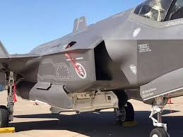
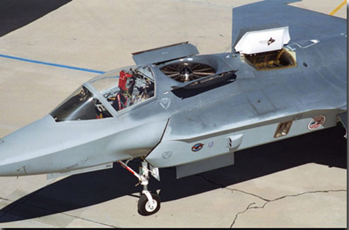
The United States first adopted the "without the surface layer" on the X-35 aircraft. Channel Supersonic Inlet (DSI) design technology, in the intake The port is not provided with a conventional fixed boundary layer compartment, but Counting a three-dimensional curved protrusion (or bulge), this bulge Compress the airflow. This novel design cancels the traditional Complex mechanisms associated with the control of the inlet layer of the inlet, such as the boundary layer The isolation panel, deflation system, and bypass system reduce the weight of the aircraft. This also reduces production and use costs [1 ~ 4].
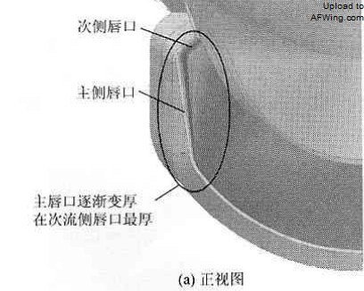
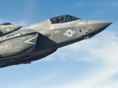
The air intake design of the machine reflects the idea of stealth design. First of all, the inlet pipe is designed to be short S-bend, which can effectively The main radar that shields the engine's fan or compressor blades Wave scattering source. Secondly, the lip of the inlet is designed to be forward-swept. Avoid the formation of angular reflections of radar waves in the lips, and also improve The angle of attack of the inlet. In addition, the inlet layer of the inlet channel Is a large radar wave scattering source, due to the use of no channel Design, greatly improved stealth performance.
However, what kind of configuration is the inlet bulge? How to eliminate it? For the purpose of this, this article uses Nanjing Airlines according to the photo of the aircraft. Aerospace University's "Photo 3D Restoration Technology" restored the aircraft's front The shape of the body and the air intake (including the bulge) was analyzed and used. NAPA software carried out the flow field inside and outside the fuselage/inlet Numerical simulation, the flow characteristics are given, and the drum package exclusion is analyzed. The mechanism of the surface layer.
1 Restoration of a certain aircraft and air intake
The research object is the front fuselage and air intake of the aircraft, not including The wing, smoothed and simplified the belly. Figure 1 shows The restored air inlet lip angle and fuselage surface mesh Figure, inlet inlet cover is 3 lip structure, inlet installation The angle is - 5°. According to the symmetry, the left half of the aircraft is selected.
Generate a grid, the entire calculation grid has a total of 60 blocks, a total of grid nodes Counting 1,031,556. Due to the lack of in-port profile data, plus No. 3 Liang Dewang et al.: Anti-design of the inlet without the passage and analysis of the removal mechanism of the boundary layer
Fig. 1 Cowl angles and surface mesh on fuselage
The focus of this paper is on the shape of the bulge and the masking machine. Therefore, it is roughly designed based on the shape of the inlet and the surface of the drum. a small section of the shape of the inlet, the length and the length of the cover are the same, At the same time, considering the back pressure of the inlet of the inlet, the pipe is relatively straight. Not designed to be a short S-bend.
2 bulge shape and flow analysis
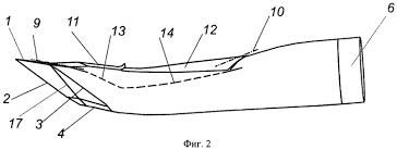
The bulge profile is the key to a non-channel intake. according to The result of the photo restoration is found (Fig. 2), and the drum kit can be shaped according to the shape. Divided into two sections, the first half is similar to a flat conical shape, the second half The section is the transition section and forms part of the duct profile in the inlet.
Fig. 2 Three-dimensional shape of the bump shape
Since the first half of the drum pack acts as a transfer surface layer and forms waves The role of the system, so the focus of this study is on the first half of the drum kit. The profile analysis. Translating and rotating the front half of the drum Then lay it flat in the XOZ plane, from the vertical symmetry plane XOY surface Start, make a cut surface every 5° in the circumferential direction around the X axis. X axis), the intersection of the cut surface and the surface of the bulge is the drum wrapped in different weeks. To the position of the profile, as shown in Figure 3, define the section at Z =0
The position is the basic line position. Then cut the guilloche The wires rotate around the X-axis XOY plane at their respective circumferential angles. The shaped line and the basic line are on the same plane. Next Other types of lines other than this type line circulate around the bulge in the XOY plane (ie, the origin of the coordinates) rotates clockwise, making all the profiles line to the baseline Close together, the results obtained by dimensionless are shown in Figure 4. Compressed in the first half of the flow direction along the apex of the drum kit The face analysis of the face fits the mathematical expression of the bulge profile.
Fig. 3 Slice positions on bump
Fig. 4 Dimensionless slice lines of bump
Its basic line passes through the symmetry plane of the apex of the bulge, at the starting point and water The flat direction is a small angle, approximate to a straight line, the starting angle
Degree θ ≈ 11 °, followed by a concave curve with a small change in angle An upwardly convex curve is leveled at the end profile. In order to analyze the mechanism of the bulge to remove the boundary layer, according to the reverse The calculated bulge line recreates the bulge compression surface, while One spiral body (general cone) is constructed according to the reference line to divide Analysis of comparison. Figure 5 and Figure 6 show the bulge and the spine, respectively.
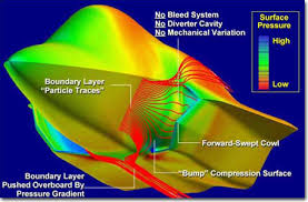
Fig. 5 Surface pressure distribution on bump
Fig. 6 Surface pressure distribution on cone
Surface pressure distribution map. As can be seen from Figure 5, in the head of the drum There is 1 high pressure zone, other areas have lower pressure, and the flow does not have Axisymmetric, so there is a difference in height from the surface of the bulge Such a pressure gradient along the direction of the extension, this pressure distribution can The air flow is pushed to the sides. For the body, there is also a pressure on the head. Higher area, but lower pressure, and this pressure distribution is the axis Symmetrical, the flow is also axisymmetric, flowing along the surface of the spiral body
The circumferential direction is evenly distributed, so there is no effect of migrating airflow. Correct The cone flow (positive cone) we are familiar with, the parameters of the conical surface The distribution is uniform, there is no pressure gradient, so it can't play The role of the transfer surface layer. Analysis believes that it is due to the pressure in the drum The middle height on the shrink surface and the low pressure distribution on both sides make The pressure gradient acts to move the boundary layer to the sides, It acts to eliminate the flow of the boundary layer. Of course, the inlet lip Sweeping is another guarantee that the incoming flow layer does not enter the intake duct.
Key [ 1 , 4] .
3 front fuselage / inlet integrated flow analysis
(1) Calculation conditions Since the boundary layer barrier is removed, the intake air The mouth and the front fuselage of the aircraft become an integrated design, the front of the air intake The velvet bag surface is merged with the front fuselage. Produce a pressure distribution that pushes the boundary layer away from the air inlet, and at the same time To the compression of the airflow. In the mechanism of the DSI inlet In the process of analysis, it is also necessary to adopt an integrated idea to Considering the front fuselage as a whole, analyzing the drum package surface and progress The interaction between the angle and shape of the lip mask.
The specific tactical technical performance requirements for the aircraft are not yet available. Announced, from the information already available, its design flight Mach The number is around 1. 5 or so. Therefore, select 1.5 as the calculated flow horse. Hertz.
(2) Wave system structure Figure 7 and Figure 8 show no attack Angle, no side slip angle, vertical symmetry plane of the aircraft and bulge of the drum The Mach number of the flow field in the horizontal section. As can be seen from Figure 7, The supersonic flow forms a oblique shock wave at the head of the aircraft, and the airflow is in the wave. After decelerating and boosting, and then due to the shape of the fuselage, the airflow Born and expanded, a second oblique shock wave was formed in front of the upper cockpit. The airflow in the rear of the cockpit expands and accelerates. Can be seen from Figure 8. Out, the supersonic flow flows through the oblique shock wave of the aircraft's head, and the airflow is reduced. Speed boost, and then due to the shape of the fuselage, airflow expansion Speed, the Mach number of the airflow before the inlet of the inlet is about 1.44, in the drum The apex of the packet forms a oblique shock wave, the oblique shock wave does not have the upper lip Intersect, but at a certain distance in front of the upper lip, the airflow passes through the first After the oblique shock wave, the deceleration is supercharged in the front of the drum and formed before the inlet.
The second shock wave, the shock angle is larger, and it is close to the surface of the bump Straight, the wavefront Mach number is about 1.2, the wave is the subsonic flow, the whole
Fig. 7 Iso-Mach number contours (symmetric plane, α = 0°)
Fig. 8 Iso-pressure contours on horizontal plane(α= 0°)
The airflow in the air intake is subsonic.
(3) Exclusion of the surface layer due to the inlet bulge with - 5° installation angle, for this purpose also calculates the aircraft's 5° angle of attack The flow field during flight, so that the direction of the flow before the bulge can be basically It is facing the axial direction of the drum kit. Figure 9 shows the flow of the fuselage surface Line and pressure distribution, there is a higher pressure area in the head of the drum bag, Most of the forward flow was pushed to the sides of the drum. Due to the drum kit Close to the import lip on both sides.
 f35-dsi-data (1)-page-008.jpg444.8 KB · Views: 82
 f35-dsi-data (1)-page-009.jpg427.9 KB · Views: 74
 f35-dsi-data (1)-page-010.jpg418.3 KB · Views: 64
 f35-dsi-data (1)-page-011.jpg257.5 KB · Views: 59
 f35-dsi-data (1)-page-005.jpg440.9 KB · Views: 64
 f35-dsi-data (1)-page-006.jpg346.2 KB · Views: 67
 f35-dsi-data (1)-page-007.jpg388.5 KB · Views: 66
 f35-dsi-data (1)-page-001.jpg289.7 KB · Views: 61
 f35-dsi-data (1)-page-002.jpg449.1 KB · Views: 66


