Su-57 Avionics

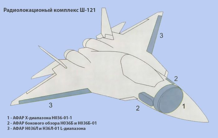
BRLC FH03 radar consists of 4 slot L-band arrays and one X-band slot array in the front. it can search for detection of moving and stationary surface (ground) objects at ranges of up to 250 km. Detects air objects passed 100 kms. I am assuming the L-band arrays on the Su-57 wings are far bigger than the 4 L-band arrays on the helicopter they are talking about.
The L-bands they are talking about sound like they are used for radar surveillance
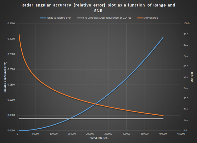
The L-band they state can detect objects camouflaged in the forest or be used as air surveillance, I am assuming the 100km+ is what they are referencing for the L-band and 250kms for the X-band. Maybe the antenna size and power range would put the L-band tracking capabilities to be efficient at 200kms but anything past that as imprecise?
As they described, the L band (decimeter band) is used for SAR (Synthetic Aperture Radar) and early warning
Screenshot 2025-04-04 084810.png

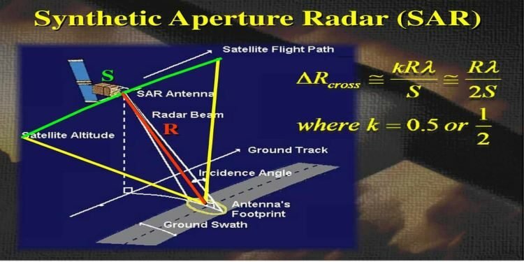
Synthetic Aperture Radar (SAR) is a type of radar used to create highly detailed images of landscapes, structures, or objects, typically from aircraft or satellites. It works by simulating a very large antenna (or "aperture") using the motion of the radar platform to increase resolution far beyond what a physical antenna of the same size could achieve. It doesn't work against air target though since they constantly moving very quickly.
SyntheticApertureRadarSAR-750x375.jpg

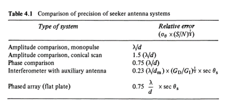
As for the so called early warning against air attack, they probably want to take advantage of the very wide beam of the L band. Because the L band is not used for fire control, so the only thing it need to tell the pilot is if something is incoming at high speed. Probably used to supplement L370 Vitebsk which use UV based missile warning sensor. An UV sensor would be useless against coasting missile, unlike radar based MWS. Assuming the L band length is about 1 meters, with operating wavelength of 30 cm, the beamwidth would be 21 degrees. Which is not very useful at long distance. But if your goal is only warning of missile attack when the missile is like 2 km from your position then you can probably get missile azimuth position accurate to about 700 meters.
 
Last edited:
alright, what is the beamwidth value? can you maybe screenshot the line about beamwidth?
Due to the formatting of the translator and maybe the wording in Russia, it quite hard for me to fully understand what that document trying to say. From the translator, it looks to me like they were listing various requirement about scanning sector, field of regard, output power, sidelobe level ..etc. I can't seem to find anywhere they made a mention of azimuth beamwidth

When I replied, your post didn't have two table, that why I was confused with the value.
So basically 500W peak per T/R module for radar?
Is there any information about their cooling requirement?


So quite similar to most ESA basically.

From 2010 it was 700W with plans to increase the value to 1 kW in 2011/2012. This is some original Russian NPP 'Pulsar' articles about that. I already posted transl versions.

This one is from 2010 :

МОДЕРНИЗАЦИЯ МОЩНОГО МОДУЛЯ БОРТОВОЙ АФАР L-ДИАПАЗОНА

''Модуль первичной разработки был представлен на конференции «Пульсар-2008», сейчас он осваивается в производстве. Вопрос о его модернизации – ответ на требование оперативного повышения уровня эксплуатационных характеристик, что свойственно быстро развивающимся
областям техники.Главная цель модернизации – повышение уровня выходной импульсной мощности с 400 Вт до 700 Вт в рекордной полосе частот 1 -1,5ГГц в каждом из 4-х каналов модуля. При этом габаритные и присоединительные характеристики модуля остаются неизменными.В основе модернизации – новое поколение интегральных сборок под
названием «усилитель мощности» взамен мощных СВЧ транзисторов, а также развитие принципа объемной интеграции. Модернизированный модуль является приемопередающим устройством с коэффициентом шума в заданной полосе не более 4 дБ. Рассмотрен вариант конструктивной модернизации корпуса с целью повышения технологичности сборки, контроля и ремонтоспособности. По параметру удельная выходная импульсная мощность на единицу
объема модуля полученный результат (2 кВт/л) превышает известные мировые достижения.''


You asked about beamwidth and this is also original Russian doc. about that ( already posted and translated).

Be aware that there are data for the transmitting and for the receiving. ∆f1 is in fact radar mode and ∆f2 is IFF mode.

''4.2.1.8 Ширина ДН в азимутальной плоскости по уровню минус 3 дБ при работе в поддиапазоне ∆f1 должна составлять.
4.2.1.8.1 При работе на передачу:
- режим максимальной мощности, град - (130+/-3)/N/cosΘ;
- режим оптимальной ДН, град - (125+/-3)/N/cosΘ
где Θ – угол отклонения главного максимума ДН относительно нормали к антенне, N – число излучателей.
4.2.1.8.2 При работе на прием, град: (135+/-3)/N/cosΘ, где Θ – угол
отклонения главного максимума ДН относительно нормали к антенне, N – число излучателей.
4.2.1.9 Ширина ДН в азимутальной плоскости по уровню минус 3 дБ при работе в поддиапазоне ∆f2 должна составлять.
4.2.1.9.1 При работе на передачу:
- режим максимальной мощности, град - (102+/-2)/N/cosΘ;
- режим оптимальной ДН, град - (108+/-2)/N/cosΘ;
где Θ – угол отклонения главного максимума ДН относительно нормали к антенне, N – число излучателей.
4.2.1.9.2 При работе на прием, град: (120+/-2)/N/cosΘ, где Θ – угол
отклонения главного максимума ДН относительно нормали к антенне, N –число излучателей.
4.2.1.10 Ширина ДН в угломестной плоскости по уровню минус 3 дБ должна составлять 70-90 град. во всех режимах.''

Real title of this doc is next :

''Требования к техническим характеристикам опытно-конструкторской работы «Разработка технологии, алгоритмов и аппаратных средств оценки и регулировки амплитудно-фазовых характеристик и диаграмм направленности ФАР, АФАР и их элементов в ходе создания и серийного изготовления РЛС», шифр «Мерило».''

Sorry this doc is in the Word.

This article is from 2008....

''Сегодня ФГУП "НПП "Пульсар" создает изделия, отвечающие самым высоким требованиям. К ним относятся:
• не имеющий аналогов, сверхширокополосный четырехканальный приемо-передающий модуль L-диапазона (1–1,5 ГГц) с выходной мощностью 200 Вт на канал для РЛС с активной фазированной антенной решеткой (АФАР), объединяющий функции госопознавания, международного опознавания и обзорной РЛС и размещаемый в крыле са-
молета (рис.1). Модуль отличается рекордно малыми габаритами и характеризуется высоким отношением выходной СВЧ-мощности к объему (2 кВт/л) . Он позволит поднять энерговооруженность перспективных РЛС с АФАР, предназначенных для самолетов пятого поколения;

Кремниевые СВЧ-транзисторы

Мощный СВЧ-транзистор – основной элемент, определяющий эксплуатационные характеристики современных твердотельных РЛС, в том числе и РЛС с АФАР. Для передатчиков радиолокаторов на предприятии разрабатываются серии мощных кремниевых импульсных СВЧтранзисторов L- и S-диапазонов частот .Для этих транзисторов в зависимости от поставленной задачи существует несколько режимов работы с длительностью 10, 100, 500 мкс искважностью 100, 10 и 6, соответственно. Так, для целей вторичной радиолокации и опознавания используется короткоимпульсный режим с большой скважностью. В этом случаетиповой режим работы транзисторов: длительность импульса – 10 мкс и скважность – 100. Рассматривается возможность создания транзисторов для станции дальнего обнаружения с длительностью радиоимпульса до 3 мс.Мощность транзисторов L-диапазона при длительности импульса до 10 мкс составляет 500 Вт, при длительности до 100 мкс – 250 Вт, до 500 мкс –150 Вт.''

Source: https://www.electronics.ru/files/article_pdf/0/article_377_173.pdf

This article is from 2011:

ЭЛЕКТРИЧЕСКИЕ И ФУНКЦИОНАЛЬНЫЕ ХАРАКТЕРИСТИКИ МОДЕРНИЗИРОВАННОГО МОДУЛЯ ДЛЯ БОРТОВОЙ АФАР L – ДИАПАЗОНА

И.В. Коренков
ФГУП «НПП «Пульсар», г. Москва

''Разработанный и поставляемый заказчику модуль отличается высоким уровнем выходной мощности (400 Вт на один канал), широкой полосой пропускания (1 – 1.5 ГГц), высокими функциональными возможностями. Главные из них: высокая чувствительность в режиме приема (коэффициент шума менее 4 дБ), наличие вторичного источника питания (ВИП) с высокими показателями стабилизации напряжения, многоуровневый встроенный контроль, обеспечение работы в широком диапазоне температур (от –60 до +70 0C), управление фазой принятого и передаваемого сигналов.
В ходе производства и эксплуатации модуля возникло требование повысить выходную мощность каждого канала с 400 до 700 Вт. Одновременно с этим заказчик отказался от функции «эквивалент антенны».''


Note : many links that I had simply do not exist any more ,sorry and that is the reason I posted only translated versions of them.


@overscan

When I decided to post this much material, I was guided by the idea that it should all be in English because I wondered how many people on this forum even know the Russian language. I thought it made no sense to post all that in Russian, and many links simply cannot be opened anymore. All this was translated more than 5 years ago and archived, and in the meantime many links to the original Russian texts have disappeared and become worthless.

As for the connection with the Su-57, I have the opinion that these types of data sources are the most authoritative and reliable. I call them civilian sources of info because it is impossible to get to the real military sources of course. The Su-57 is a Russian fighter and it is logical to look for the Russian sources of data and information, especially those from various manufacturers such as NPP Istok and NPP Pulsar that produce the TRM for the X and L band AESA. I hope you will appreciate this opinion.
 
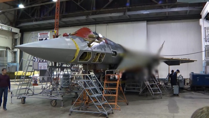
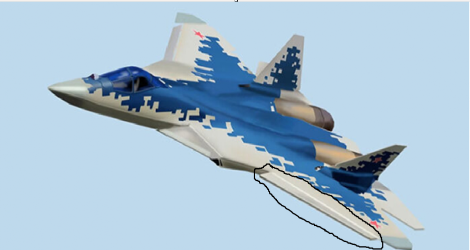
Su-57 Bort number 01 blue. Note the censored area around the LEVCON. Of course they wanted to hide that 1.6 m wide L-band AESA in the leading edge panel.


Su-57 in KnAAZ 2.png
 
Note : many links that I had simply do not exist any more ,sorry and that is the reason I posted only translated versions of them.

If you have the links, you can post them, even if they don't work. For starters, 90% of the time the page will be available by the Wayback Machine e.g.


If you don't have the links, then post the name of article and its author and the periodical's name etc.

Its not hard.

When you post only a translation with no clues as to the source, we don't know where the info is from and can't do our own translation. We also can't redo the translation in the future. Translation software has improved vastly over the lifespan of the forum.
 
From 2010 it was 700W with plans to increase the value to 1 kW in 2011/2012. This is some original Russian NPP 'Pulsar' articles about that. I already posted transl versions.

This one is from 2010 :

МОДЕРНИЗАЦИЯ МОЩНОГО МОДУЛЯ БОРТОВОЙ АФАР L-ДИАПАЗОНА

''Модуль первичной разработки был представлен на конференции «Пульсар-2008», сейчас он осваивается в производстве. Вопрос о его модернизации – ответ на требование оперативного повышения уровня эксплуатационных характеристик, что свойственно быстро развивающимся
областям техники.Главная цель модернизации – повышение уровня выходной импульсной мощности с 400 Вт до 700 Вт в рекордной полосе частот 1 -1,5ГГц в каждом из 4-х каналов модуля. При этом габаритные и присоединительные характеристики модуля остаются неизменными.В основе модернизации – новое поколение интегральных сборок под
названием «усилитель мощности» взамен мощных СВЧ транзисторов, а также развитие принципа объемной интеграции. Модернизированный модуль является приемопередающим устройством с коэффициентом шума в заданной полосе не более 4 дБ. Рассмотрен вариант конструктивной модернизации корпуса с целью повышения технологичности сборки, контроля и ремонтоспособности. По параметру удельная выходная импульсная мощность на единицу
объема модуля полученный результат (2 кВт/л) превышает известные мировые достижения.''
Do we know anything about their cooling requirement and whether the modernization will go on first block of operational Su-57? or is this for second block? is this sort of like APG-85 for F-35 block 4?

You asked about beamwidth and this is also original Russian doc. about that ( already posted and translated).
Be aware that there are data for the transmitting and for the receiving. ∆f1 is in fact radar mode and ∆f2 is IFF mode.
''4.2.1.8 Ширина ДН в азимутальной плоскости по уровню минус 3 дБ при работе в поддиапазоне ∆f1 должна составлять.
4.2.1.8.1 При работе на передачу:
- режим максимальной мощности, град - (130+/-3)/N/cosΘ;
- режим оптимальной ДН, град - (125+/-3)/N/cosΘ
где Θ – угол отклонения главного максимума ДН относительно нормали к антенне, N – число излучателей.
4.2.1.8.2 При работе на прием, град: (135+/-3)/N/cosΘ, где Θ – угол
отклонения главного максимума ДН относительно нормали к антенне, N – число излучателей.
4.2.1.9 Ширина ДН в азимутальной плоскости по уровню минус 3 дБ при работе в поддиапазоне ∆f2 должна составлять.
4.2.1.9.1 При работе на передачу:
- режим максимальной мощности, град - (102+/-2)/N/cosΘ;
- режим оптимальной ДН, град - (108+/-2)/N/cosΘ;
где Θ – угол отклонения главного максимума ДН относительно нормали к антенне, N – число излучателей.
4.2.1.9.2 При работе на прием, град: (120+/-2)/N/cosΘ, где Θ – угол
отклонения главного максимума ДН относительно нормали к антенне, N –число излучателей.
4.2.1.10 Ширина ДН в угломестной плоскости по уровню минус 3 дБ должна составлять 70-90 град. во всех режимах.''
Alright, it actually a lot easier to understand the paragraph when you cited short section like this instead of the whole words salad. Keep it up
Anyway, it seem like instead of giving a direct information about beamwidth, they gave us the theoretical formula to calculate it.
This isn’t the classic beamwidth formula used in antenna theory (which typically involves wavelength and aperture size), but it is a simplified engineering approximation tailored for this specific radar system. Since this is used for AESA system, it is expected that beamwidth increase with boresight angle.
Their formular is: 130/ number of element/ scan angle off boresight.
Each array has 12 T/R modules so we can calculate that:
At 15° scan: the beamwidth is 11.22°
At 35° scan: the beamwidth is 13.22°
At 55° scan: the beamwidth is 18.89°
 
Iirc we don't know much official on megapolis(i.e. su-57m, i.e. blk-4 like refresh).
Lots of guessing and scrapping together most likely speculations.
 
Lots of guessing and scrapping together most likely speculations.

Yeah, papers are good and fine. Tho more often than not the speculations easily goes too way optimistic.

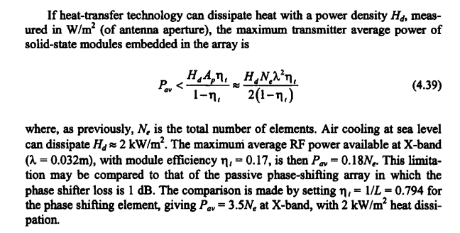
Let's say that L-band array potentials. Especially if one make optimistic prediction on power of the TRM's. Allowances on cooling has to be taken account for. Ausairpower specify cooling was through conduction where the heat flows out of the radar through the metal ribs for dissipation. This limit the cooling capacity to about 1.15 KW/sqm, which in turn limit the average power dissipation of the array. Which can be estimated with following :

1743832854831.png

For AESA TRM of today, typical efficiency of 35% can be assumed. More is possible depend on the class of the amplifiers (How the amplifier are biased that is). The most linear A-class is the least efficient, but also desireable for signal purity. Radar can do however other class e.g B,C which efficiency can reach 60-70%, but filtering is necessary as there would be spurious harmonics from its operations.

Now if A-class is used.. like Zhuk-AE which use A-class and cooling capacity from conduction of 1.15 KW/sqm, 12 elements and L-band say 30 cm wavelength (about 1000 MHz). Using equation above, the available cooling limits the Average power to 334 Watt for 1 array.
Regardless how much Peak power TRM can provide, the average power are limited to that amount. Any increase would require :

-Increase in cooling capacity (say, switch to liquid) with penalty in weight and volume
-Reduction of duty cycle, means low PRF waveform with long pulse which cost the radar in range and minimum range. Long pulse means the radar might not be able to detect close target determined by the pulse length. e.g 1000 microseconds (typical for L-band Radar) equals to minimum range of 1000*150 (1 us of pulse is 150m ), 150000 m or 150 km. You cannot detect target that close. This typically addressed by transmitting a second shorter "cover pulse" waveform, this imply increase in duty cycle.
-More TRM thus increase the surface area one can dissipate heat but do one have the leisure for wing leading edge ?

This isn’t the classic beamwidth formula used in antenna theory (which typically involves wavelength and aperture size), but it is a simplified engineering approximation tailored for this specific radar system.

Not really, you can read in David Adamy's EW-101. That equation is based on an array of dipole antenna, pretty much suitable for a linear array. The basic form of this equation is this :

1743835476901.png

The constant is of course can be adjusted based on test result, but the basic is there.
 
If you have the links, you can post them, even if they don't work. For starters, 90% of the time the page will be available by the Wayback Machine e.g.


If you don't have the links, then post the name of article and its author and the periodical's name etc.

Its not hard.

When you post only a translation with no clues as to the source, we don't know where the info is from and can't do our own translation. We also can't redo the translation in the future. Translation software has improved vastly over the lifespan of the forum.

Thanks for the suggestions .Now I will present some of the available links...

Основные проблемы создания ППУМ для АФАР L-диапазона
СЕМЕНИН С.Н., СОКОЛОВ И.А., ГОЛИКОВ И.В., ВАРЕЦА Н.В
The main problems of creating PPUM for AFAR L-band
SEMENIN S.N., SOKOLOV I.A., GOLIKOV I.V., VAREKA N.V


Опыт разработки и освоения в производстве приемо-передающих модулей АФАР в L-диапазоне
СЕМЕНИН С.Н., СОКОЛОВ И.А., ФУНДА В.Н., СКИЧКО Д.Ю., БАЦ А.В
Experience in the development and development of AFAR transceiver modules in the L-band
SEMENIN S.N., SOKOLOV I.A., FUNDA V.N., SKICHKO D.Yu., BAC A.V

This is interesting, it was 10 years ago .

Международная конференция "Микроэлектроника-2015", г. Алушта, Крым 2015
International Conference "Microelectronics-2015", Alushta, Crimea 2015

Разработка четырехканального приемопередающего модуля L-диапазона на основе GaN-технологии
СОКОЛОВ И.А., СКИЧКО Д.Ю., ФУНДА В.Н
Development of a four-channel L-band transceiver module based on GaN technology
SOKOLOV I.A., SKICHKO D.Yu., FUNDA V.N


БОРТОВАЯ ЛИНЕЙНАЯ АФАР ДЕЦИМЕТРОВОГО ДИАПАЗОНА

А. И. Синани, П.А. Агеев, Г.Ф. Мосейчук, Т.А. Ломовская, И.А. Балина, И.В. Голиков.Все ОАО «Научно-исследовательский институт приборостроения имени В.В.Тихомирова»

 
Last edited:
Do we know anything about their cooling requirement and whether the modernization will go on first block of operational Su-57? or is this for second block? is this sort of like APG-85 for F-35 block 4?


Alright, it actually a lot easier to understand the paragraph when you cited short section like this instead of the whole words salad. Keep it up
Anyway, it seem like instead of giving a direct information about beamwidth, they gave us the theoretical formula to calculate it.
This isn’t the classic beamwidth formula used in antenna theory (which typically involves wavelength and aperture size), but it is a simplified engineering approximation tailored for this specific radar system. Since this is used for AESA system, it is expected that beamwidth increase with boresight angle.
Their formular is: 130/ number of element/ scan angle off boresight.
Each array has 12 T/R modules so we can calculate that:
At 15° scan: the beamwidth is 11.22°
At 35° scan: the beamwidth is 13.22°
At 55° scan: the beamwidth is 18.89°

One correction pls, each array ( antenna) has in fact three TRM's only where each has four channels. So there is 12 working channels or 12 RE ( radiating elements) in total.

AFAR-L Su-57 MAKS 2007 1 mod.JPG

12 RE in the upper row.

AFAR L mod.JPG

12 RE in the bottom row.

AFAR-L Su-57 MAKS 2009 1 mod.JPG
 
You would still use the number of element to calculate beamwidth so result is same.

What do you mean?
He's saying its a 12 X 2 element array.

so therefore 130/2 = 65 deg beam width in vertical scan at 0 degrees and 85 degree beamwidth at +40 degrees?

You can't really tell more than "maybe, up / down" at best.
 
Long pulse means the radar might not be able to detect close target determined by the pulse length. e.g 1000 microseconds (typical for L-band Radar) equals to minimum range of 1000*150 (1 us of pulse is 150m ), 150000 m or 150 km. You cannot detect target that close. This typically addressed by transmitting a second shorter "cover pulse" waveform, this imply increase in duty cycle.
Really not my area of expertise, but a couple of things jump out here where a little explanation might help the rest of us.

"1 us of pulse is 150m" Actually it's C/1,000,000, so, 300m covered within the length of a 1us pulse (299.702m if we're being precise for the speed of light in air), but there and back, so halved. (Did this one way back in about '84 covering length of a bit in an ethernet wire, Grace Hopper had a good demo of it that's on Youtube somewhere).

I suspect you might be able to work around it using advanced waveforms, which would link what element of the waveform you're getting bounced back with a specific timeslice and range. So if you imagine your waveform modulated as (simplistically) ABCDE...XYZ, and you're currently seeing DEF returned, then you know when you transmitted it and therefore what range it corresponds to, and you'd be expecting GHI next at a closely corresponding range.
 
He's saying its a 12 X 2 element array.
I don’t think there is more than 1 line of element in the elevation. Because T/R modules need some spacing between them to steer the beam eletronically.
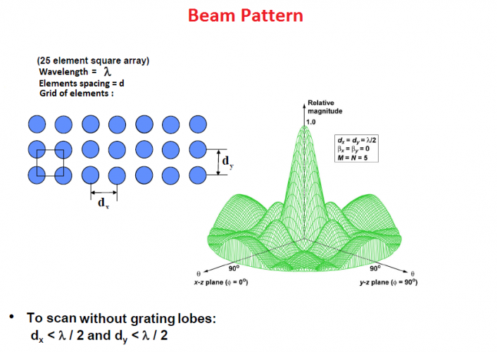
Typically, this spacing would be roughly half wavelength. With L band (1 Ghz, wavelength 30 cm) then the spacing would be something like 15 cm, I don’t think the leading edge is that thick.
IMG_8386.png
 
Sure, some people are claiming the L band AESA is some Uber-stealth-detector technology with a bajillion watts of output, which it really isn't.
No ubers involved(arguably whole point of L band is you don't need to radiate madly), you can see indeed where it meets its limitations right now, in ongoing conflict. But with high degree of certainty it is indeed a wide swath scanning solution, superior to x band for the L/O aircraft warning purposes.

Evidence on subject is controversial, but evidence for is direct, evidence against is "absence of evidence".

Within chosen format it is by necessity a warning compromise, but it is already quite a lot.
 
Last edited:
The wingspan of the entire aircraft is 14.1 meters, and height of aircraft is 4.6 meters according to a simple google search. Roughly what is estimated length of the entire N036L antenna and with that estimated length and size what is needed at minimum for 1-2ghz tracking to work or what frequency would work with that sized antenna (like C-band or S-band)?

1743866335160.png
1743866489657.png
There is the cockpit, the LEVCONs, supposedly the placement of the L-band radar and the wing tips which look like 6 pieces of the aircrafts that measure the entire length of the wingspan of the aircraft which is supposedly 14.1 meters. If anything the supposed L-band placements seem as big as one half of the cockpit, LEVCON and wing tips combined which we can divide 14.1 meters by 4 and get 3.525 in meters length and I suppose that is where the L-band radar would be placed.
 
Last edited:
That's okay for a threat warning system, but not great for locating a target.

Especially when the radar is 2D not 3D ,so there must be some kind of support ,data-sharing.

You would still use the number of element to calculate beamwidth so result is same.

What do you mean?

Of course ,12 of them but with that kind of positioning ,suppose that can be used when LEVCON's and wingslats are in neutral position or deflected downwards.


САМОЛЕТНАЯ АНТЕННАЯ РЕШЕТКА​


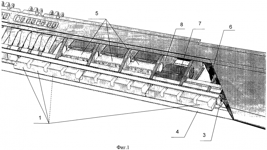
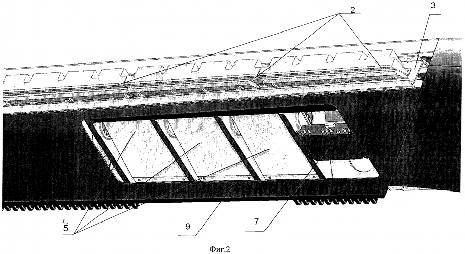
''Для этого излучатели вертикальной поляризации установлены в плоскости, перпендикулярной поперечной оси передней кромки крыла, а активные СВЧ устройства и схема суммирования закреплены в отсеках либо подвижного, либо неподвижного носка крыла между силовыми поперечными диафрагмами.''

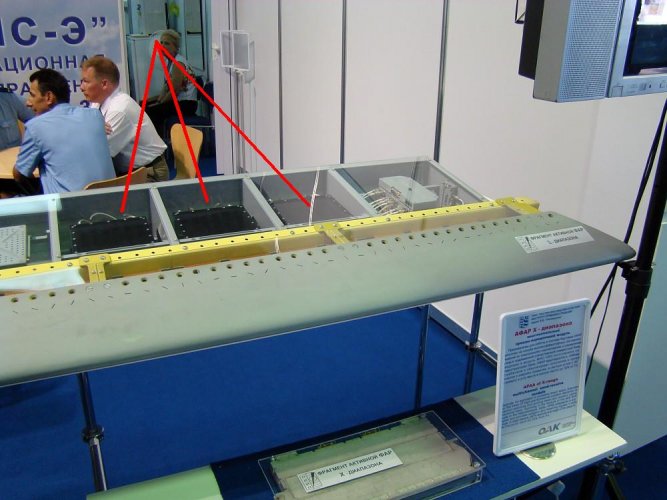
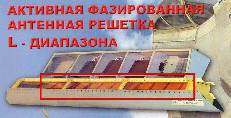
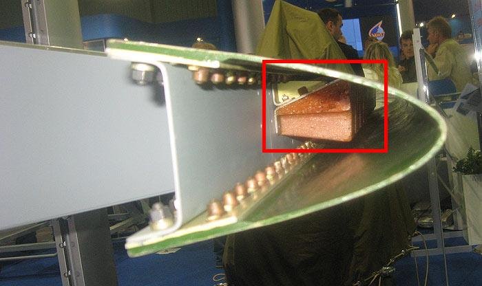
We can see three blocks with four RE's on each of them.


L band AESA.png

L band AESA 1.png

One block with 4 RE's.

NIIP-AESA-L-Band-Brochure-3S.jpg


''Самолетная антенная решетка состоит из излучающей системы 1, выполненной из отдельных излучателей 2, установленных на панелях 3. Излучающая система 1 крепится на передней стенке 4 носка крыла и закрывается съемным радиопрозрачным обтекателем 5, являющимся составной частью носка крыла.
Активные СВЧ устройства (например, приемопередающие модули) 6, суммирующее устройство 7, устройства распределения и фазирования 8 располагаются за передней стенкой 4 носка крыла, в отсеках между силовыми поперечными диафрагмами 9 носка крыла. Демонтаж и монтаж аппаратуры подвижной части носка крыла обеспечивается съемом радиопрозрачного обтекателя 4, а также доступом через нижние люки 10 носка крыла.''

Аbout cooling requirement there is very little info about that ....

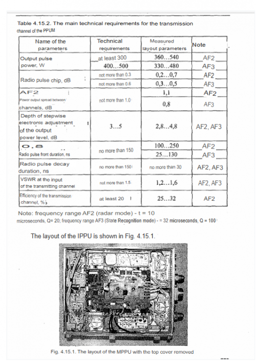
''Самые теплонагруженные усилительные паллеты ЮР 1268 (поддиапазон частот AF2) располагаются непосредственно над отверстиями канала жидкостного охлаждения.''

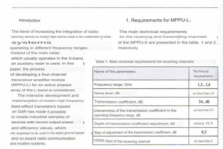
Основные проблемы создания ППУМ для АФАРL-диапазона


''AF2 (радиолокационный режим)'' ,so this is radar mode.


@Null

There was a plan to integrate only two arrays in wingslats with width of 10λ ( 240cm) but they decided to integrate four instead of two antennas ( 1.6 m wide).
 
1743878465450.png
1743878916485.png
Alright so the wings do operate in radar mode, which is why Kopp made the estimated radar performance graphs, this old info is new info to me. I will cross my fingers if he get additional information on the Su-57M avionics.
Edit: going through squirrels PDF pages
1743879905017.png
Literally more pdf pages from squirrel stating the L-band operates as a radar. I think we reached a verdict here. I wonder if @stealthflanker can give estimated radar target tracking performance based on the antenna size, modules used and power output with the GaN modules used for the L-band radar.
 
Last edited:
@ Null

From 2008 :

''Сегодня ФГУП "НПП "Пульсар" создает изделия, отвечающие самым высоким требованиям. К ним относятся:
• не имеющий аналогов, сверхширокополосный четырехканальный приемо-передающий модуль L-диапазона (1–1,5 ГГц) с выходной мощностью 200 Вт на канал для РЛС с активной фазированной антенной решеткой (АФАР), объединяющий функции госопознавания, международного опознавания и обзорной РЛС и размещаемый в крыле са-
молета (рис.1). Модуль отличается рекордно малыми габаритами и характеризуется высоким отношением выходной СВЧ-мощности к объему (2 кВт/л) . Он позволит поднять энерговооруженность перспективных РЛС с АФАР, предназначенных для самолетов пятого поколения; ''


These are unavailable links now...


Interview with Yuri Bely from 2015

 
I am surprised there is no speculation or information about its RWR. I have seen photos showing that the wingtips have their own L-band arrays for RWR purposes, but not sure how much stock to put in that. There is the Himalayas ECM suite in the tail and the 3 radars, but I would be very surprised and find it very unusuall if these are also being used for RWR.
 
I am surprised there is no speculation or information about its RWR. I have seen photos showing that the wingtips have their own L-band arrays for RWR purposes, but not sure how much stock to put in that. There is the Himalayas ECM suite in the tail and the 3 radars, but I would be very surprised and find it very unusuall if these are also being used for RWR.

It's already discussed, there is 8 AESA ( four in X band and four in L band) plus 4 EW/ECM antennas of the L402 Himalay inside of the wingtips.Besides this, L402 uses all eight AESA.
 
Back
Top Bottom