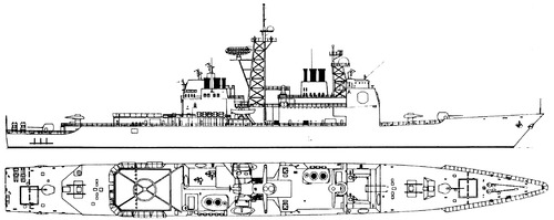
Spruance-Based AEGIS Destroyer (DD 999)

TomS

ACCESS: Above Top Secret
Senior Member
Joined
16 April 2008
Messages
8,636
Reaction score
11,071
Found another interesting document in my files this past weekend – a fairly early (March/April 1975) presentation on the Litton feasibility study for a Spruance-derived AEGIS destroyer that eventually became the DDG 47, then CG 47 Ticonderoga class. At this point, this design was being referred to as the DD 999/AEGIS configuration, a designation that I have never seen anywhere else.

DD999-01.jpg

If you are wondering why they were using DD 999, at this time the Imperial Iranian Navy (IIN) was planning to build six ships, which the USN designated DD 993 through 998 for record-keeping purposes. The four that were ultimately ordered later became the DDG 993 Kidd class in USN service. (DD 997 was eventually recycled for the proposed DDH that became Hayler and DD 998 may have also been recycled for the second DDH that Congress authorized but never funded.)

The Iranian DD 993s essentially followed the plan for an AAW Conversion of the baseline DX Spruance class, with some Iranian climatic changes added. In the edits, the term “DD 963 Conversion” has largely been replaced with “IIN DD 993”, and there are some notes that work on the IIN design could cover some of the costs of the DD 999/AEGIS version as well, because there were some commonalities.

Note: these slides are a marked-up draft, showing changes requested before the slides were finalized for presentation. And quality is not great – these are photocopies of transparencies that someone then marked up and photocopied again. And then I photographed them using a hand-held phone camera. Best I can do at the moment. I'm not worried about the Litton marking because it's nearly 50 years old at this point and of only academic interest.
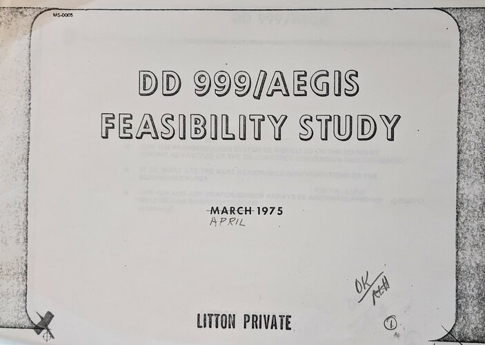
 
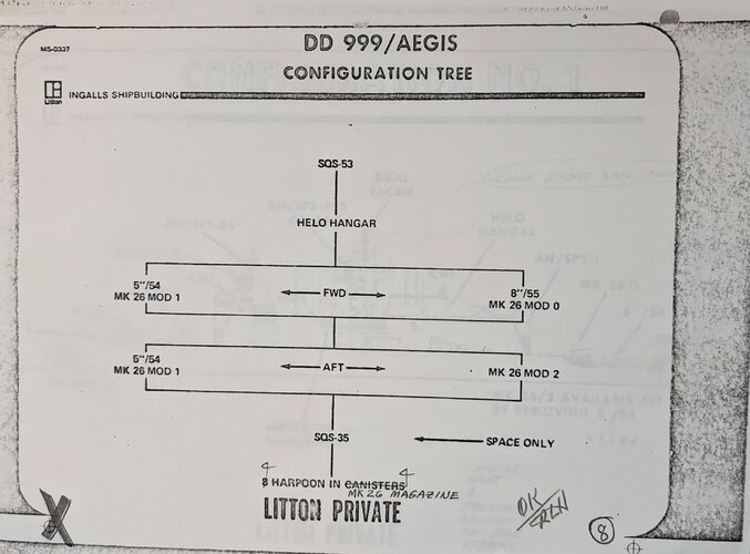
Up first, there is a “configuration tree” showing the tradeoffs between various proposed gun and missile launcher systems.

DD999-08.jpg
  • Fitting the 8”/55 gun forward in place of the 5”/54 would require a reduction of the Mk 26 from the Mod 1 (44 round) version to the Mod 0 (24-round) version.
  • Removing the aft 5”/54 allowed the aft Mk 26 to grow from Mod 1 to Mod 2 (64 missiles)
  • There was a space reservation for the SQS-35 Independent Variable Depth Sonar)
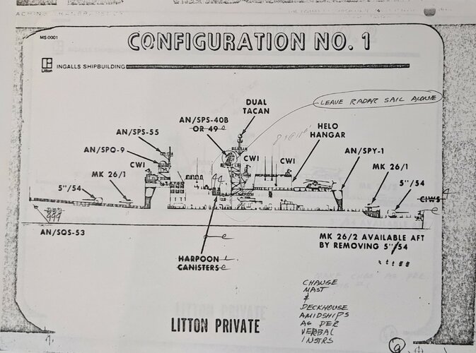
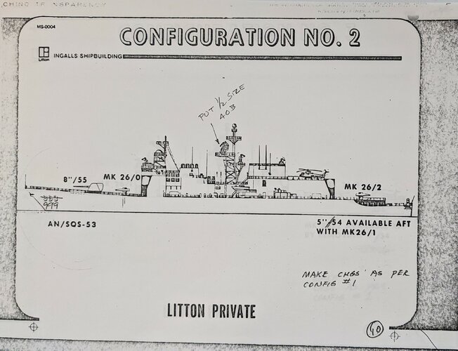
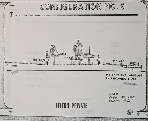
Based on these trades, three different DD 999 AEGIS configurations are shown. The most interesting thing is that these designs use deckhouses with the array faces angled at 45-degrees off centerline and arranged symmetrically around the long axis of the ship. This is more like the configuration seen in the CGN-42 and other early AEGIS proposals, not the asymmetric version finally fielded on the Ticos. The array faces are also set about a half-deck lower in the structure, and the aft antennas are pushed much further back in the ship, to the extent that two of the three proposed configurations actually have the helo pad and hangar on top of the aft radar deckhouse.

DD999-09.jpg

DD999-10.jpg

DD999-11.jpg


All three configurations delete the RAST helicopter hauldown and handling equipment, and Configuration 3 may not even have a hangar (or it may use an elevator like the Virginia class, which was terrible).

In all three, the separate Harpoon canisters are deleted in favor of carrying Harpoon in the Mk 26. This was planned early in the Mk 26 lifecycle, but apparently never implemented.

The SQS-53 bow sonar was standard. There was also a space reservation for the SQS-35 Independent Variable Depth Sonar, which was eventually replaced across the fleet by SQR-18 or -19 towed arrays.

The drawing and some later tables show SPS-40B as the preferred 2d air search radar, as in the DD 963. The actual Ticos got the larger SPS-49 instead.
  • Configuration 1 Is essentially the “baseline” configuration with 2 Mk 26 Mod 1 launchers (88 missiles total) and two Mk 45 5”/54 guns. This version also deletes the Phalanx on the fantail; some data tables later in the slide deck suggest it would still be included elsewhere
  • Configuration 2 adds the 8-inch gun forward, reduces the forward Mk 26 to Mod 0 (22 rounds), deletes the 5-inch gun aft, and increases the aft Mk 26 to Mod 2 (64 rounds), preserving the same total magazine capacity.
  • Configuration 3 is basically like Configuration 1 except it moves the aft SPY arrays forward, eliminates the helo hangar on the roof, and relocates the helo pad to the fantail. This version also shows a Phalanx on the deckhouse roof, abeam of the aft stack (I’d guess there is another one forward, hidden by the forward stack)
In Configurations 1 and 3, the aft 5-inch gun could be deleted, adding 20 missiles to the aft launcher for a total of 108 rounds. In Configuration 3, a 5-inch gun could be added aft, deleting 20 rounds from the aft launcher for a total of only 68 rounds.
 
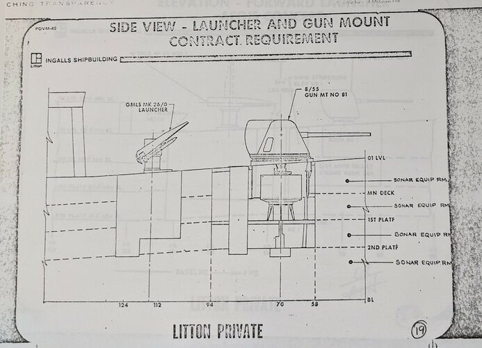
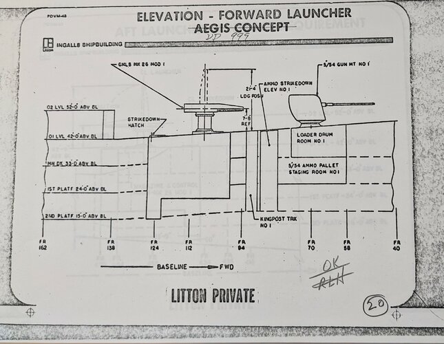
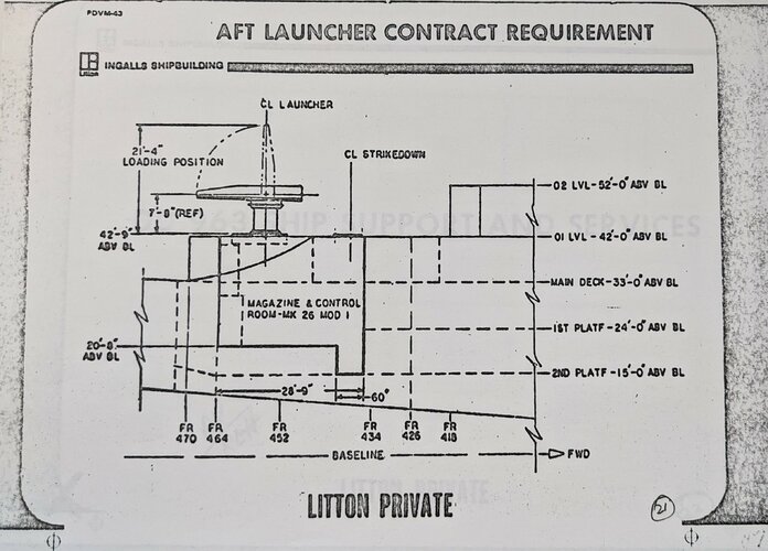
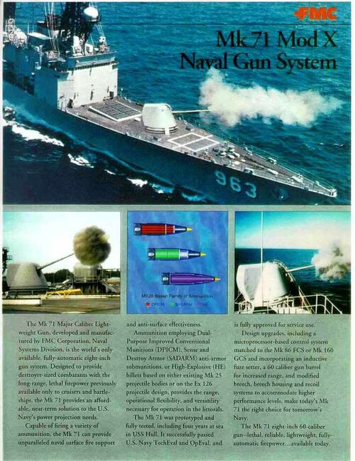
There are also some “side view” drawings that illustrate the gun and launcher installations. These show why the 8”/55 was so hard to retrofit – it pushed a full deck deeper into the hull than the 5”/54. They also show the extent of the Mk 26, and why VLS was such a significant rework of the hull. I think the aft one is from the DX Conversion contract design, because it shows a step up to the helicopter pad on the 02 deck and a step down to the main deck aft of the launcher, which none of the DD999/AEGIS designs had at this stage.

DD999-19.jpg


DD999-20.jpg


DD999-21.jpg
 
Wow! Nice find! I really like the 8" armed version. I presume it would be the single barelled version.
I see that the final Ticonderoga superstructure did not changed much from these earlier designs.
 
Incredible find! Would these count as Tico preliminary designs, even if they weren’t ordered by NAVSEA? I’m sure the lessons learned in a “private design” like this would applied to the real thing. Out of curiosity, how old are the files, on your hard drive I mean.
 
OK, those designs with the helo deck at the O3? O4? level feel like some serious absinthe was involved somewhere. I don't think anyone asked the pilots what they thought about that solution....

And yeah, I agree that this was most likely based on the "standard aegis layout" that was used in the test facility and which the Strike Cruiser and Aegis Virginia proposals were designed around.
 
Wow! Nice find! I really like the 8" armed version. I presume it would be the single barelled version.
I see that the final Ticonderoga superstructure did not changed much from these earlier designs.

I'd say quite a bit changed. Compare to this (sorry, it's the other side, but you get the idea):

1688413564530.png

In the final build:

1) The array faces are rotated (one forward, one port, one aft, one starboard) instead of being angled on the P/S bow and P/S quarter.
2) The arrays are elevated, especially the aft ones, which are now above the helicopter hangar, not below it
3) The helo hangar and pad are restored to the Spruance configuration on the 02 deck.
4) The main mast is completely redesigned, with SPS-49 behind the lattice mast
5) The illuminators are all on the deckhouses, none on the masts
6) Harpoon is reinstated, aft on the fantail
7) Phalanx is relocated amidships
8) The stacks are more like the original Spruance design. (There is a detail I haven't posted yet about a new, angled, stack exhaust design from the DD 999)
9) There's another enclosed space added at the base of the mainmast

And worth mentioning, though I didn't post it, this Configuration 1 was around 8,600 tons, compared to the 9,600 tons of the final Ticonderoga design.
 
Wow! Nice find! I really like the 8" armed version. I presume it would be the single barelled version.
I see that the final Ticonderoga superstructure did not changed much from these earlier designs.
Yes, the 8"/55 Mk71 was a single barrel turret, 20 tons heavier than the 5" Mk42 turret. USS Hull tested the entire concept for a while.
 
Are the 45⁰ arrangement of the SPY-1s the result of the use of a pair of Mark 20 Mod 0 deckhouses, or had they decided by that point that the Spruance hull lacked the margins?
 
Last edited:
Incredible find! Would these count as Tico preliminary designs, even if they weren’t ordered by NAVSEA? I’m sure the lessons learned in a “private design” like this would applied to the real thing. Out of curiosity, how old are the files, on your hard drive I mean.

The Spruance and Tico family were always Litton designs -- NAVSEC was cut out of the design process almost entirely. This is Litton's initial (or at least early) feasibility study. Basically, them saying "Yeah, we can totally fit AEGIS on a Spruance hull" to the Navy. PD would follow after this.

It's new on my hard drive today -- I've had the paper file kicking around in a box for almost 20 years, probably.

OK, those designs with the helo deck at the O3? O4? level feel like some serious absinthe was involved somewhere. I don't think anyone asked the pilots what they thought about that solution....

And yeah, I agree that this was most likely based on the "standard aegis layout" that was used in the test facility and which the Strike Cruiser and Aegis Virginia proposals were designed around.

Especially when they deleted RAST. It's a giant one-finger salute to aviation.

Are the 45⁰ arrangement of the SPY-1s the result of the use of Mark 20 Mod 0 deckhouse, or had they decided by that point that the Spruance hull lacked the margins?

I think this was a bit cut down from the original deckhouse, in that it's lower and more integrated into the hull structure. But probably same geometry from transmitter to array face, because that's the hardest part. (And then they went and reworked that in the final design.)
 

The Spruance and Tico family were always Litton designs -- NAVSEC was cut out of the design process almost entirely. This is Litton's initial (or at least early) feasibility study. Basically, them saying "Yeah, we can totally fit AEGIS on a Spruance hull" to the Navy. PD would follow after this.

A massive thank you for posting these, absolutely fascinating.

I wonder if this work may have originated earlier than the presentation they are included in was made. The Navy told the House Appropriations Committee in early May 1974 that they had studied a DDG-963 Aegis configuration as an alternative to the DG Aegis concept (see attached) image. The conclusion, a cheaper lead ship but higher follow ship costs for a higher overall programme cost, seems reasonable. The superior ASW performance being a product of carrying over the DDG-963 sonar fit.

I have a hypothesis, for which I have no direct evidence, that when conceiving the DG Aegis ship design the Navy did so on the assumption that the DDG-963 class would be back-fitted with Mk-26s, a pair of illuminators (AN/SPG-62) and the 8"/55. Had that of happened the two ships would have gone together like a hand in a glove, the DDG-963s having everything the DG Aegis concept didn't (guns, SQS-53, two LAMPS versus one) and the DDG-963s could have received Aegis radar data via datalink from the DG Aegis ships (one of the original key features of Aegis; early trials transmitted data from the shore-based test facility, via Fleet Combat Direction Systems Support Activity (FCDSSA), in Dam Neck, Virginia, to USS Farragut using Link 11). The result would have been a DG Aegis and back-fitted DDG-963 combination having four illuminators, three Mk-26s, a pair of guns, three LAMPS and a capable sonar fit.
 

Attachments

  • May 1974 DG Aegis Alternatives.png
    May 1974 DG Aegis Alternatives.png
    274.6 KB · Views: 60
Last edited:
I wonder if this work may have originated earlier than the presentation they are included in was made.

It's certainly possible. 1974 might have been a very rough order of magnitude estimate, with these studies (probably early 1975) were exploring the design space a bit.

Cooperative Engagement was one of those things that was promised from the early days of AEGIS but took forever to actually come into service. Conceived in the 1970s, didn't even become a Navy acquisition program until 1992, not seriously fielded until the late 1990s or even 2000s.

 
Last edited:
Remember that the 963 was designed as part of the DG/DX study, which required a design which could be back-fit (or built) as an AAW ship (presumably with Standard Missiles -- that was the Iranian ship, in effect). The idea was that the air threat might grow to the point where carriers needed more AAW escorts, but the same number of ASW ships. In effect Spruance was an AAW ship with the AAW part removed on paper. That's why the Iranian ships were possible. It's also why Spruance had so much empty space as built. I don't think provision for the 8in gun was included.
 
A fascinating post indeed. It's always exciting when someone unearths a long-forgotten study.

I am intrigued that they attempted to retain as much ASW capability as possible (LAMPS, SQS-35) on what could be considered to be an AAW platform given the demands SPY and AEGIS made on the overall layout of the ship. Configuration 3 is perhaps more realistic in just providing a landing spot aft.

I am in two minds about the usefulness of the 8in Mk.71, the trade-off in missile magazine capacity doesn't necessarily feel worth it. It feels like it belonged more on the standard DD-963 as a refit.

Certainly the Tico looks like a much better packaged design overall, but these early concepts are very interesting in showing how the concept evolved.
 
Remember that the 963 was designed as part of the DG/DX study, which required a design which could be back-fit (or built) as an AAW ship (presumably with Standard Missiles -- that was the Iranian ship, in effect). The idea was that the air threat might grow to the point where carriers needed more AAW escorts, but the same number of ASW ships. In effect Spruance was an AAW ship with the AAW part removed on paper. That's why the Iranian ships were possible. It's also why Spruance had so much empty space as built. I don't think provision for the 8in gun was included.

The 8-inch gun was a possibility in the DX conversion plan. It's one reason why the forward Mk 26 would have been limited to 24 rounds. They were able to fit the larger VLS later in part because the 8-inch gun was no longer an issue.
 
I wonder if this work may have originated earlier than the presentation they are included in was made.

It's certainly possible. 1974 might have been a very rough order of magnitude estimate, with these studies (probably early 1975) were exploring the design space a bit.
Circling back on this, Electronic Greyhounds says NAVSEC and AEGIS project office personnel met after the DD963 contract award to talk about incorporating AEGIS on the 963 hull. This would be c. 1970-71. At this time, they knew the Mark 20 deckhouse would not fit, but that the individual systems would. This was while detailed design was underway for DD963. Admiral Sonenshein, then director of naval Ship Systems, ordered that any design changes on DD963 to things like stability, power generation, etc. should not prevent future AEGIS installation. At the same time, the AEGIS project office started looking at how to repackage AEGIS into the DD963 hull, ostensibly using the Spruance as a proxy for any future simplified AEGIS installation. (This info appears to be taken from an interview with Sonenshein and RD Inman's 1988 article "From Typhon to AEGIS" in Naval Engineers Journal, which I used to have but can't find at the moment.)

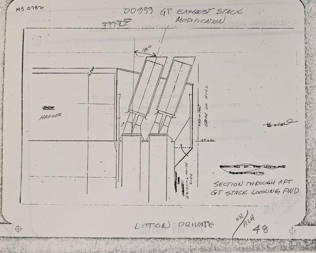
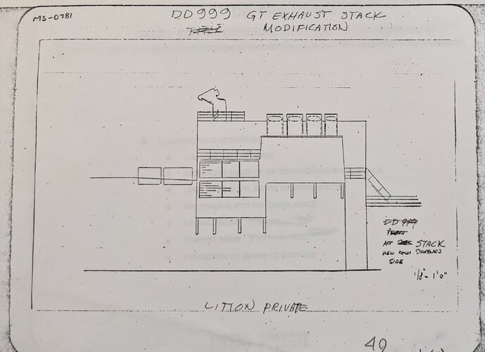
These feasibility studies were apparently somewhere early in that process, because Electronic Greyhounds says that by the end of this study, the array faces shifted 45 degrees to fit around the exhaust stacks. In the configurations posted above, they looked at repackaging the exhausts instead. The new design is similar to one seen in the flight-deck Spruance concepts from the same era, flattened and with the tips angled out toward the deck edge.

DD999-48.jpg DD999-49.jpg
 
Quite a bit of the relevant history is here. It seems the AEGIS simplification effort began in 1970, using the Spruance as the intended recipient vessel..

In early 1970 Captain Louis Stecker, who had named Aegis, was now a staff officer in the Office of the Secretary of Defense. He had been following the Aegis project, and realized that with the present weight and volume of the Aegis system, it might never get a target ship. The system needed reduction and simplification, and he managed to push through a modification to the RCA Aegis contract calling for a simplification study. [King, Radm. Randolph W., USN, and Palmer, Lcdr. Prescott, USN, eds, Naval Engineering and American Seapower, Nautical and Aviation Publishing Company of America, Baltimore, MD, ISBN 0-933852-73-8, pp. 356-357] [Inman letter]

Captain Bryce Inman retired from the Navy in 1970 and went to work for RCA in the Aegis program office, where his first job was to take charge of the Aegis simplification study. Inman could not believe how much the system had grown in features, weight, and volume since he had worked on the Withington Committee. He could see many areas in the system that could be deleted or simplified, but first he needed to find out how much the system needed to be shrunk to fit into a feasible target shipbuilding project. He picked the new Spruance destroyer class as his target because if Aegis could not be shoehorned into the Spruance class it probably would not see enough new receiving ships to make Aegis project continuation worth while, in his estimation.

Inman got the Spruance booklet of general plans to use as a target to determine how much weight and volume would have to be removed from the Aegis components. His resultant study showed ways to cut the SPY-1 radar transmitter and signal processor weight in half and to cut the fire control equipment weight by one third. Furthermore, his team identified a number of nice-to-have features and equipment that did not seem vital to the Aegis mission. If all recommendations were taken, Aegis could be installed in Spruance class destroyers. The Aegis project office sent the study report to the Naval Ship Engineering Center at Hyattsville, MD, where engineers confirmed the results, but also found that Aegis, in that form, would use up all the Spruance lifetime weight and overturning moment allowance. The culprit was the modular deck house concept that so many senior reviewers thought was such a neat idea and still insisted upon it. [Inman letter]

.....

Admiral James L. Holloway III became Chief of Naval Operations on 1 July 1974, and one of his first actions was to cancel the single purpose Aegis AAW escort project. Instead, he said he wanted a conventional multi-purpose destroyer equipped with Aegis. Things were falling into place for Aegis. The first of the new Spruance (DD 963) destroyer class had been laid down on the building ways in November 1972 and its full load displacement was 7,800 tons. Aegis was now able to be fitted into a small 5,000 ton warship, and the DD 963 hull was a natural candidate. The Chief of Naval Operations approved of the idea, and and his Fiscal Year 1978 shipbuilding program budget to Congress included an Aegis ship (DDG 47) to be built on a Spruance Class hull. [Inman Letter]
 
I wonder if this work may have originated earlier than the presentation they are included in was made.

It's certainly possible. 1974 might have been a very rough order of magnitude estimate, with these studies (probably early 1975) were exploring the design space a bit.
Circling back on this, Electronic Greyhounds says NAVSEC and AEGIS project office personnel met after the DD963 contract award to talk about incorporating AEGIS on the 963 hull. This would be c. 1970-71. At this time, they knew the Mark 20 deckhouse would not fit, but that the individual systems would. This was while detailed design was underway for DD963. Admiral Sonenshein, then director of naval Ship Systems, ordered that any design changes on DD963 to things like stability, power generation, etc. should not prevent future AEGIS installation. At the same time, the AEGIS project office started looking at how to repackage AEGIS into the DD963 hull, ostensibly using the Spruance as a proxy for any future simplified AEGIS installation. (This info appears to be taken from an interview with Sonenshein and RD Inman's 1988 article "From Typhon to AEGIS" in Naval Engineers Journal, which I used to have but can't find at the moment.)

These feasibility studies were apparently somewhere early in that process, because Electronic Greyhounds says that by the end of this study, the array faces shifted 45 degrees to fit around the exhaust stacks. In the configurations posted above, they looked at repackaging the exhausts instead. The new design is similar to one seen in the flight-deck Spruance concepts from the same era, flattened and with the tips angled out toward the deck edge.

View attachment 702960View attachment 702961
The problem was exacerbated by the forward deckhouse which had to be over the bridge and higher than it needed to be while adding structural problems to the bridge. In the case of the DD-963 hull, which was used early in the engineering development program to focus simplification studies, the off-center uptakes caused more difficulties, particularly for the after deckhouse.

The disadvantages of the deckhouse concept were demonstrated when NavSec made an Aegis DD-963 design conversion feasibility study using the Deckhouse Mark 20 concept. The deckhouse concept was finally abandoned for the CG-47 design, and many of the originally claimed advantages were recovered at the production test site where systems could be assembled and groomed prior to ship installation.
 

Attachments

  • FROM TYPHON TO AEGIS.pdf
    1.4 MB · Views: 45
Thanks for the article! Apparently Inman replied to a couple of comments on the article in the July 1988 issue. I don't suppose you have that one too?
 
Last edited:
So, we have a bit more info on the timing of the whole DDG-47 preliminary design. That was completed by April 1976, which suggests two possibilities to me -- that these DD 999/AEGIS feasibility studies were entirely a Litton in-house exercise, without a whole lot of insight into what NAVSEV and the AEGIS Project Office were up to, or that there was a major rework between early 1975 and April 1976. I am leaning toward the former -- Litton keeps using DDD 999, when I think DDG 47 was the AEGIS PO's preferred language from 1975, if not earlier.

From:
PERFORMANCE OPTIMIZATION IN SURFACE WARSHIP DESIGN by JAMES RUSSELL FITZSIMONDS (MIT Masters Thesis, May 1980)

While this was going on [Note: "this" being the debate about DG/AEGIS vs DLGN vs CSGN], work had been done to adapt Aegis to the basic DD-963 hull and power plant. By April of 1976 the preliminary design of the
DDG-47 was completed. The Secretary of Defense approved the DDG-47 program in December of 1976 and Congress authorized it in 1977. Plans also proceeded for a nuclear-powered cruiser class of Aegis ships - the CGN-42. By the end of 1979 this program had been shelved due to excessive cost.
 
So, we have a bit more info on the timing of the whole DDG-47 preliminary design. That was completed by April 1976, which suggests two possibilities to me -- that these DD 999/AEGIS feasibility studies were entirely a Litton in-house exercise, without a whole lot of insight into what NAVSEV and the AEGIS Project Office were up to, or that there was a major rework between early 1975 and April 1976. I am leaning toward the former -- Litton keeps using DDD 999, when I think DDG 47 was the AEGIS PO's preferred language from 1975, if not earlier.
I disagree. I think this started as a Litton in-house proposal to the Navy, and there was a major rework.

I know the USN will throw a major rework in, just because some admiral got a wild hair, see how long they were trying to keep the Mk20 deckhouse.
 
I did a few sketches last night and these were remarkably close to just having the Mk 20 deckhouse, if they did not incorporate the deckhouse itself they kept most of it's internal arrangements. The distance between forward and aft superstructure bulkheads and air intakes and the like that were in the way are near exact the length of the Mk 20 deckhouse as far as my research gave me.

That said, I am surprised by the separation of the SPY-1 arrays, the Tico already has the largest separation of the SPY-1 of any design as far as I have checked (even CSGN Mk 2 has them closer) and these are even further apart, although their 45 degree angle negates that a bit.

I do wonder if this is something Litton did in-house without knowing about the issues with array separation for handing off targets between the arrays, or if this is actually more serious but the issues with the array separation are less serious then I have considered them so far in my design ponderings. (the array separation vs the engine room separation was a major driver for the layout of my conventional powered strike cruiser AU design, for example)
 
I think that's likely. The narrative I see a couple of places is that the AEGIS DD963 adaptation started with basically the Mk 20, just reworked to eliminate the separate hull and deckhouse structural members to save weight. That also allowed them to move the bridge up above the array faces.
 
Is it true that there was an anti-aircraft warfare (AAW) modernization proposal to replace the Spruance class DDs' Mark 4 AWHS (8 + 16 ASROC) with the Mark 26 Mod 0 GMLS (24 missiles) at the fore?

Is it also true that the 29-cell or 32-cell tactical-length Mark 41 VLS could fit in the same space as the Mark 26 Mod 0?

Sources?

Yes, the Spruances were specifically designed for that upgrade path.

They were also designed to take an 8-inch Mk 71 mount forward in place of the 5-inch Mk 45. When the Mk 71 was abandoned, that left more room forward, which is how they ended up with a 61-cell strike-length Mk 41 forward in place of the ASROC launcher.
When the U.S. Navy acquired the Kidd class DDGs after the 1979 Iranian Revolution, was the Mark 71 MCLWG also planned for the Kidds? Did the Spruances and Kidds have the same internal arrangement at the fore?
 
The Kidd's do have the same internal arrangement for (except for having the Mk 26 from construction instead of the Mk 4 AWHS) however the weight margins on the Kidd's were filled up quite a bit more. The Kidd's were heavier and had an higher centre of gravity.

While the original design of the Spruance allowed for the upgrade to the Mk 71 and the Mk 26s both on one ship, the Kidd's with their fittings and tropical ventilation systems are likely already using the margins reserved for the Mk 71 gun.

It has been 10 years since I wrote it down so I suspect some things could be described better by now, but an general outlook of everything that was possible on the Spruance hull is described in my Project DX post on shipbucket http://www.shipbucket.com/forums/viewtopic.php?t=4465
Assuming that the Kidds kept their fore 5-inch Mark 45 instead of switching over to the 8-inch Mark 71, would the Kidds have enough space for the 61- or 64-cell strike-length Mark 41 VLS at the fore just like the Spruances?

I also understand that it would have been impossible to fit the 61- or 64-cell strike-length Mark 41 VLS at the aft of the Spruances and Kidds due to the very limited available space above one of the generators. You have explained on Shipbucket that both the Spruances and Kidds had space for the 44-missile Mark 26 Mod 1 GMLS at the aft. Did the Spruances and Kidds have space for the 61- or 64-cell tactical-length Mark 41 VLS at the aft?
 
Maybe this can help with the size issue. I've drawn all 3 (Spruance, Kidd and Ticonderoga) for a boardgame company and not yet created the side views for them.

Spruance:
1719812004394.png
Kidd:
1719812020565.png
Ticonderoga:
1719812078768.png
 
Tzoli, may I know your references for the Kidd superstructure being longer on a shorter hull then the basic Spruance? Also the gun being further forwards? Before we make any assumptions based on size of things based on them, let's make sure they are accurate.
 
Assuming that the Kidds kept their fore 5-inch Mark 45 instead of switching over to the 8-inch Mark 71, would the Kidds have enough space for the 61- or 64-cell strike-length Mark 41 VLS at the fore just like the Spruances?

I also understand that it would have been impossible to fit the 61- or 64-cell strike-length Mark 41 VLS at the aft of the Spruances and Kidds due to the very limited available space above one of the generators. You have explained on Shipbucket that both the Spruances and Kidds had space for the 44-missile Mark 26 Mod 1 GMLS at the aft. Did the Spruances and Kidds have space for the 61- or 64-cell tactical-length Mark 41 VLS at the aft?
It is unlikely that the Kidds would NOT have the space for the Mk 41, although it is possible that the Kidd's have different use for the forward spaces under the assumption that they would never get the Mk 71.

Aft, fitting anything up to Mk 26 in size should be possible. I think the tactical length was about that size, would have to check.

In the end it all comes down to weight margins though. It could be that fitting an 61 cell Mk 41 forward would run into the same issue that fitting an Mk 71 might run into: the Kidd were already heavier and topheavier then the Spruances so there might not have been enough margins in the design for that upgrade.

All that said, I suspect one of the main reasons the Kidd's never got the Mk 41 was the fact that you actually gain not that much. Yes Mk 41 is an newer, more reliable system, so there are good reasons why it was fielded on all following ships, but if the Mk 26 was already on board, most of what you gain is the ability to fire Tomahawk (while at that point you lost the ability to fire ASROC)
Was the reason the U.S. Navy installed the strike-length Mk 41 VLS onto the Spruance class DDs is to increase the number of Tomahawk VLS warships including the Ticonderoga class DDGs / CGs in the late 1980s until the new Arleigh Burke class DDGs entered service?
 
Probably it was to get more tomahawks to sea, and possibly also the fact that ASROC got old and was to be replaced with VL-ASROC. This can be proven by the fact that only one Spruance did not get either the Mk 143 launcher or the Mk 41 launcher, and the ones that got the Mk 143 lost their ASROC launcher earlier then the tomahawks, if I recall correctly. And I think very few, if any, of the Mk 143 fitted Spruances were converted to VLS.
 
Tzoli, may I know your references for the Kidd superstructure being longer on a shorter hull then the basic Spruance? Also the gun being further forwards? Before we make any assumptions based on size of things based on them, let's make sure they are accurate.
As I do not have access to the original Plans of the Kidds I've used this drawing as a basis:
Because this is the most detailed and largest resolution image I had.
1719822384017.png
 
You've actually proven those plans inaccurate as what you have created now has several inaccuracies with both the real Spruance you drew from other sources and the pictures of the Kidd. Either this plan is wrong, or the plans you used to draw the Tico and the Spruance were wrong. This is why you always use multiple sources to create new artwork representing something real, or you end up with inconsistencies like these.
 
You've actually proven those plans inaccurate as what you have created now has several inaccuracies with both the real Spruance you drew from other sources and the pictures of the Kidd. Either this plan is wrong, or the plans you used to draw the Tico and the Spruance were wrong. This is why you always use multiple sources to create new artwork representing something real, or you end up with inconsistencies like these.
I know but getting such drawings is extremely difficult or soo low in quality that they are basically useless.
 
I know but getting such drawings is extremely difficult or soo low in quality that they are basically useless.
May be. But you chose to present your artworks here for comparisons sake so people here could compare the available space on the bow of the Kidd, Spruance and Ticonderoga classes, while the artworks are not actually accurate in that regard. If you choose to not do thorougly check the available sources for your drawings, that's fine, they are just artwork after all. But when you present them like this, as actual information in an interesting discussion, you are actively spreading disinformation on the internet with them. Please don't do that.

Consider them artist impressions or make them accurate. Please. Because in this case I spotted it because I studied these ships, but another time somebody takes wrongs like these as the truth because no better information is available to them.
 

Similar threads

Back
Top Bottom