Schützenpanzer Projects

Ok, I still failed to make sense of the engine placement event after reading the translated pdf. It talks about an "underfloor mounted engine" below the fighting compartment - I am quite skeptical if the whole fighting compartment is even enough for the engine even without the turret.

I think the Saurer APC does shed light on how the engine might fit:
1569984298095.png
With the engine offset to one side, adjacent to both the fighting compartment and the driver's compartment.
 
"underfloor mounted engine" below the fighting compartment
IIRC French wheeled vehicle, Panhard EBR, has engine (opposite-piston, sort of suitcase-shaped) located below its turret, so one might take a look at its drawings
And by the way, I would also suggest taking a look at Saurer 4K-3H prototype, which for some reason (related to gearbox or suspension, I guess) has floor of infantry compartment located like feet or two away from actual bottom of the hull
 

Attachments

  • EBR 2015-09-27_125350_polarr.jpg
    EBR 2015-09-27_125350_polarr.jpg
    127.4 KB · Views: 211
  • ebr_pl10.jpg
    ebr_pl10.jpg
    81.3 KB · Views: 217
  • IMG_8195.jpg
    IMG_8195.jpg
    192.8 KB · Views: 177
  • IMG_4145.jpg
    IMG_4145.jpg
    301.8 KB · Views: 194
The BMP3 might provide a clue. It has it's engine mounted under the crew compartment. When I first read it I thought it was crazy but it appears to work there quite happily.
 
The Czech Katchen prototype was based on a 38T chassis with an open-topped hull more like German half-tracks. The engine was mounted in the right rear corner of the troop compartment. An awkward drive shaft ran along the floor forward to the front drive sprockets. Infantry exited via a door left rear. The rear door was less than half the width of the floor.

Only one Katchen prototype, maybe only a mock-up was built late War. Meanwhile the German Army was suffering heavy casualties among Panzergrenadiers. Man power shortages were one reason why Germany lost both World Wars.
 
There is an article, several pages long, and entirely in German

Page 113 contains only a drawing of this vehicle, which was posted earlier, without any text, so it was skipped
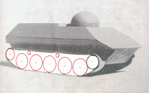
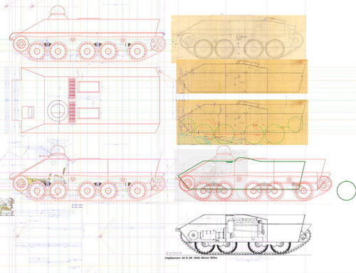
I wanted to see how the 38 running gear fitted the wooden model. Constructing the running gear to scale, converting it to an image and then superimposing it over the model image and transforming it produced a really good fit. A lot better than I thought.
. 0313DEC5-0EF2-477A-A33A-B86ECFD15F9B.png
 
Last edited:
Ok, I still failed to make sense of the engine placement event after reading the translated pdf. It talks about an "underfloor mounted engine" below the fighting compartment - I am quite skeptical if the whole fighting compartment is even enough for the engine even without the turret.

I think the Saurer APC does shed light on how the engine might fit:
View attachment 619490
With the engine offset to one side, adjacent to both the fighting compartment and the driver's compartment.
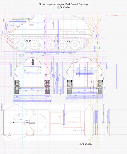
I have finally created scaled drawings of the vehicle in the AFV News and German articles. I think I can provide some illumination on the issue of the engine (motor) location and other issues.
Please note, the drive shaft, gearbox and transmission layout has not been updated in the article page. The revised layout is in the separate drawing with all the scaled dimensions. Now CORRECTED.
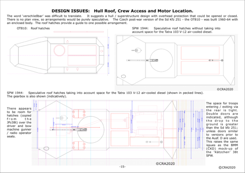
As you can see, by sticking to the original drawing it possible to provide the W1807 arrangement and forward access hatches. Access via the rear is tight, but no different from the BMM ‘Kätzchen’ 38(t). That’s a whole other issue of its own. Something I’m also working on.
Sorry, but I think the Shapeways model is unsustainable. There would not be enough room for a Tatra 103 or a Praga NR to fit alongside the turret.
Also, it needs to be born in in mind the evolution of performance from motors (engines) over time. What was achievable in the late 1950s was not possible in the mid-1940s. 437176AA-F2E4-42BD-A8DF-33704271FC71.jpeg C9AC6978-2568-42F5-8A9E-8CEC21BD5975.png B2A363A9-3EF6-4561-A75F-A337FFF01468.png 7556137D-3C8B-4C9C-BB50-2ED296346DAD.png
 
Last edited:
"underfloor mounted engine" below the fighting compartment
IIRC French wheeled vehicle, Panhard EBR, has engine (opposite-piston, sort of suitcase-shaped) located below its turret, so one might take a look at its drawings
And by the way, I would also suggest taking a look at Saurer 4K-3H prototype, which for some reason (related to gearbox or suspension, I guess) has floor of infantry compartment located like feet or two away from actual bottom of the hull
Continuing from my last post (here).....
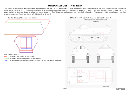
Your image of the rear of the Saurer-Werke prototype 4k raises the issue of exit / entry from the SPW shown in my drawing and the wooden model.
It would require rear doors similar to Sd kfz 251 before Ausf D. It was a complicated hinge arrangement. Ausf. D simplified that a lot. Considering the author of the German sketch had doubts about how he remembered the vehicle rear, I drew an alternative with an Ausf. D arrangment. F92F7D8F-EA5A-4B68-A3F1-EB2DC4A41891.png
 
Last edited:
PanzerKampfwagen 38(t) Variants by David V. Nielsen has photos apparently.
Just bought a 2nd hand copy. The photos are of the APC version of the Marder Ausf M. Never went beyond mock-up / prototype. The compartment is ‘perched’ on the back of the vehicle. Looks vulnerable. Many photos are excellent quality. Inside front cover has sections of the 38(t)n.A. Only plans in the book are the Pz 38(t)n.A.
Nothing on the SPW.
 
Last edited:
Here's a drawing of Schützenpanzerwagen auf 38 (d) from AFV News 1974. Looking for a better source.
I understand, but the problem with that ifv drawing is that it leaves no room for the engine (or at least I cannot see a place to fit one).
You cannot fit it beneath the glacis beside the driver because the radio operator and the loader in the fighting compartment is in the way; you cannot fit one in the infantry compartment becasue then you don't have space for all 8 crew members.
The only compromise I see logical is this:
View attachment 617049
It seems much more plausible as to the placement of the engine - eliminate radio operator and loader, removing the larger two-man turret and replacing it with a smaller one-man turret armed with MG 151/20, the turret itself offset to the driver side, making room for the engine placed at the right of the driver.

There is a Russian interpretation similar to this:View attachment 617051
However, this is a direct contradiction to the original German source:
"In late 1944 a specification was issued for a fully tracked personnel carrier based on a lengthened 38 (d) chassis. By adding a fifth road wheel, the length was increased to 6.2 m. The armour was 30 mm at the front and 20 mm on the sides. The vehicle was designed to carry a hemispherical turret with a dual-purpose 2 cm gun and have a crew of four. It could carry eight men in its rear section. Its weight was planned to be 12 tons and the maximum speed of 30 km/hour with a range of 200 km. Only a mock-up of this vehicle was built."
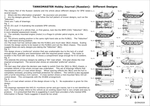
Working my way slowly through the Tankomaster articles on SPW designs.
Since you published the later 5-wheel design, I’d like to ask for yours and anyone else’s help / comments on the following ongoing work.
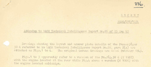
I purchased a number of scans from the Tank Museum of various BAOR Technical Intelligence Reports; in particular, Report No.26 (26 August 1945) (Tank Museum reference E2013.421) about the PanzerJäger 38D. It includes drawings of the W1806 and W1807 versions that you should have seen referred to before. These reports were produced by BAOR HQ and are considered secondary sources, because they are not original German documents. I don’t know if the originals exist anywhere.
These particular drawings are not totally accurate, but do contain lots of dimensions. Most of these appear accurate and allowed me to redraw them more accurately. No doubt people like Hilary L. Doyle would have used these in producing his drawings.
This has been my main source of data for the 38D chassis.
I am in the process of trying to produce scale drawings of the design shown in the TankoMaster article you published on this website.
Whilst, at first glance, it looks the best design; many issues have arisen.
Assuming this was a genuine wartime design, I’m finding a lot of questionable results.
W1807:
Hilary’s drawing seems to either match the body or the running gear; not both. In any case, the engine compartment is shown further aft in the TankoMaster drawing.
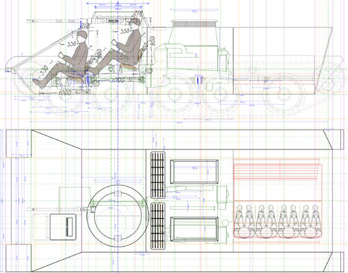
Headroom: I am having great difficulties reconciling a scaled driver and seating position with the scaled hull dimensions. I’ve done research into human ergonomics to check a number of sources and believe the human outline is a reasonable representation.
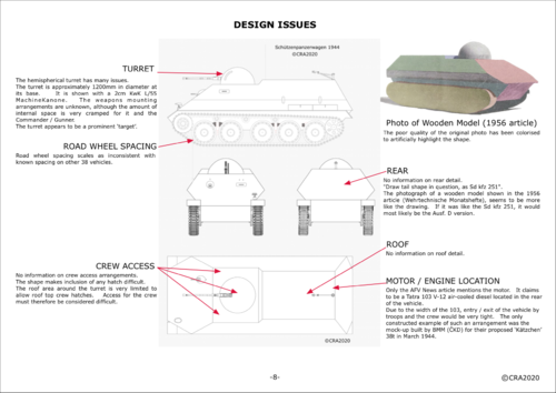
Turret: It’s presumably supposed to mount a 2cm Kwk 38, but there isn’t enough room. The largest turret diameter that can be fitted is ~900mm, whereas a turret mounting a 2cm Kwk 38 would require a minimum of 1200mm. Does anyone have any dimensioned drawings of such things?
I intend to produce an additional drawing containing reconscilliations, eg with a 1200mm diameter turret.

A comments and thoughts would be gratefully received.

3A7B0387-D61E-4FA7-99CB-9DC5EDA76279.jpeg
 
It is no doubt, a tough nut to crack, more so that even at the time nothing was fixed in stone as far as I know and there was room for a lot of change. The 38D hull would have made a better start point than the 38t for many reasons but what you are doing here is fantastic. I await update with a fair bit of anticipation, this is going quite a bit further than anything I have seen so far. I hope it does not dishearten you into giving up.
 
It is no doubt, a tough nut to crack, more so that even at the time nothing was fixed in stone as far as I know and there was room for a lot of change. The 38D hull would have made a better start point than the 38t for many reasons but what you are doing here is fantastic. I await update with a fair bit of anticipation, this is going quite a bit further than anything I have seen so far. I hope it does not dishearten you into giving up.
Many thanks. Disheartening.....No...not at all.
I just wondered if anyone had any thoughts on the scaled design so far, compared to the difficulty I’m having with the ergonomics.
It’s quite clear that taking the TankoMaster drawing at face value means the W1807 design has been modified by moving the engine compartment further to the rear. I have concluded that if a turret capable of mounting a 2cm Kwk is mounted, then the engine compartment will have to go further to the rear again. This is why I spent a lot of time trying to find dimensioned drawings of the Hangelafette turret and failed. I wanted to get the turret ring diameter and detailed plans of the gun mount. The Hangelafette is too large as it stands. The Schwebelafette is also too large. I then had to find any small turret mounting an equivalent weapon. This led me to the post-war Hispano-Suiza HS30 vehicles. Again no dimensioned drawings can be found. I’m not able to travel, so visiting the Bundesachiv or other places is out of the question. The HS30 turret has an outside diameter of 1200mm and the inside clear diameter is ~940mm. The German military have ‘ had a preference for 2cm Machinenkanone. I’ve even looked at German aircraft turrets to see if there is any useful information.
The other issue is the drivers position. I think it would have to go further backwards. Also the commanders (turret gunner) seat would have to go further back so that he did not kick the driver in the head. People don’t seem to think of these things, especially those interested in alternative designs. I won’t get started on that!
Have you looked at the Valka website and registered to see what I have posted there? There are 16 pages so far. If yo haven’t, it would be worth your while.
I’ve attached a page from my series to give you a glimpse of what the TankoMaster articles contain. I’ve actually finished looking at the first design. It’s basically using the Pz38(t) chassis. 8668C4A3-F7DC-48BF-8F1E-2E09BBC672DF.png
 
Last edited:
Personal experience of armoured vehicles leads me to the conclusion that being kicked in the head is not something designers are too worried about. Chieftain gunners had a backrest but it was often omitted to give commanders a bit more space. Essentially our backrest was the commanders shins and I got more than a few bruised kidney's. I have some diagrams of the E-25 hydro-electric gearbox that might have been a possibility, I got them from the Tank museum if you are interested?
 
Personal experience of armoured vehicles leads me to the conclusion that being kicked in the head is not something designers are too worried about. Chieftain gunners had a backrest but it was often omitted to give commanders a bit more space. Essentially our backrest was the commanders shins and I got more than a few bruised kidney's. I have some diagrams of the E-25 hydro-electric gearbox that might have been a possibility, I got them from the Tank museum if you are interested?
That doesn’t surprise me. A useful bit of personal experience. I’m always open for new information. Thanks.
 
There is a better illustration for dimensions but I cannot find it right now. I am having difficulty, the pictures are tiff and not recognised. I'll find a way to do this and upload later today or tomorrow.
 

Attachments

  • Argus Installation.jpg
    Argus Installation.jpg
    160.3 KB · Views: 172
  • Suspension Unit Diagram - butnotreally.jpg
    Suspension Unit Diagram - butnotreally.jpg
    141.8 KB · Views: 161
There is a better illustration for dimensions but I cannot find it right now. I am having difficulty, the pictures are tiff and not recognised. I'll find a way to do this and upload later today or tomorrow.
Thanks very much. Don’t worry, I think I may already have versions of these. I’m restricting myself to the Czech / BMM / Alkett 38 type chassis for the foreseeable future.
Amongst all this l’m also delving into the ‘Kätzchen’ 38(t) - the one they made a mock-up of and photos widely published. Just wish somebody had found looking down inside, instead of through the back door.
 
Personal experience of armoured vehicles leads me to the conclusion that being kicked in the head is not something designers are too worried about. Chieftain gunners had a backrest but it was often omitted to give commanders a bit more space. Essentially our backrest was the commanders shins and I got more than a few bruised kidney's.
You maybe just the person to help......
I’ve ‘thrown’ together some illustrations concerning the seating arrangements for the driver and commander / gunner.
I’d very much appreciate your comments.
The driver vision device seems far too low. I’m not happy that the drivers head is touching the roof. I’m wondering about the accuracy of the TankoMaster drawing. Maybe the hull is too low??? See 2nd sketch.
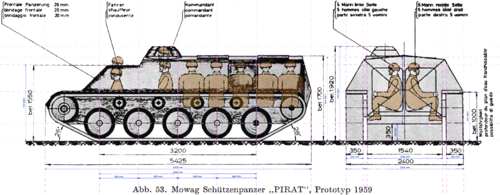
Since then, I checked out plans of the Swiss Pirate prototype 1959. It seems the height of the hull is very similar. It’s the ground clearance that’s a lot different. Conclusion: the driver sighting device needs moving up the glacis plate to position similar to the JPz38(t). This was a useful check.
7ED70FB5-29A5-4A1D-ABC6-081D877D0990.jpeg
95E63E1E-A03B-4B84-B087-75FA16FF5CE5.png
 
Last edited:
Something to consider is the problem of different driver physiology, no two drivers will be exactly the same. Does the drivers seat have an ability to adjust seat base height? Allowing for the demographic you are taking your recruits from you will accept a certain amount of height for different drivers. When you cannot change the height of the vision block, you can change the height of the seat base.
 
Something to consider is the problem of different driver physiology, no two drivers will be exactly the same. Does the drivers seat have an ability to adjust seat base height? Allowing for the demographic you are taking your recruits from you will accept a certain amount of height for different drivers. When you cannot change the height of the vision block, you can change the height of the seat base.
I’ve taken the drivers seat from the JPz38(t) "Hetzer". It almost certainly has a means of adjustment. Maybe someone who has access to a preserved vehicle could check that. I have not made up the human shapes. I’ve used published ones, preferably with dimensional data.
What I’m doing here is probably a classic reason for not working things out on a forum. I’ve now discovered - almost as a result of what I am doing (and contradicting myself) - is found that the SPW under discussion above is too high off the ground, by 65mm! Fortunately, lowering the hull doesn’t mean I need to alter the suspension - phew!
Back to the point. I think the ‘Pirate‘, etc means my hull heightening was a false alarm. I think the vision device is probably similar to the JPz38(t) in height position and should solve the issue.
Sorry, this was a lot of thinking aloud. It was probably worth it and you have helped. Thanks.
It must be incredibly cramped in AFVs.
 
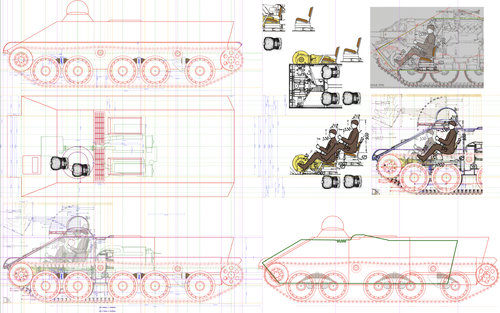
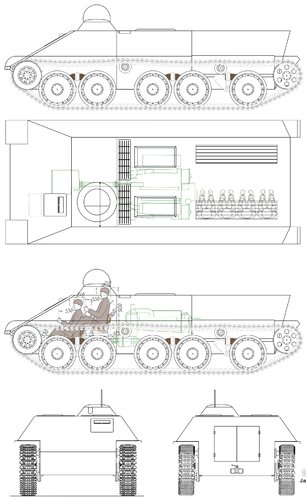
I’m posting a preliminary set of drawings for the SPW 38D, based on the TankoMaster article.
Please note the lack of armament. I have real problems with the turret size and a suitable weapon. More on this later.
Copyright CRA@2020.
6C8BFF84-38CA-4053-BD70-2CE409F4E63B.jpeg
 
I’m posting a preliminary set of drawings for the SPW 38D, based on the TankoMaster article.
Please note the lack of armament. I have real problems with the turret size and a suitable weapon. More on this later.
Copyright CRA@2020.

Very interesting indeed, thank you!
Two questions/remarks: (1) turret (or rather cupola) seems to be unrotated - there is no space for the commander to turn with the turret/cupola, (2) what is on the right side of the vehicle's front?
Thanks very much.
Turret: As I said previously, it’s a problem. The turret is drawn facing forward without any armament.
You raise an interesting point about the commander / gunner and rotation. Hadn’t thought of that. It just adds to the problems about the turret.
Right of front: Drivers vision port set in what might be a hatch(?). It’s on the TankoMaster drawing, but (impossibly) lower down the hull.
The design looks, on face value, like the best of the SPW designs; it does have this major problem with the turret.
The AFV News design has a unique(?) hemispherical turret, but at least there’s room for it / 2cm Kwk 38 / rotation.
The TankoMaster design has a rare turret shape for the time. The nearest I’ve found is the Rheinmetall / Porsche design on the Porsche Type 255 project.
I’ll be posting more about turret issues. Still drawing some of the stuff.
The nearest turret with 2cm Kwk 38 appears on some kits; eg Amusing Hobbies Jagdpanzer E100. Where did that come from??? Fictional? 9127C6A1-697C-48E5-810A-0915DFE31C50.jpeg
 
Last edited:
Conundrum / Enigma.........
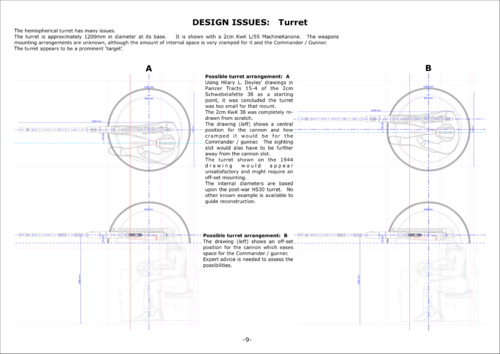
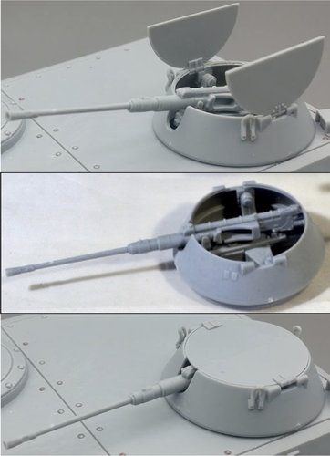
The turret:
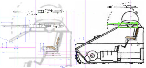
1st image (left) - enlarging the TankoMaster drawing so that the turret matches the Rheinmetall-Borsig (Porsche?) turret. The seat is for scale reference.
1st image (right) - at scale, showing the MK 108 in the turret (would it really fit???) and MG 34 above it (a definite fit, but very under gunned). MG 34 modified from Hilary L. Doyles’ drawing. Hope you don’t mind Hilary.
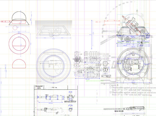
2nd image - shows the scaled turret, the Rheinmetall-Borsig (Porsche?) turret, MK 108, MG 151/20 (HLD) With scaled dimensions - thinking out loud.
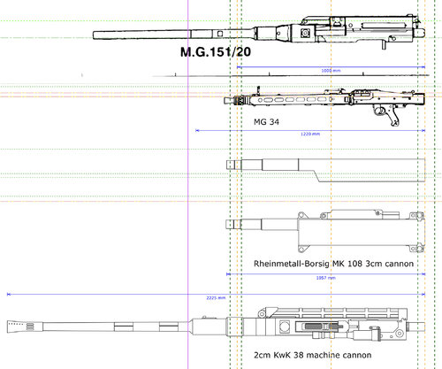
3rd image - comparison of weapons to scale (1st 2 HLD).
Beyond this = ‘brick wall’....... 22944857-EF14-4164-B364-A9F8EAA50822.jpeg 67533193-1552-4B66-A423-8AD71131D0BA.jpeg 15F84C42-34F6-4A55-A68D-540C86856030.jpeg
 
Last edited:
What follows is speculative thinking out loud. What would be needed to make the turret work? The following inspirations:
- the known Rheinmetall-Borsig turret for the MK 108
- work done on the hemispheric turret for the AFV News design
- the Amusing Hobbies cupola turret - where did they get that (‘idea’) from?
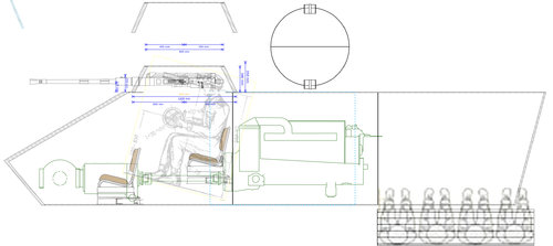
The following combines elements of all these and mounts the 2cm KwK 38 that seems to be the preferred Wehrmacht option. It resulted in enlarging the front compartment to accommodate a 1200mm outside diameter turret. This gives room for the commander / gunner to rotate freely without being impeded by the driver. The motor compartment has had to be moved further aft. The troop compartment becomes smaller and accommodating 8 soldiers would be cramped. However, there is scope to lengthen the hull slightly without interfering with the overall length and running gear to compensate.
I’ve refined the hull and turret with speculative armour thicknesses, based on the PanzerJäger 38D information in the BAOR Report. 8mm thick horizontal surfaces as in the report. The hull front and turret wall are 40mm thick.
Comments and thoughts are most welcomed.
@CRA2020 interim drawing.
EE51A17E-D0E3-4F92-BD27-5B8A35040DEB.jpeg F7A488BD-D913-4111-B403-773DC0F81251.jpeg
 
I think that gunner had his head not inside the gun turret
but seated next driver and operate via periscope the Gun
similar to Jagdpanzer 38
 
I think that gunner had his head not inside the gun turret
but seated next driver and operate via periscope the Gun
similar to Jagdpanzer 38
Hi,
Could you please give more details about that? Are you thinking about the remote control MG mount on the JPz38(t) "Hetzer"?
If so, I’m not aware of any remote control 2cm mount, other than on aircraft.
The 2cm KwK 38 uses clips of 2cm rounds and is not belt fed like the MG34 (ie the remote mount on the JPz38(t). It needs quick access to reload clips. I think the radio operator on this SPW would also act as loader. The gunner is also the vehicle commander.
 
Last edited:
Hi,
Could you please give more details about that?

looking on picture were the gunner head inside Turret
it quite dangerous near the 2 cm KwK 38 Gun, if something goes wrong could ripp his head off.
"Remote control" is here a simple mechanical system, that allow the gunner to operate from save distance just like in the JPz38(t)
view is give by Periscope installed in Turret or other wise.
 
Have a look at this video. You get some idea of the proximity of crew and effect of recoil / firing gun.
and....
and....
Quite a lot of changes would obviously be needed to allow one-man operation.
If my drawing is misleading - my apologies. The commander / gunner is sitting to the side of the gun. The sight is not attached to the gun, but mounted in parallel. You should look at Hilary L. Doyles Panzer Tracts 15-4. A very important source of information and one of the more recent publications in the series.
Hope this helps.
 
i that case i recommend to look into turret of "Schützenpanzers (kurz) Hotchkiss"


on Roof and back door on that Wood model
the german text describe the requirement of ABC protection for the Crew and soldiers onboard
This imply that must be a enclosed roof.

on back door from the form of the rear end, it look almost of the "Schützenpanzerwagen Sd.Kfz. 251"
then would look the door like that (right side)
Bundesarchiv_Bild_101I-209-0056-06%2C_Russland-Nord%2C_Schützenpanzer_mit_Besatzung.jpg


Oddly the german text, explain that the 1956 proposal has to be build simpel and easy.
what is in-contradiction with wood Model
in fact the later generation of Sd.Kfz. 251 had simplified flat rear and simpler Doors.

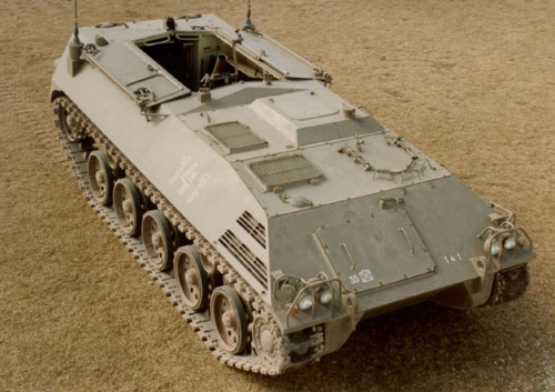
800px-Warsaw_Uprising_-_Captured_SdKfz_251_%281944%29.jpg
 
i that case i recommend to look into turret of "Schützenpanzers (kurz) Hotchkiss"

I’ve been working on that for some time. Bought several books covering the SPz11-2, SPz12-3 and Marder. The lack of published plans / drawings / blueprints on these vehicles is frustrating. Especially the Hispano-Suiza vehicles.
I have partially constructed a scale drawing of the HS30 turret, but very difficult. I have found useful photos of wrecks / restoration work showing the turret hole in the hull and the turret, but lack dimensions. I really want a cross-section through the turret (front to back) showing the HS820, seat and other internal details. I suppose the Bundesarchive might have something. I’m not able to travel, so that would have to wait for someone else to visit.
I have found some drawings of the SPz11-2, however, the turret is not exactly the same as the HS30 (SPz12-3).


on Roof and back door on that Wood model
the german text describe the requirement of ABC protection for the Crew and soldiers onboard
This imply that must be a enclosed roof.

Yes, absolutely. The author was thinkng of nuclear war - a recent concern for the time.


on back door from the form of the rear end, it look almost of the "Schützenpanzerwagen Sd.Kfz. 251"
then would look the door like that (right side)
Bundesarchiv_Bild_101I-209-0056-06%2C_Russland-Nord%2C_Schützenpanzer_mit_Besatzung.jpg


Oddly the german text, explain that the 1956 proposal has to be build simpel and easy.
what is in-contradiction with wood Model
in fact the later generation of Sd.Kfz. 251 had simplified flat rear and simpler Doors.

800px-Warsaw_Uprising_-_Captured_SdKfz_251_%281944%29.jpg
We agree. I’ve covered these issues in other posts.
You may want to register to view 21 pages I have written and so far posted on ArmedConflicts website:


The number of pages may eventually be more than 40 or 50.
Other vehicles I have been researching in connection with this are the AustrIan Saurer SPW prototype , that is basically a fully tracked Sd kfz 251; and the 4K series.
 
Last edited:
Could this be the best possible reconstruction??????
I am NOT happy with this. It does not feel right.
Why couldn’t the original design have had the turret mounted over the centre line, thus avoiding conflict with the driver?
Another issue is the cooling arrangements for the flow of air. This a whole other issue. 156B960C-28EB-4EEB-97A9-978648131782.jpeg
 
Last edited:
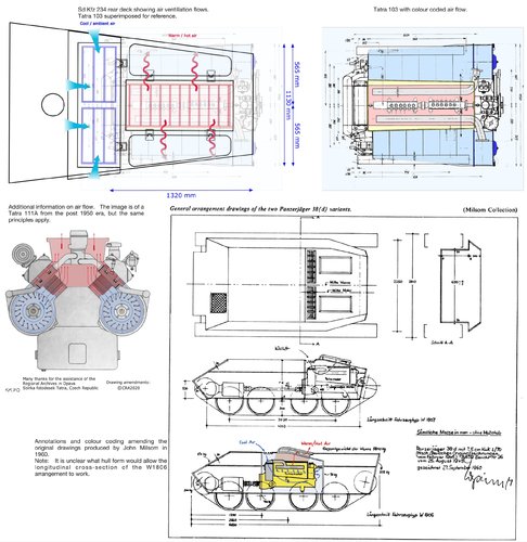
Tatra 103 / 111 V-12 air-cooled diesel.
It’s big - more precisely - wide. It’s the fans that give it the width. Width is a problem.
Also the air circulation to cool the engine (motor) - in particular, how the hot air is expelled from the engine room.
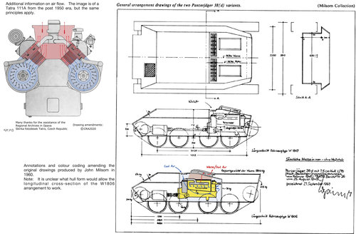
You should refer back to my 6 May 2020 post - the drawings on the right hand side of the image. Some come from a B.A.O.R. Technical Report in 1945 about the PanzerJäger 38D. The show the W1806 and W1807 arrangements.
The W1807 has the motor at the rear. I don’t see any issues with the cooling arrangements (ie the exit of the hot air).
The W1806 has the motor in the middle. Side and plan views show a ’flat’ structure on the hull top. This doesn’t seem to correspond with the side cross-section view that shows the raised hot air exit raised from the engine room. It’s confusing. That’s why I drew the last SPW with a raised ventilation structure. I’m missing something. Can anyone help?

images below: (apologies - they are not attached in order)
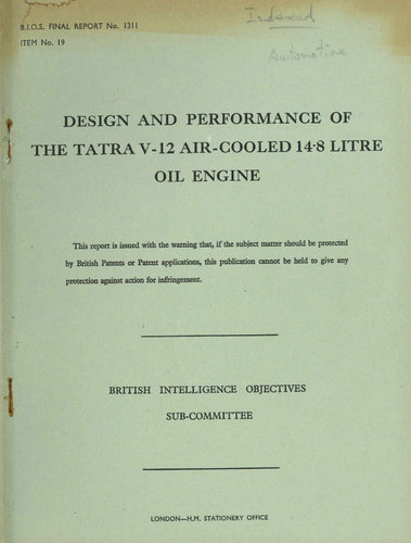
- Cover of a B.I.O.S. Report on the Tatra a engine / motor (one source of information).
- An extract from that report about cooling fans.
- An amended and colour coded version of John Milsom’s 1960 drawings. He almost certainly based these on the same B.A.O.R Technical Intelligence Report (see top part of one of the pages for reference). The reference immediately below is the catalog reference for the Tank Museum, Bovington. Useful, if you want to buy a scan of the document, including drawings.
E2013.421Panzerjager 38 (d)5623.438.4Panzerjager 38 (d)
My annotations to John Milsom drawing:
— light blue = cold or ambient air drawn into engine room, presumably by the 103 fans
— dark blue arrows = general flow of ambient air; drawn into the impeller fans; down the casing and pushed around the cylinder heads (which have cooling vanes)
— red arrows - direction of warmed / hot air from the cooling process up into a separated enclosure that ‘funnels’ the hot air to the exit vents. This is where I have problems with the way they are drawn in the report.
- Plan view of the Tatra 103 (thanks to the Tatra Truck Archives for providing me with a scan of the motors general arrangement with dimensions - this was a one off help)
—I have made some improvements to clarity and added the colour coding. This corresponds with the earlier description, except for:
— yellow = surround of enclosed space for venting hot air (on the Sd Kfz 234, a cover is attached to the hull top to contain the hot air). Presumably, the force of the fans pushes that hot air out through the top of the roof.


EA5652CB-949B-4C9C-A17F-396A38DCB14D.jpeg


C85E307B-BFB5-4833-BAB2-1B66DA24469D.jpeg 40B2E43B-A473-40D3-BAEC-5DC8F9D4367A.jpeg View attachment 635208 C268F5F5-74AF-469A-B67F-5C9679B7BB59.jpeg
 
Last edited:
........and just how noisy and dirty were Tatra 103 / 111......Exhaust smoke, not the hot air from the engine.
some videos to provide an idea...
1st: post-war T111 old truck
2nd: WWII footage - a few scenes show the clouds of exhaust smoke.
 
Last edited:
Very good stuff you are producing here. I would expect the larger engine to go with a hull extension otherwise it would not be required when the gun of the SPG is removed. The hull extension would also make for a more versatile gun carriage and ammunition carrier.
 
I may be a bit late to the party, and I must say bravo to SPW for the work in fleshing out this lost concept, but may I offer another angle? When I see the turret, I get the impression something more along the lines of what we see on Porsche's Light Tank 245/255 or the Entwicklungsfahrzeug E-25, as being more appropriate, especially given the size/space constraints. After all, considering this concept never went beyond a model (I have yet to find proof of a fullscale mockup), it's entirely possible that this problem would itself be fleshed out like what this thread ultimately ended up doing. Of course, this does not solve the problem. Truely, something akin to the Rundumfeuer MG-34 may prove to be the best option available in making this concept feasible.

typ255.jpg
 
Fantastic work SPW!

I have one question/observation to make though. The drawing cropped below ; C268F5F5-74AF-469A-B67F-5C9679B7BB59cropped.jpeg
seems to be related to the vehicle with the engine in the right rear of the fighting compartment. As the APC would be lighter than the SPG the existing suspension would surely cope with the weight of even a stretched hull. Returning to the capacity for 8 troops mentioned earlier it wouldn't take much to lengthen the hull to allow 3 plus 5 from 2 plus 4. Indeed W1806 appears to have the hull needed. This could then suggest that the heavier 5 wheel version with turret was a follow on development which ended with the Post-War vehicles.
Apologies if this is seen as the ramblings of an idiot but please feel free to ignore me.
 

Similar threads

Please donate to support the forum.

Back
Top Bottom