- Joined
- 25 July 2007
- Messages
- 4,299
- Reaction score
- 4,195
Hello. How can I read this patent?
Search: Brevet n°729.568, 26 juillet 1932, Robert Sauvage, Roland Payen

Hello. How can I read this patent?
For some reason, I can't find exactly the patent. I found an article about Roland Payen's planes.Search: Brevet n°729.568, 26 juillet 1932, Robert Sauvage, Roland Payen
Thank you very much.Here is this famous patent:
It was supposed to fill the voids of the fuselage with helium and hydrogen... A strange decision.Here is this famous patent:
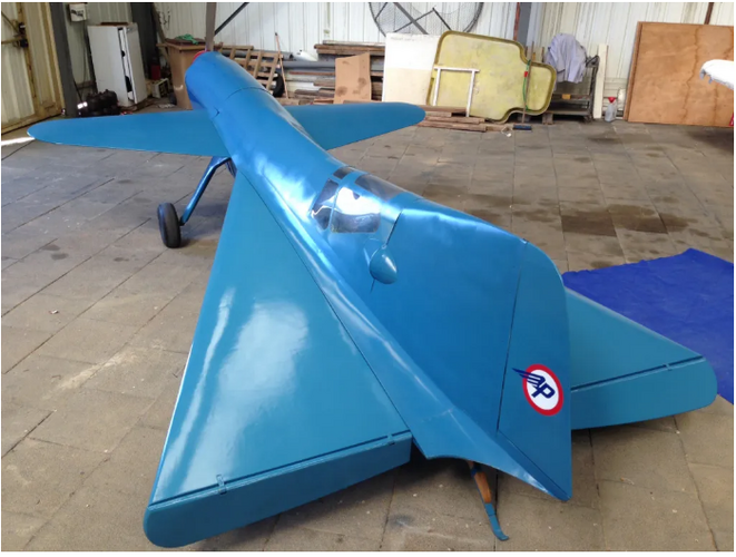
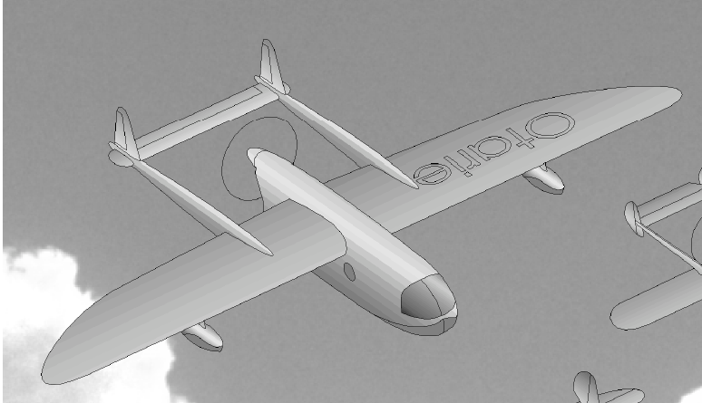
Pa.100 replica not flyable. Visible at Musée Delta (Athis-Mons) ...

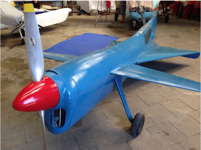
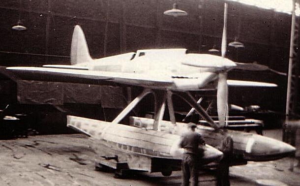
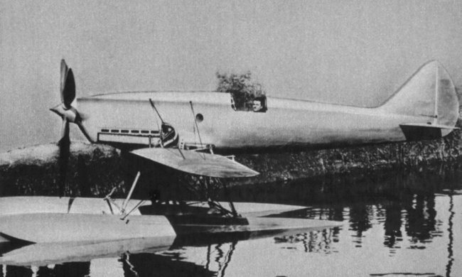
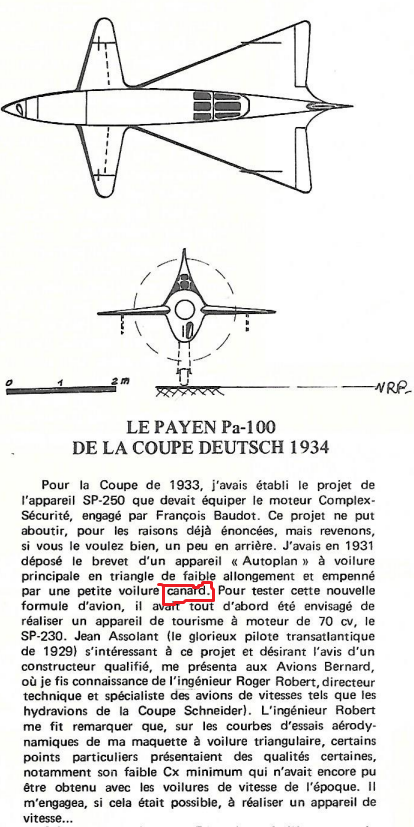
Because of the engine which hides it, the profile drawing does not allow us to see what is the exact width of the fuselage in its highest part.I have a question about the SP.230 project. I looked at its dimensions and noticed one strange thing: the width of the fuselage in the cockpit area is 50 centimeters at its widest point. Maybe I'm wrong, but it's kind of weird. Could this project have been a scaled-down layout?
That is, it is impossible to use these drawings and drawings from the patent without alterations. Did I understand correctly? In order for the drawing to make sense, is it necessary to expand the fuselage to an acceptable width with unchanged wings? Or the dimensions themselves in the drawings are incorrect and it is worth starting from the size of the motor (the diameter of the motor is 940 mm).Because of the engine which hides it, the profile drawing does not allow us to see what is the exact width of the fuselage in its highest part.
In the same way, the top photo does not allow us to know whether the width of the fuselage, hidden by the thickness of the wing, corresponds exactly to that of the cockpit. Perhaps it is more important.
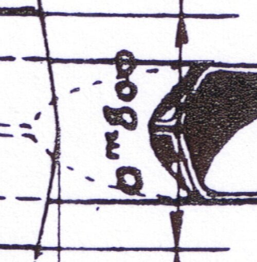
In any case, it seems that the builders were instead considering a width of 80 cm (even if it is possible that, after the fact, an "8" was drawn over a "5" on the drawing).
Perhaps also, if there were errors in the known drawing, the wind tunnel model (Photo from Fast Facts issue 65, page 21, Ferdinand C W Kaesmann article) corrected them.
Well, You definitely have the art of asking questions to which I don't have the answer...That is, it is impossible to use these drawings and drawings from the patent without alterations. Did I understand correctly? In order for the drawing to make sense, is it necessary to expand the fuselage to an acceptable width with unchanged wings? Or the dimensions themselves in the drawings are incorrect and it is worth starting from the size of the motor (the diameter of the motor is 940 mm).
I apologize for such questions. I understood your answer.Well, You definitely have the art of asking questions to which I don't have the answer...
I would say yes to the first question, yes to the second and no to the third.
But only the authors of the drawings could answer you correctly.
Maybe, one solution would be not to have a straight fuselage between the engine and the cockpit, but a fuselage which would widen between the engine and the cockpit, before this width naturally then decreases in both cases. Without guarantee...
short wingspan for racing planesWhat was the advantage of these weird Payen concepts ?
Aerodynamic drag...What was the advantage of these weird Payen concepts ?
What other than a canard ?Almost no visibility needed for take off and landing.
Is this a canard ?
Hello,
Well, here's an answer that's been making me think since I read it...Hello,
for me, this is not a canard:
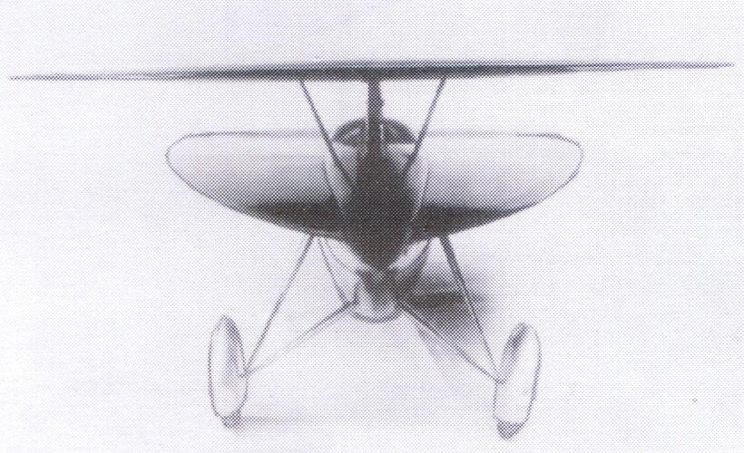
a canard is a plane with elevator control surfaces on the front. This is not the case of Payen concept. On the front, you have a small wing, with aileron control surfaces. The big triangle on the back side is a classic tail, with elevators. It is the same formula with big triangular tail than the one used by some pioneers and WW1 planes, such as Levavasseur Antoinette or Etrich Taube for example.
In aeronautics, a canard is a wing configuration in which a small forewing or foreplane is placed forward of the main wing of a fixed-wing aircraft

Roland Payen, while working in the design office of a certain Romulus Bratu, filed on November 13, 1931, with his friend Robert Sauvage, (industrial paints craftsman who provided him with financial assistance) a first patent of invention called “AVION AUTOPLAN” relating to a strange device comprising a large ogival wing (which will, from 1948, be called DELTA due to its similarity in shape with the 4th letter of the Greek alphabet) and front planes then called Machutes , later “Canard”.
Robert Gaillard cites the term only once (in Les cahiers du RSA, issue 226, March-April 1999, page 38, about the Pa.100):At the beginning of 1935, the pilot Jean Meunier, a former engineer with René Couzinet, resumed testing, at Etampes Mondésir, of Pa. 101. In March and April, several straight lines were flown, the plane took off in less than 100 meters with its Outurquin propeller, at around 160 km/h and at low incidence, the machute flaps being lowered by a few degrees.
It was on April 17, 1935 that the first real flight was made, without flight authorization being granted. This delta, which in fact is a "canard delta", was the first to fly in the world, despite the refinement of technical services, that this type of aircraft was contrary to the laws of aerodynamics "known to the era” and was of little interest.
It is a real delta-canard derived from the patent

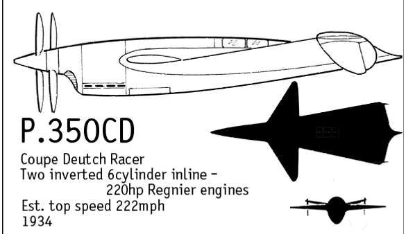
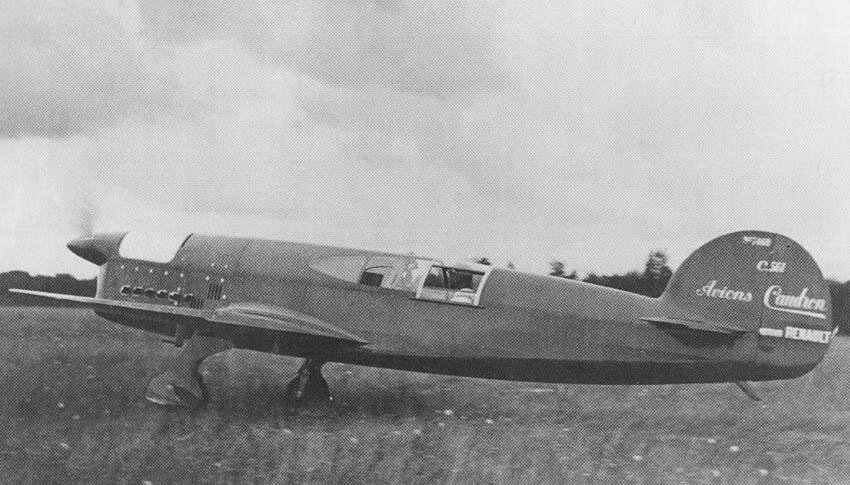
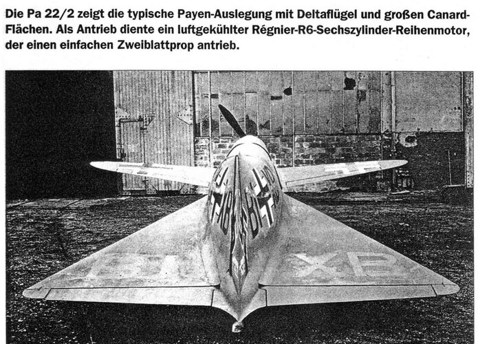
The Pa 22/2 shows the typical Payen design with delta wings and large canard surfaces. (photo bottom)
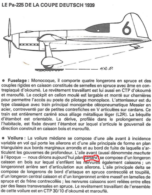
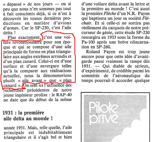
And (for the front wings of Payen aircraft in general)- "it is a revolutionary wing (that of the SP-230) for its time and which consists of a main wing with a triangular plan shape with rounded extreme angles and a canard plan. This one is of a surface and of a scale such that, comparing it to current achievements, we would rather call it "front wing" than canard plan" (Private Pilot n°47, January 1981, page 47. Photo bottom)
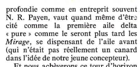
-"the front wing (which was not really a canard in the idea of our young designer)" (Pilote Privé n°89, June 1981, page 52. Photo bottom)

OK, thanks a lot for your answerI agree that there is no common definition of "Canard", so Payen's formula can be included or not, based on the sensitivity of each reader.
What I tried to underline is that the Delta part of Payen's "Flechair" planes is in fact an oversized triangular elevator, not really a wing as usually defined.
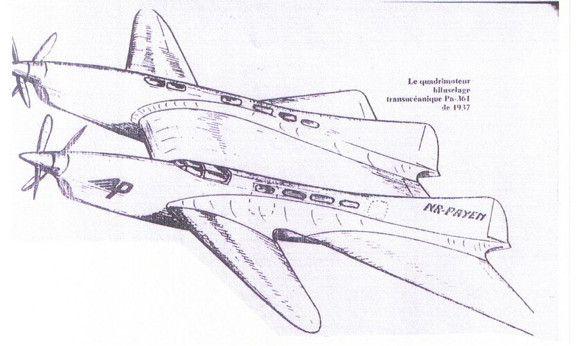
This one ?Perhaps a periscope arrangement was considered, per the famous trans-Atlantic crossing ??
Whatever, visibility etc resembles the infamous GeeBee racers too much for my peace of mind...
Please spell out explicitly and in detail exactly which definition of the term "wing" you are referring to here.I agree that there is no common definition of "Canard", so Payen's formula can be included or not, based on the sensitivity of each reader.
What I tried to underline is that the Delta part of Payen's "Flechair" planes is in fact an oversized triangular elevator, not really a wing as usually defined.