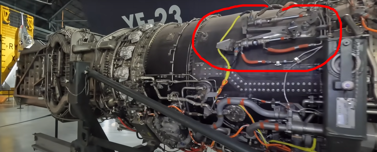
You are correct - the static display engine is the YF120. The engines installed in this airframe PAV-1 are the YF119 engines.

If you know anything about jet engines, at approximately 8:30 in the video on the right side of the YF120, you will see two separate variable vane actuators, instead of the single actuator that you normally see to move the core compressor variable vanes. I’m guessing that the vanes in front of the core mounted 3rd fan stage and the variable vane at the inlet of the core proper were controlled independently as part of the variable bypass control system.
Its surprising how swept those guide vanes are. They almost mask the fan face but perhaps that's just how they left at after mothballing?

Edit: Rewatching that footage the fan is quite visible. I have seen another picture of the YF120 where the fan is barely visible. WTFV
If by swept IGV you mean being angle to the rear from the OD to the nose cone, the F110 fan has a similar feature where the flow path is angled outward from the centerline, creating a bulged flow path from the outer inlet interface to the tips of the first stage fan blades. This allowed GE to fit a larger fan behind the F100 sized duct interface on the F-16. Don’t know if this has anything to do with increased fan size from the XF120 to YF120 - maybe the inlet ducts were already fixed in size before GE made this change. There may be other reasons for this feature.

As for not being able to see the fan blades thru the IGVs, remember that there are variable trailing edge flaps behind the fixed struts that are in a cambered position at low rotor speeds and move axial at high rotor speeds. On the production F119 they implemented a feature that moved these variable flaps into a axial position during engine shutdown to facilitate fan blade inspection and repair, at the request of he YF119 flight test maintenance team.
 
If you know anything about jet engines, at approximately 8:30 in the video on the right side of the YF120, you will see two separate variable vane actuators, instead of the single actuator that you normally see to move the core compressor variable vanes. I’m guessing that the vanes in front of the core mounted 3rd fan stage and the variable vane at the inlet of the core proper were controlled independently as part of the variable bypass control system.

u54trjhgdfn.png

Seems plausible.

Its surprising how swept those guide vanes are. They almost mask the fan face but perhaps that's just how they left at after mothballing?

Edit: Rewatching that footage the fan is quite visible. I have seen another picture of the YF120 where the fan is barely visible. WTFV

I suspect they do perform a masking function, the chord and camber of the fixed part appear unusually pronounced. The PoV shown in the video is not an aspect visible to any external sensor, it would be somewhere inside the duct wall with the engine installed.
 
I see they used my photos of the model posted here and no attribution. Now I know how Scott Lowther feels! :)

Enjoy the Day! Mark
There's a model on display in Saint Louis in a park. It's been posted in this site before.
 
Last edited by a moderator:
There's a model on display in Saint Louis in a park. It's been posted in this site before.
Yes, it was Mark who posted photos of it. They were used in the video without attribution or asking.
 
Last edited by a moderator:
There's a model on display in Saint Louis in a park. It's been posted in this site before.
Yes, it was Mark who posted photos of it. They were used in the video without attribution or asking.
Actually no the original poster of the pics was someone else who I don't recall but not this individual. The video perhaps but the original poster was someone else.
 
Going through Paul Metz’s book again, there are illustrations of both DP231 with F119s and DP232 with F120s, with the latter having a slightly “messier” trailing edge with an additional small serration notch. I believe there were some verbal statements that DP232 was less refined than DP231, and that both designs were “starting points” for the detailed EMD and production design that would go through PDR, CDR, etc, although the outer lines in the production design would likely be largely unchanged.

That said, Metz’s book also has pictures of a physical model of the EMD design alongside the DP110 (HSF) and DP117 (YF-23) showing the gradual evolution of the same configuration. The EMD model has a slightly different nose shape from the DP231/232 DWGs and also has the serration notch of DP232 which is a bit odd. I wonder if that model represents an earlier or later iteration of the design compared to the DWGs.

On the other hand, the book also has artwork of the production F-23 by Aldo Spadoni, and the isometric drawing shows a trailing edge that matches the cleaner one on DP231, and this further supports that the end goal is to have that cleaner trailing edge configuration.

On another note, the YF-23 Dem/Val presentation by Paul Metz and Jim Sandberg a few years ago indicated that PAV-2 with the YF120 attained a top speed of Mach 1.72, and this in fact may have been the top supercruise speed of the YF-23 (I recall that the test method was to use afterburner to accelerate to somewhere near the target Mach number and then pull the throttles back to mil and allow the aircraft to reach thrust-drag equilibrium, and this was reportedly around Mach 1.7 for PAV-2). It’s certainly noticeably higher than the YF-22’s Mach 1.58, although perhaps not as dramatic as some of the more hyperbolic statements over the years portray. That supercruise speed would only later be attained by the production F-22, which has a noticeably slimmer fuselage particularly at the aft (to be fair the YF-22 was also a much more immature design). In contrast, the F-23 appeared to have actually gained volume over the YF-23 while retain its area ruling, which not necessarily improving fineness ratio, would further help its endurance.
 
Last edited:
Actually, after some further reading, the EMD model is labeled as DP201, which would seem to predate the DP231/232 drawings submitted for EMD. @Ogami musashi pointed this out in another thread that the label also included “FSD” (full-scale development), which was an older term for EMD. In summary, DP231 is a pretty good representation of what a production F-23 would be like, with the usual caveat that minor changes are expected as the design goes through PDR, CDR, etc.
 
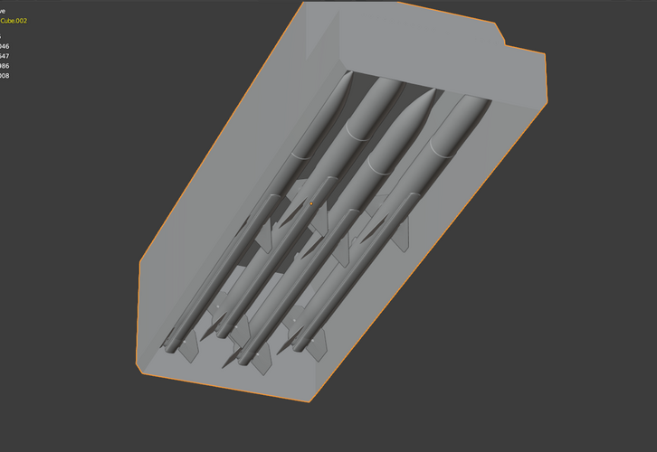
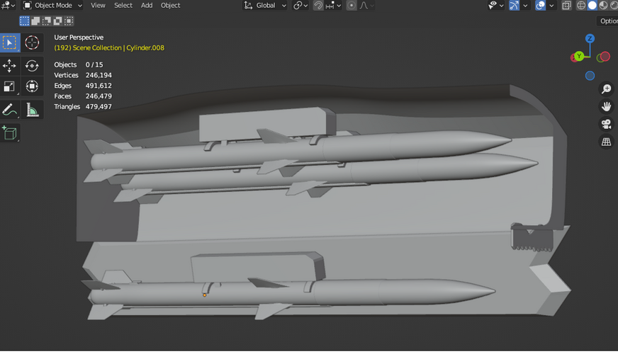
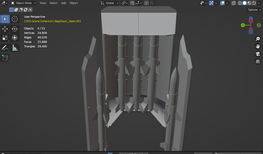
I was tinkering with Blender and decided to recreate the Northop patent for the vertically stacked missile system. I made an animation for the missile and didn’t bother making the ejection actuator move. This is scaled as best I can to the patent and it’s fit into the DP231’s bay although you’ll note I had to make some changes to accommodate it.

AIM-120 Vertical Launcher

Great work! Wouldn't it be more logical to use the earlier YF-23A DP117K weapons bay instead? The older design was in fact a tad higher if I remember correctly (the EMD F-23A DP231 having a tandem bay versus the DP117K single bay).

I made a rather crude drawing some times ago and the YF-23A bay could hold easily two stacks of four AIM-120 (A or B model) as per the patent drawing. Even three stacks, with small margin (to be verified by someone more knowledgeable than me) with a slightly smaller wingspan missile (the then secretly developed AIM-120C, or the AIM-132 ASRAAM which was supposed to replace the AIM-9 Sidewinder).

I'm glad you publish this because every time I see people arguing that the YF-22 had superior weapons bay capability, I think about this... If the Air Force hadn't rejected that launch system (for potential jamming issue) the choice in 1991 would have been between:
YF-22: six missiles (four AIM-120A or -B, later six -C models with the production F-22A, and two AIM-9M or two AIM-132 ASRAAM).
YF-23: eight missiles (eight AIM-120A or -B, and potentially twelve AIM-120C or a mix of eight AMRAAM and four ASRAAM).

I will try to dig up those drawings.
Well the problem is that I believe that some of those whom have corresponded with retired Nortrop engineers have said that they (Northrop engineers) stated that this launcher design was not what they were planning on using. It is possible they could've circled back to this or a similar design to meet the desire for 6 + 2 configuration. Personally I do agree with others that the weapons bay configuration is a weakness of the design, unless there is a launcher technology we aren't aware of. Its not so much the volume but there are a bunch of constraints that really limit how many AMRAAMs you can realistically carry. The biggest one being the relatively small doors. Notice too how no other designs have followed this approach. The F-35 being somewhat similar in that it too uses a deep bay design but this was mainly driven by the requirement to carry 2Klbs class weapons. Don't get me wrong, I love the F-23 as a design overall but it's weapons bay is a not a design strength.
 
YF-22: six missiles (four AIM-120A or -B, later six -C models with the production F-22A, and two AIM-9M or two AIM-132 ASRAAM).
YF-23: eight missiles (eight AIM-120A or -B, and potentially twelve AIM-120C or a mix of eight AMRAAM and four ASRAAM).

I will try to dig up those drawings.
Where did you get info that production f-23 would be able to carry 8 AIM-120A/B or potentially 12 AIM-120C?
 
Given that the chain driven AMRAAM launcher was patented, that probably tells you its unlikely to have worked apart from in pretty niche areas; e.g. really low g limit on release? Jamming? Different store loads?
 
Where did you get info that production f-23 would be able to carry 8 AIM-120A/B or potentially 12 AIM-120C?

Perhaps he's referring to The Drive article on the F-23's weapons bays? There's speculation in there about some extraordinary claims like this. I may be wrong but that article strikes me as if it's referencing this very thread. In the beginning there were similar extraordinary ideas for weapon load outs as there wasn't clear information on the actual clearances and other constraints. Ironically, there's that patent for the rotary launcher for folding fin missiles that would've allowed for 8 folding fin AMRAAMs in a MWB that is only a bit larger than the design we see in DP231. I think one of the draw backs is the folding fin AMRAAM itself as the USAF was against having two missile types on the flight line. They wanted to ease logistic burden and not have a ATF only variant.
 
Given that the chain driven AMRAAM launcher was patented, that probably tells you its unlikely to have worked apart from in pretty niche areas; e.g. really low g limit on release? Jamming? Different store loads?
I'm not convinced that because it was patented it was unworkable but there are certainly higher technical risks with this approach for sure. One area I would be concerned about is using a chain carrier for restraining the weapons. Even under normal flight loads there's going to be vibration that may damage the missile. Perhaps the carrier's "feet" have protective feet on them however. It does seem,however, to be a bit of a Rube Goldberg approach to missile stowage.

There are indeed other options that I could see as being possible but would also require some sort of weapon articulation to move to a launching position. In the end, I believe it's been stated by former program engineers whom members of this forum have spoken to that they stress its merely the starting point for FSD and the implication here is that there could have been a redesign of the bay/launcher designs. The challenge would be to keep it within a similar volume limit on the airframe.
 
Something like a smaller common rotary launcher but sized for AMRAAMs seems to make the most sense, but if you sketch it out then it seems quite a lot bigger than the available bay space.

Some articulating / rotating / translating launcher as you say may be more possible. I think this probably gets overly optimised for AMRAAM though and isn't as flexible for different weapon types.
 
I had mail exchanges with Aldo spadoni, which was the avionic engineer on the program back then, and he told me he saw no configuration with 8 clipped fins amraams, despite the fact that each day, even after the submission of the emd, you had a new iteration of the design each day. The reason is simple, the clipped fins amraam program was on hold at the time, and both the F-23 and F-22 were planned for 4 amraams A/B and 2 sidewinders. The difference is that the F-22 bay was more adaptable, while the F-23 was tightly knit for the requirements. We've been several here to toy with 3D models and CAD, and you always end up with the problem of the wing first bulkhead, that crosses the weapon bay and was made so as to leave just enough clearance for the amraams A/B, with their fins behind the bulkead. The consequence is that, when you go to clipped fins amraam, you gain zero space. So I am not sure you could have crammed in 8 amraams. The F-23 EMD was only the baseline, so changes would have been made to the weapon bay.
 
I had mail exchanges with Aldo spadoni, which was the avionic engineer on the program back then, and he told me he saw no configuration with 8 clipped fins amraams, despite the fact that each day, even after the submission of the emd, you had a new iteration of the design each day. The reason is simple, the clipped fins amraam program was on hold at the time, and both the F-23 and F-22 were planned for 4 amraams A/B and 2 sidewinders. The difference is that the F-22 bay was more adaptable, while the F-23 was tightly knit for the requirements. We've been several here to toy with 3D models and CAD, and you always end up with the problem of the wing first bulkhead, that crosses the weapon bay and was made so as to leave just enough clearance for the amraams A/B, with their fins behind the bulkead. The consequence is that, when you go to clipped fins amraam, you gain zero space. So I am not sure you could have crammed in 8 amraams. The F-23 EMD was only the baseline, so changes would have been made to the weapon bay.
I don't think 8 AMRAAMs, compressed carriage or not, was ever a formal requirement except at the very early in the program when they wanted 8+ 4 which was trimmed back as it was pushing the size way up. I'm guessing there was a informal requirement/desire to get to 6+2 which is what we got with the Raptor. Did Aldo ever state if they looked at 6 AMRAAM designs? 6 is even a challenge but is possible with some enlargement of the main bay vertically. You can get 4 AIM-120Cs (but not A/Bs) across the upper part of the bay. It is more of a question of how you get the outboard shots into a acceptable firing position.
 
YF-22: six missiles (four AIM-120A or -B, later six -C models with the production F-22A, and two AIM-9M or two AIM-132 ASRAAM).
YF-23: eight missiles (eight AIM-120A or -B, and potentially twelve AIM-120C or a mix of eight AMRAAM and four ASRAAM).

I will try to dig up those drawings.
Where did you get info that production f-23 would be able to carry 8 AIM-120A/B or potentially 12 AIM-120C?

As written above (maybe not clearly enough, sorry if that's the case), it's just some personal speculation based on the patent drawings and the available YF-23 demonstrator (not the more production representative DP231) technical drawings.
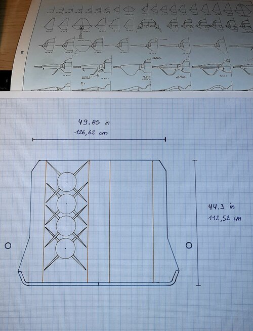
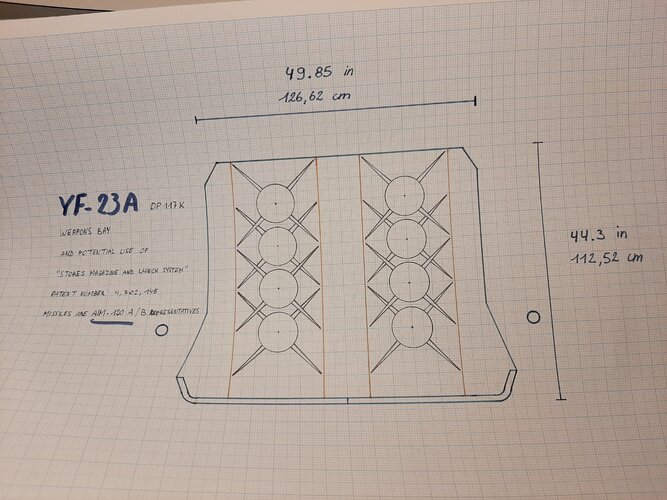
Couldn't find my old sketches so I quickly made those new ones (yeah on paper, I'm that old-fashioned o_O).

Two stacks of four AIM-120A fit, with minimal vertical margin (three stacks would probably be too cramped and conflict with the weapons bay corners). Replace them with newer Charlie model with reduced wingspan, and you can definitely - well, to me at least - add a third stack (with slightly better vertical clearance). Disclaimer: I known that "because it fits" doesn't necessarily mean it's usable/practical.

Please forgive this quick and dirty job. ;)

Note: for the AIM-120A stacks - including the patented launching system - I used ~40cm wide and ~110cm tall.
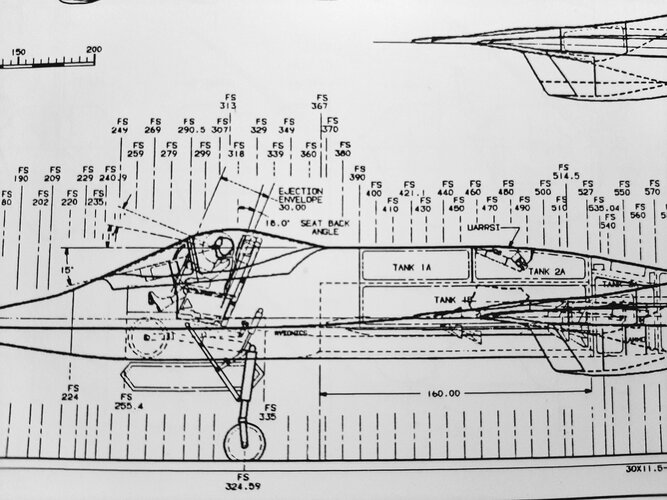
Weapons bay dimensions are from "Le Fana de l'Aviation" (March 2021) article about the YF-23, as noted on an original sketch from a Northrop engineer.
 

Attachments

  • 20221211_012951.jpg
    20221211_012951.jpg
    2.9 MB · Views: 231

As written above (maybe not clearly enough, sorry if that's the case), it's just some personal speculation based on the patent drawings and the available YF-23 demonstrator (not the more production representative DP231) technical drawings.
Couldn't find my old sketches so I quickly made those new ones (yeah on paper, I'm that old-fashioned o_O).

Two stacks of four AIM-120A fit, with minimal vertical margin (three stacks would probably be too cramped and conflict with the weapons bay corners). Replace them with newer Charlie model with reduced wingspan, and you can definitely - well, to me at least - add a third stack (with slightly better vertical clearance). Disclaimer: I known that "because it fits" doesn't necessarily mean it's usable/practical.

Please forgive this quick and dirty job. ;)

Note: for the AIM-120A stacks - including the patented launching system - I used ~40cm wide and ~110cm tall.
Weapons bay dimensions are from "Le Fana de l'Aviation" (March 2021) article about the YF-23, as noted on an original sketch from a Northrop engineer.

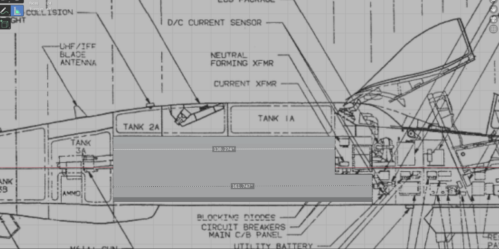
So I whipped up a very quick bay for the YF-23 based on the plans in Aerospace Review. I found I could fit 9 in there assuming a similar launcher technology as the vertically stacked patent. This also assumes that there is enough room for said launchers within the bay. But there is one big problem.... The bay is not long enough to carry AMRAAMs in this way. You could, theoretically, mount six since you can't stagger them.

There are other concerns however. One problem identified in Metz's book is that this tall bay configuration was concerning from a structural and load path perspective. Hence the shorter, round bays in the EMD submission.
 

Attachments

  • YF-23_bay.png
    YF-23_bay.png
    201.4 KB · Views: 219
BDF, I think we're using different references, maybe we should continue this via private messages? ;)

Sketches from the Northrop engineer in Le Fana magazine (not sure if I can share them here ?) do include staggered AMRAAM (with folding fins by the way). AIM-120 is 366cm long + ~32cm offset to clear the fins is 398cm. The weapons bay is 411cm long. Tight but it fits, at least on paper. No idea of that's sufficient for operationnal use.

I updated my drawing of the eight AIM-120A/B and made another one with twelve AIM-120C (or technically eleven and one AIM-132 ASRAAM for comparison).

The vertical magazine patent has been submitted/published between those of the DP86 (early ATF design with platypus nose) and the DP-117 (YF-23A). Each of those patents is in fact one year or two older, by comparing with now available published drawings. The more I look at it, the more I think the DP86/117K COULD have been designed around that vertical magazine idea. And the following is pure theory: as the idea was rejected (either by Northrop directly, or - as I've read several times - by the Air Force), this left Northrop engineers with a huge bay to work with, and no optimal arrangement. Again, pure speculation from me.
 

Attachments

  • 20221214_002459.jpg
    20221214_002459.jpg
    3.5 MB · Views: 189
  • 20221214_002507.jpg
    20221214_002507.jpg
    3.2 MB · Views: 186
Last edited:
BDF, I think we're using different references, maybe we should continue this via private messages? ;)

Sketches from the Northrop engineer in Le Fana magazine (not sure if I can share them here ?) do include staggered AMRAAM (with folding fins by the way). AIM-120 is 366cm long + ~32cm offset to clear the fins is 398cm. The weapons bay is 411cm long. Tight but it fits, at least on paper. No idea of that's sufficient for operationnal use.

I updated my drawing of the eight AIM-120A/B and made another one with twelve AIM-120C (or technically eleven and one AIM-132 ASRAAM for comparison).

The vertical magazine patent has been submitted/published between those of the DP86 (early ATF design with platypus nose) and the DP-117 (YF-23A). Each of those patents is in fact one year or two older, by comparing with now available published drawings. The more I look at it, the more I think the DP86/117K COULD have been designed around that vertical magazine idea. And the following is pure theory: as the idea was rejected (either by Northrop directly, or - as I've read several times - by the Air Force), this left Northrop engineers with a huge bay to work with, and no optimal arrangement. Again, pure speculation from me.

It's not clear which PAV these plans are for but they indicate that the bay couldn't even accommodate a AMRAAM in length except on the lower half. I double checked the scale to ensure it is scaled correctly. So that reference of yours is technically correct but there's no depth at all for AMRAAMs vertically. They can, however, fit 4 across staggered like the F-22 does, provided they're AIM-120Cs.


YF-23 bay quater view.png YF-23 bay side view.png YF-23 bay with AMRAAMs.png


Regarding the launcher technology, I haven't found anything definitive that the USAF didn't like the AMRAAM launcher design of the YF-23, just anecdotes. Metz's book states that the two bay design was driven by structural concerns and the desire to add more fuel and equipment volume. He did state that the single bay design had less than desirable weapons carriage options with the full finned versions and Sidewinder stowage on the doors which is considered less than ideal. It would be interesting to see what the stowage ideas were for the final design as they iterated after the formal submission.
 
Eureka!
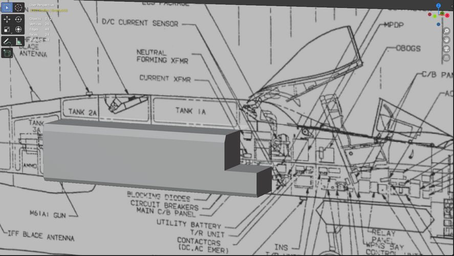
The weapons bay seen from the side is a rectangle. The avionic bays that made you think the weapons bay was amputated from its higher half are on the sides of it. :)
You can see the weapons bay contour superimposed to the avionic bay on the drawing you are using.

See this other one for clarity. ;)
Note that the weapons bay is completely extending in front of the tank 1A.
 

Attachments

  • 20221216_021036.jpg
    20221216_021036.jpg
    2.7 MB · Views: 226
Last edited:
Ah ok that makes more sense. That being said the plans I have do not show that at all and it's not obvious of the extent of the bay shape. Reworking my simple model it does not appear to me that one could get more than 9 in there realistically accounting for the launcher components. In the end though it doesn't matter as it was not considered sound structurally for a production airplane. At least with a production airplane with the same constraints desired by the design team and ATF SPO. It is crazy how efficient it is from a weapon stowage perspective.
 
I don’t take too much stock in the large single bay configuration seen in DP117K. Northrop themselves moved to a tandem bay which aside from flexibility improvements, also strengthened the structure.

Regarding the bulkhead interference in DP231, I think that’s an issue that would resolve itself as the design goes through full scale development and EMD. That said, without using some kind of vertical stacking launcher, I don’t think it’s possible for the EMD F-23 design to pack more than 5 compressed carriage AMRAAMs in the main bay, three on top and one on each door/hinge, while the F-22 can pack 6. The same applies for a mixed strike load with one JDAM or 4 SDBs, where the F-23 can pack 3 additional AMRAAMs while the F-22 can do 4. The problem with the F-23 isn’t bay volume, it’s that our missiles were never really designed around a vertically stacked launching system.
I tend to agree. There are some conceivable configurations which would allow 2 + 6, BUT they do require a bay redesign and would require a funky articulating launcher system to work. I suspect a bay redesign would be required in any case and there could be a launcher system that we aren't aware of/can't conceive. I think it's fair to say that the F-22 has a more flexible, lower risk bay configuration.

enhanced bay.png

Animation Link: Launch Sequence


Northrop design sacrificed some weapon flexibility for other attributes such as signature and range. I wonder how much of a problem, realistically, a more complicated launcher system would pose operationally. Certainly it could cause maintenance headaches if not designed properly. Perhaps weapon handling issues too.
 
Let me backtrack a bit by clarifying that while a vertically stacked or articulating system on the F-23 to enable the carriage of 3 AMRAAMs per bay may be complex and risky, I don’t think it’s entirely unreasonable. After all, this is what Lockheed Martin has proposed for the F-35 in the form of Sidekick to expand its AMRAAM carriage from 2 to 3 per bay. Of course, the jury is still out on whether or not it will be adopted and pass all the separation testing.
 
The missiles in the EMD are already stacked. You cannot fire the top one if the lower one is jammed. Aldo told me it was a compromise Northrop thought was okay considering the weapon bay doors were stealthier and, theoretically, more reliable that those on the F-22.
It seems to me the middle amraam on the F-22 is also stacked.
 
On the F-23, is the lower missile mounted on the door/hinge, or does it share the same launching mechanism as the top missile? When I say stacked, I meant that they're packed like a magazine where multiple missiles share the same launching mechanism. Contrast this to the current configuration on the F-35, where each missile has its own launcher. The middle missile on the F-22 has its own launcher, it's simply staggered in order for the fins to clear each other.
 
For what it’s worth, I think the F-22 with its 2+6 is more of an exception than the norm. Neither the J-20 nor the Su-57 can match its payload, and that’s with the J-20 sharing a very similar bay design.

The F-23 would have been perfectly ok with 2+4 or 2+5, whichever it may be.
 

Attachments

  • 9F7734FB-51D6-42D8-9618-3FCA39311989.jpeg
    9F7734FB-51D6-42D8-9618-3FCA39311989.jpeg
    395.8 KB · Views: 133
Last edited:
The plan for a production variant was 5 amraam with potential for 7 plus of course 2 winders.

To this day i think only 2 amraam have ever been fired by a single fighter.... sooo.... 6 v 5 really wasn't the deal maker for the usaf.

But 6 makes for better numbers at cope india.
 
Last edited:
The plan for a production variant was 5 amraam with potential for 7 plus of course 2 winders.

To this day i think only 2 amraam have ever been fired by a single fighter.... sooo.... 6 v 5 really wasn't the deal maker for the usaf.

But 6 makes for better numbers at cope india.

Interesting. Its very easy to get 5 AIM-120Cs to fit into DP231's main bay. Now I'm very curious about the 7 missile concept. My guess for the 5 shot configuration:

5 shot bay.png

5 shots vs 6 isn't a bad tradeoff for ~20% more fuel and better LO than the F-22 I suppose. I'm not an engineer but I always find comparing differing designs and their tradeoffs fascinating.
 
Let me backtrack a bit by clarifying that while a vertically stacked or articulating system on the F-23 to enable the carriage of 3 AMRAAMs per bay may be complex and risky, I don’t think it’s entirely unreasonable. After all, this is what Lockheed Martin has proposed for the F-35 in the form of Sidekick to expand its AMRAAM carriage from 2 to 3 per bay. Of course, the jury is still out on whether or not it will be adopted and pass all the separation testing.
To be honest I'm not sure, if USAF was indeed leery of a complex launcher system, why that was as bombers have had rotary launchers for years. So a single point of failure would indeed prevent any furthr weapon release for them. I will grant that a fighter is a much more challenging design between structural loads, bay acoustics, supersonic airflow and weapon release conditions. Perhaps TAC was a lot more conservative in their design requirements.

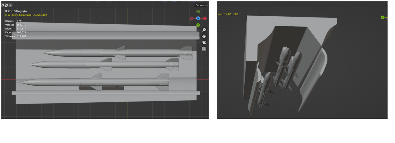
Are you sure about F-35's sidekick launcher? Its very difficult to tell from that low resolution CAD model image that's been released but from that I've seen it looks to me that the two upper bay launchers are fixed and staggered longitudinally and perhaps vertically. I haven't found a good cross-sectional drawing for the F-35's bay and had to rely on a old drawing of the mid bay I found on Aerospace web (which I'm not sure how accurate it is) to derive a simple model but this is my guess what SideKick roughly is:

F-35 sidekick.png

What I didn't try to create is a basically a dual launcher system that has one attachment point to the bay itself. Kind of analogous to the F-18's dual AMRAAM launcher with LAU-147s instead of rails.
 
I thought the 5 AMRAAM layout was two eject(?) launchers on the doors/hinges and 3 staggered on a trapeze that swung down and rail launched at a downwards angle
 
On the F-23, is the lower missile mounted on the door/hinge, or does it share the same launching mechanism as the top missile? When I say stacked, I meant that they're packed like a magazine where multiple missiles share the same launching mechanism. Contrast this to the current configuration on the F-35, where each missile has its own launcher. The middle missile on the F-22 has its own launcher, it's simply staggered in order for the fins to clear each other.
They share the same launcher.
 
The plan for a production variant was 5 amraam with potential for 7 plus of course 2 winders.

To this day i think only 2 amraam have ever been fired by a single fighter.... sooo.... 6 v 5 really wasn't the deal maker for the usaf.

But 6 makes for better numbers at cope india.
Do you have a source for that production variant plan?
Because that doesn't agree with what has been published in Metz book, neither was Aldo Spadoni told me.
 

Similar threads

Please donate to support the forum.

Back
Top Bottom