You are using an out of date browser. It may not display this or other websites correctly.
You should upgrade or use an alternative browser.
You should upgrade or use an alternative browser.
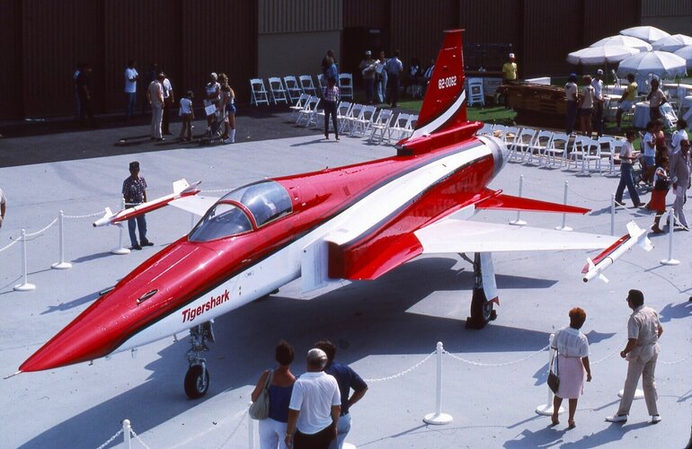
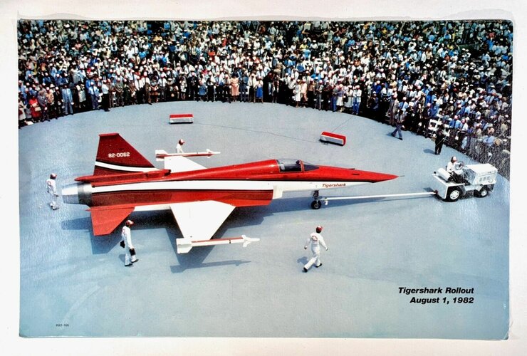
Northrop F-5G / F-20 Tigershark
- Thread starter hesham
- Start date
Scott Kenny
ACCESS: USAP
- Joined
- 15 May 2023
- Messages
- 11,531
- Reaction score
- 14,122
They hung most of it out the back.How exactly did Northrop manage to fit in an engine an entire meter longer in essentially the same airframe?
Basically off-topic, but a good excuse as any to post this image l had not seen before. There was a Naval F-5A or something similar that would have been a contemporary to Hunters and it is possible Sparrows were tested "on paper"...I remember reading a phrase a while back on adding a missile to another aircraft, cant remember offhand which and which but it went 'it was like adding an anchor to the aircraft'.......this could apply here.
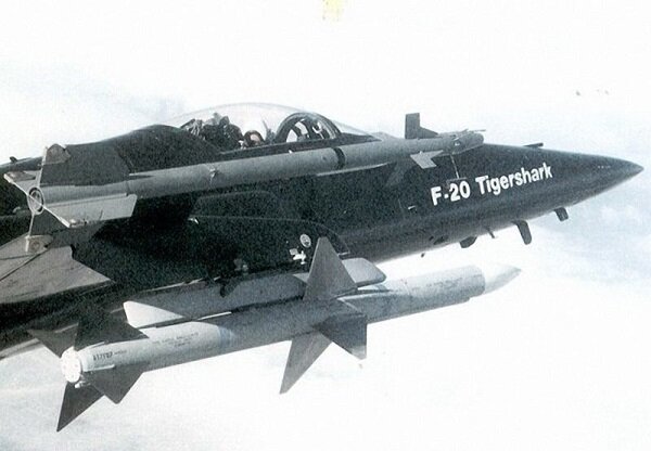
From:

The F-5G / F-20 Tigershark; Northrop’s Bane - Forgotten Aircraft - Military Matters
Northrop's F-20 Tigershark was an aircraft that seemed to offer everything that a customer could want. So what went wrong?
 militarymatters.online
"What went wrong" was essentially the US Air Force saw the Tigershark as a threat to F-16 production, and lobbied heavily against it wherever it was being offered, including foreign markets, even when directed by Congress to support the FX program. The more F-16's being produced, the lower the per-unit purchase price for USAF. I remember reading in the press back in the 80's about Northrop's frustration; whenever they'd go to a foreign buyer to show off the F-20, DoD, on behalf of USAF, would essentially tell them "Hey, you should buy F-16's. It's what we use". And foreign customers wanted what US forces were using. The answer to everything other than high end air superiority was some flavor F-16.Basically off-topic, but a good excuse as any to post this image l had not seen before. There was a Naval F-5A or something similar that would have been a contemporary to Hunters and it is possible Sparrows were tested "on paper"...
View attachment 736474
From:

The F-5G / F-20 Tigershark; Northrop’s Bane - Forgotten Aircraft - Military Matters
Northrop's F-20 Tigershark was an aircraft that seemed to offer everything that a customer could want. So what went wrong?militarymatters.online
Let Sir William explain what went wrong.

Uhm, yeah, the necessary translation. F-5A carried as heavy a weaponload as an F-100 in the 1974 operation over a much shorter range, could not fight off RAF Lightnings in the same, produced poorer reconnaisance pictures compared to RF-84F in the same. This is exactly why the F-5E was long desired as the plane for license production because the Europeans with F-16s and Tornadoes would have no manhood issues. That's why the licence ended up in South Korea. Sir William in some other book insists the Turkish Army was to receive MD500s(?) with TOW missiles in '82; also South Korea. Something about being close allies, in case you wonder. The F-16 question would soon be solved, with assistance to Iran being rather more effective than what was going to turn into the Contra affair. C/Ds, co-production, with engine factory. USAF would otherwise stick to Block 25s. "Second order after Israel" but ours was in the pipeline since...
That's why referrals to how the South Koreans are still limited in exports because US content are basically ... If one does not like Turkish things, one should really avoid putting one's head in a vice. For those who need a translation that's something about the war within the former USSR borders where sides are forced to offer advantages. Please, go easy with advice on how some non-Americans can not do proper engineering.
People were paying a million dollars each or more for those F-104s. Under creative finance, some building up stocks, some to stop a faster F-5. Was never Taiwanese, if you are dying to ask.
Tigershark 30-82
ACCESS: Restricted
- Joined
- 9 March 2021
- Messages
- 19
- Reaction score
- 38
Greetings all!
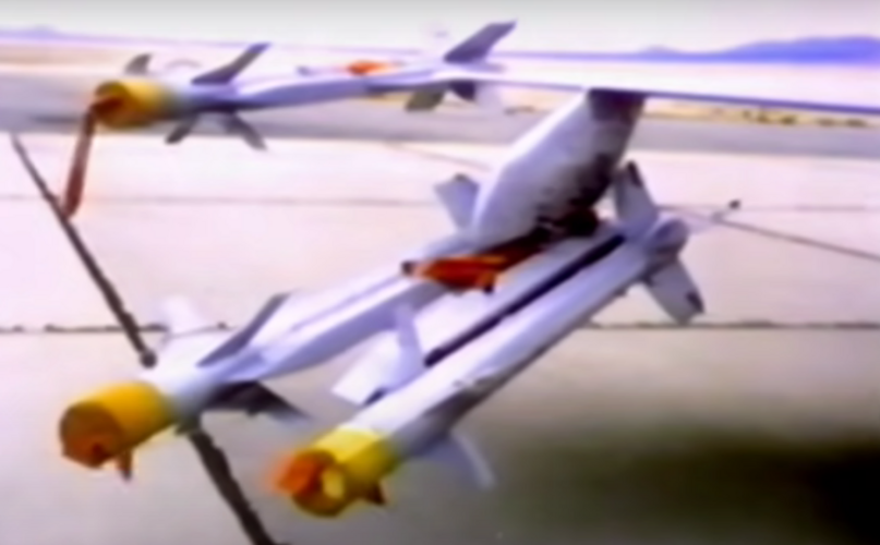
I have another more in-depth inquiry with the F-20, specifically relating to the dual Sidewinder/AMRAAM mounts that was proposed/shown off (in mockup form) in the sales film: What adapter/rails would've been used?
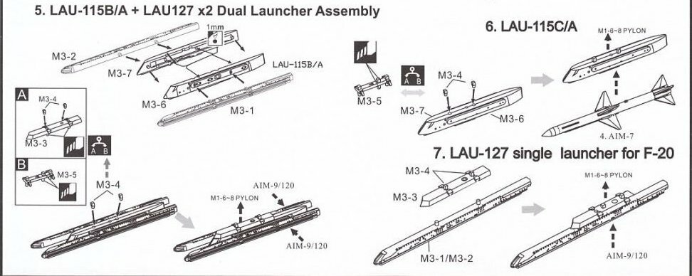
The closest I've found to what was shown on the mockup is this little section from model kit instructions, which shows the LAU-115C/A adapter and LAU-127B/A rails. Would these be the correct systems, or is it just an assumption by the model kit's company?
Attachments
HB Stratos
ACCESS: Restricted
- Joined
- 27 November 2024
- Messages
- 7
- Reaction score
- 15
Hi everyone!
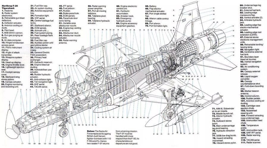
This was an awesome thread to read through. So much useful information, and at long last a few okay resolution blueprints of the F-20 on which top and side view do not contradict each other.
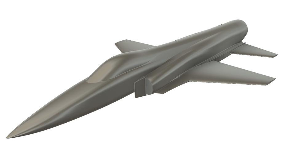
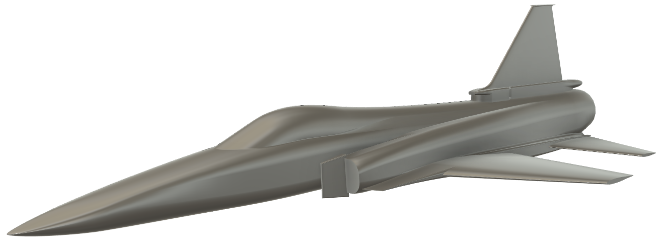
As I'm currently working on a 3d model of this aircraft:
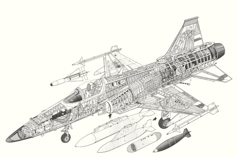
Has anyone ever found cross-section drawings of the F-20?
They appear to be entirely absent from the internet.
Tigershark 30-82
ACCESS: Restricted
- Joined
- 9 March 2021
- Messages
- 19
- Reaction score
- 38
There should be some really good ones in the book Air Force Legends #228: F-20 Tigershark, by Paul Metz. Unfortunately though, they are not digital, so I don't know if they'd be much useHi everyone!
This was an awesome thread to read through. So much useful information, and at long last a few okay resolution blueprints of the F-20 on which top and side view do not contradict each other.
As I'm currently working on a 3d model of this aircraft:
Has anyone ever found cross-section drawings of the F-20?
They appear to be entirely absent from the internet.
- Joined
- 27 December 2005
- Messages
- 17,734
- Reaction score
- 26,293
I can check my copy of Air Force Legends #228: F-20 Tigershark, by Paul Metz, can probably get a copy of any useful drawing from the researcher/coauthor.Hi everyone!
This was an awesome thread to read through. So much useful information, and at long last a few okay resolution blueprints of the F-20 on which top and side view do not contradict each other.
As I'm currently working on a 3d model of this aircraft:
Has anyone ever found cross-section drawings of the F-20?
They appear to be entirely absent from the internet.
- Joined
- 2 August 2006
- Messages
- 3,255
- Reaction score
- 1,527
If you could get me a copy of the last big wing layout as shown on page 113 that would be great.I can check my copy of Air Force Legends #228: F-20 Tigershark, by Paul Metz, can probably get a copy of any useful drawing from the researcher/coauthor.
- Joined
- 27 December 2005
- Messages
- 17,734
- Reaction score
- 26,293
This isn't an all you can eat buffet 
- Joined
- 27 December 2005
- Messages
- 17,734
- Reaction score
- 26,293
Okay so
P104 - P105 has side view drawings of F-5G (1979), F-20A Proposed Production (1983) and F-20 Proposed Production (1986), which are the basis of Tigershark 1, 2 &3, and 4 respectively. P106 has a plan view of the 1986 configuration and P107 section cuts for the 1986 configuration.
Many many other drawings showing details.
- Joined
- 27 December 2005
- Messages
- 17,734
- Reaction score
- 26,293
To be clear, this is not the same drawing as in the book.hope it helps
HB Stratos
ACCESS: Restricted
- Joined
- 27 November 2024
- Messages
- 7
- Reaction score
- 15
I can check my copy of Air Force Legends #228: F-20 Tigershark, by Paul Metz, can probably get a copy of any useful drawing from the researcher/coauthor.
This would be really useful to have! Finally there would be some useable drawings for the F-20 available. I've made good progress on my F-20 model in the meantime, but it'd be nice to have more accurate blueprints to check my work.
Attachments
- Joined
- 27 December 2005
- Messages
- 17,734
- Reaction score
- 26,293
The first thing to note is, which version are you building? Prototype 1, 2&3 and 4 were all different from each other.This would be really useful to have! Finally there would be some useable drawings for the F-20 available. I've made good progress on my F-20 model in the meantime, but it'd be nice to have more accurate blueprints to check my work.
HB Stratos
ACCESS: Restricted
- Joined
- 27 November 2024
- Messages
- 7
- Reaction score
- 15
The first thing to note is, which version are you building? Prototype 1, 2&3 and 4 were all different from each other.
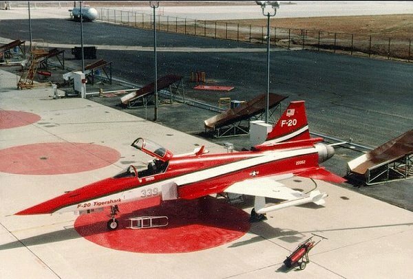
I've noticed this and it has been quite annoying. I'm building the only prototype that still exists in the california science center as that's the one I can find the most pictures of. Which are still not many pictures, but at least one walkaround that has proven incredibly useful. According to wikipedia, that airframe is prototype 3.
These are the pictures I am working off of:

Northrop F-20 Tigershark - Fotos & Video
The Northrop F-20 Tigershark was a light fighter aircraft that was developed by Northrop in the 1970s and 1980s - _Deutsch
www.net-maquettes.com
HB Stratos
ACCESS: Restricted
- Joined
- 27 November 2024
- Messages
- 7
- Reaction score
- 15
I somehow only now noticed that this isn't the low quality inboard scan that can be found in some places of the internet, but a version with much higher resolution, quality and more complete cross-sections. That is very useful to have, thank you so much for sharing!hope it helps
- Joined
- 27 December 2005
- Messages
- 17,734
- Reaction score
- 26,293
You really need a copy of the book. Prototype 4 was going to be the intended production standard version. I have some more section drawings to share.
HB Stratos
ACCESS: Restricted
- Joined
- 27 November 2024
- Messages
- 7
- Reaction score
- 15
You really need a copy of the book. Prototype 4 was going to be the intended production standard version. I have some more section drawings to share.
The book would probably be quite helpful. I don't have much to spare at the moment, but I'll have a think about it. Any drawings you can share would definitely be really useful for me, so if you can please do post them!
- Joined
- 24 November 2008
- Messages
- 1,549
- Reaction score
- 2,606
Looking good! What 3D modeling software are you using?This would be really useful to have! Finally there would be some useable drawings for the F-20 available. I've made good progress on my F-20 model in the meantime, but it'd be nice to have more accurate blueprints to check my work.
- Joined
- 27 December 2005
- Messages
- 17,734
- Reaction score
- 26,293
High resolution section drawings were supplied for modelling purposes. If anyone else needs them, send me a private message (conversation).
- Joined
- 1 April 2006
- Messages
- 11,373
- Reaction score
- 10,197
HB Stratos
ACCESS: Restricted
- Joined
- 27 November 2024
- Messages
- 7
- Reaction score
- 15
Fusion 360. By some accounts not the best software for this, but it's the tool I know, and I like my parametric designLooking good! What 3D modeling software are you using?
HB Stratos
ACCESS: Restricted
- Joined
- 27 November 2024
- Messages
- 7
- Reaction score
- 15
Made some more progress on my model. It now closely follows prototype 3 (except for wing planform adjustments I still need to make and RWR receivers on the parachute as well as intakes on the VTP base) and in my opinion it looks pretty darn sleek. what a cool aircraft. All hail parametric design for making it relatively easy to adjust the nose to the new shape with just a few reference shapes. It sure took long to learn how to model in a stable way that doesn't explode when doing this, but it has paid off a lot.
Though, something I've not found many references on have been the intake splitter plates. Their bottom appears to curve in slightly, while the top appears to be a bent sheet too with a backing plate that guides the boundary layer splitter air. Though shape wise I'm not fully sure how exactly that was constructed and there are few pictures out there.
Does anyone here happen to have detailed insights into the splitter plate design on the F-20?
Attachments
Tigershark 30-82
ACCESS: Restricted
- Joined
- 9 March 2021
- Messages
- 19
- Reaction score
- 38
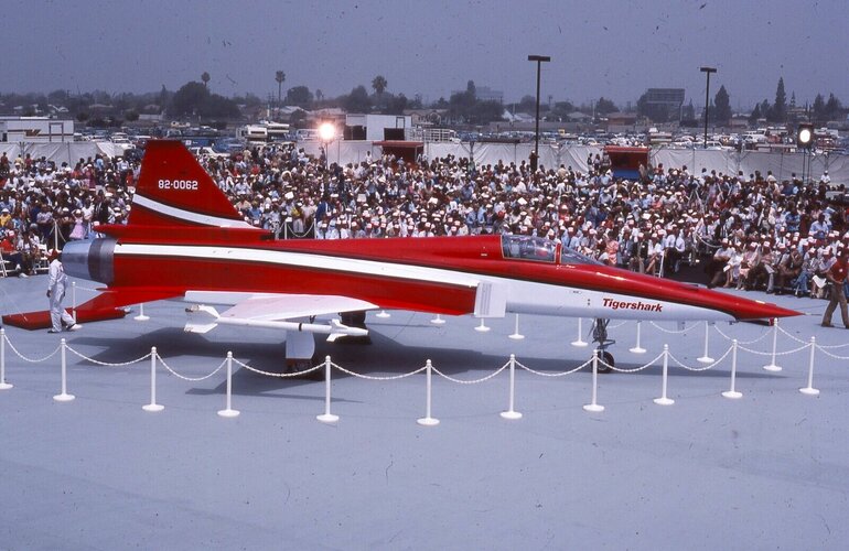
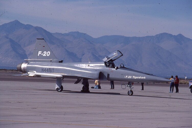
Extraordinarily dumb question, but what colors did each F-20 livery use?
I know of the one that used Mercedes Benz Anthracite Grey, but I'm not sure for the other three (or possibly 4) liveries...
I know of the one that used Mercedes Benz Anthracite Grey, but I'm not sure for the other three (or possibly 4) liveries...
Similar threads
-
A
-
Lockheed CL-1200 / X-27 Lancer
- Started by overscan (PaulMM)
- Replies: 84
-
-
US Army's 1990s Armored Systems Modernization (ASM) Program (FIFV, Block III Tank, Crusader)
- Started by RyanC
- Replies: 77
-

