In many high performance flight vehicles maneuverability is a prized performance characteristic. Such flight Vehicles frequently are fired at targets that are themselves highly maneuverable. The targets, understandably, Seldom wait for the flight vehicle and try to evade it. This is a much greater concern to the flight vehicle as it approaches the target because Shorter distances yield Shorter reaction times. Sometimes, these flight vehicles are themselves fired upon. In these situations, maneuverability may be desired to help evade the weapon fired at them. Designers frequently choose larger fins for greater maneuverability over Small fins for Speed in these types of flight vehicles.
One attempt to compensate for these kinds of tradeoffs experiments with motor technologies. Rocket motors be categorized in a number of ways, e.g., by whether they employ solid fuel or liquid fuel. Traditionally, solid rocket motors burned in Stages, and once per Stage. Submarine based ICBMs are classic examples of this technology. More recently, Some rockets have employed what are known as “dual pulse' motors that burn twice per Stage, although their practical applications are still relatively rare. The Boeing Company's AGM-69-A Short Range Attack Missile (“SRAM”) II and Lockheed Martin Corporation's Javelin shoulder launched missile Systems are examples. Dual pulse motors have been found useful in improving range, alleviating thermal problems, and achieving higher end Speed.
Conventional uses of dual pulse motors cause other problems, however. For example, the increased high end Speed exacerbates the problem of decreased reaction time. Another approach to providing terminal maneuverability is to provide what are known as “divert motors.” Divert motors are essentially side facing thrusters. The principal consequence of the divert motors is to move the missile Sideways, bodily, relative to the current heading, as represented by the arrow 108. Divert motors are a separate System that can cause complications, Such as difficulty in integrating into the control systems of the missile . The divert motors also add cost and weight to the missile 100, and generally decrease the reliability of the overall missile System. The present invention is directed to resolving, or at least reducing, one or all of the problems mentioned above.
The present invention, in its various aspects and embodiments, includes method and apparatus for thrust vectoring a flight vehicle during homing. The flight vehicle comprises a body; a plurality of attitude control mechanisms on the body; a multi-pulse motor housed at least partially in the body; and a control unit housed in the body. The control unit generates Signals controlling an actuation of the attitude control mechanisms and the multi-pulse motor to initiate a follow-on burn of the multi-pulse motor to effect a maneuver directed by the actuation of the attitude control mechanisms. The method comprises conserving a Second burn of a dual pulse motor until target acquisition; acquiring a target; actuating a attitude control mechanism for the flight vehicle to alter the flight vehicle's heading, and initiating the second burn...
The flight vehicle, in the illustrated embodiment, is an interceptor missile. In operation, the flight vehicle performs a mission profile in two phases. In the first phase, the flight vehicle locates and acquires the target before entering the Second phase, wherein it homes in on the target. The multi-pulse motor burns its fuel in two pulses, just as does any other dual pulse motor. However, the present invention, through the control algorithm encoded on the program Storage medium and executed by the computing device , conserves the Second pulse of the burn until the Second phase of the mission profile. More particularly, in the illustrated invention, the multi pulse motor A30 is a solid-fueled, dual pulse motor.
As shown in FIG. 3, the present invention begins by conserving a second burn of a multi-pulse motor until target acquisition . Eventually, the flight vehicle acquires a target. This conservation is performed by the control unit , through the execution of the software control algorithm encoded on the program Storage medium by the computing device . Target acquisition may be made by any technique known to the art. AS used herein, the term “target acquisition' means location of the target by the onboard sensors of the flight vehicle . Furthermore, target acquisition marks the point at which the flight vehicle begins “homing” on the target. As used herein, the term “homing” identifies that part of the mission that follows target acquisition.
As is shown in FIG. 4A, the flight vehicle will be moving on a first flight path. Typically, the flight vehicle will need a new flight path, e.g., the flight path 405, to intercept or strike the target. The flight vehicle is shown oriented in the direction of the first flight path 400 at the time of target acquisition, but this may not always be the case. Note that there is no burn from the multi-pulse motor 230 shown in FIG. 4A.
To achieve the new flight path 405, the flight vehicle 200 actuates an attitude control mechanism, e.g., a control Surface 220 (at 315) for the flight vehicle 200, as indicated by the arrow 415 in FIG. 4B, to alter the current flight path 400 of the flight vehicle 200 to the new flight path 405. Although only the one control Surface 220 is indicated as being actuated, any maneuver will typically include actuation of two, three, or more attitude control mechanisms. The deter mination of which attitude control mechanisms are actuated will depend on the combination of change in pitch, yaw, and roll needed to perform the desired maneuver. These details will be implementation Specific and may be implemented in accordance with conventional practice. Note that, in Some Scenarios, the attitude control mechanism may already be actuated for the effectuation of a previously desired maneu ver Such that the attitude control mechanism may already by actuated when the target is acquired. Thus, the actuation of the attitude control mechanism (at 315) upon target acqui Sition does not preclude prior actuation.
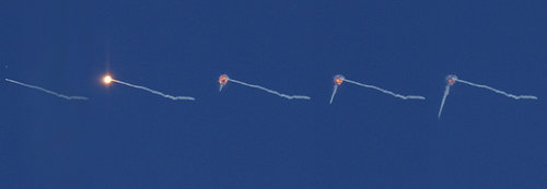
The flight vehicle 200 also initiates the second burn for the multi-pulse motor 230 (at 320). Note that the initiation of the second burn is indicated in FIG. 4B and in FIG. 4C by the plume 420. The second burn generates a vectored thrust that generates a relatively large "Sideways' thrust component (represented by the arrow 425 in FIG. 4C) as the heading of the flight vehicle 200 changes. The vectored thrust 425 alters the flight path of the flight vehicle 200 in the direction of the new flight path 405.
Note that the illustrated embodiment initiates the second burn not only after target acquisition, but also after actuation of the control Surface 220. However, the invention is not so limited. The Second burn may be initiated after target acquisition but before actuation of the control Surface 220, for instance. Furthermore, the illustrated embodiment only changes the heading of the flight vehicle 200 until it is consonant with the new flight path 405. Some alternative embodiments may choose to control the heading of the flight vehicle 200 temporarily beyond the direction of the new flight path. This will generate a vectored thrust that will more quickly maneuver the flight vehicle 200 to the new flight path 405. However, the heading will need to be corrected back in a timely fashion to the new flight path 405 to prevent “overshooting” the new flight path 405. The vectored thrust of the second burn permits the use of smaller, lighter fins 250. Although the drawings are not necessarily to Scale, the difference is illustrated by compar ing the size of the fins 104 relative the overall size of the flight vehicle 100 in FIG. 1 and the size of the fins 250 relative to the overall size of the flight vehicle 200 in, e.g., FIG. 4A. The invention in this embodiment consequently realizes both the Speed and weight advantages of using Smaller fins with the range, thermal loading, and Speed advantages of dual pulse motors without incurring the complexity of using divert motors. Indeed, simulations have shown that the invention may have a relatively extraordinary beneficial impact on the maneuverability of Such a flight vehicle. Furthermore, the increase in Speed does not adversely affect target acquisition time Since the acceleration occurs after target acquisition. Note also that, although the invention permits the use of Smaller, lighter fins, this is not required. The invention may be employed with fins of conventional size in Some embodiments.
AS was noted earlier, liquid-fueled motors may be burned Several times. In theory, Solid-fuel motors can also be constructed to achieve more than two burns by further Segmenting the propellant Supply. Thus, Some embodiments might not be limited to a “first burn and a “second burn.”..


