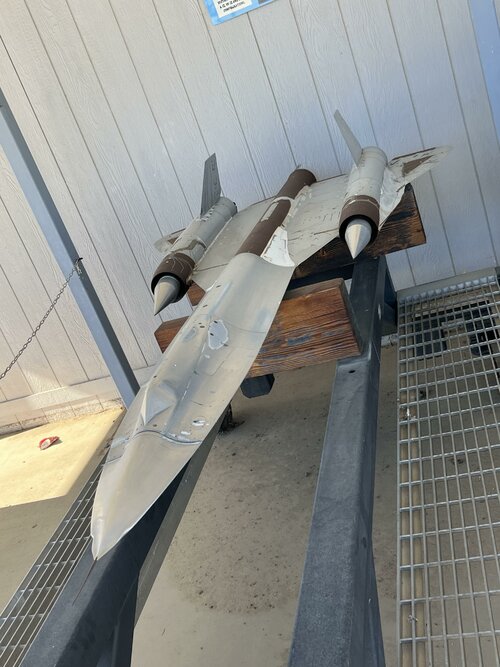
One of the craziest ejection ever (not sure "ejection" is the correct word). With the Soviet pilot at Le Bourget '89, and the few people that survived 25 000 ft freefalls... without parachutes (Yugoslavia stewardess, that B-17 crew who landed in a railway station, and a few others). Also that F-100 pilot, first to bail out at supersonic speed.
You are using an out of date browser. It may not display this or other websites correctly.
You should upgrade or use an alternative browser.
You should upgrade or use an alternative browser.
Lockheed A-12 and SR-71 projects
- Thread starter SOC
- Start date
-
- Tags
- aerospace defense command air defence air defense command central intelligence agency cold war general electric aircraft engines lockheed nuclear battlefield pratt & whitney sead skunk works strategic air command strategic bomber strategic defence strategic reconnaissance united states united states air force united states navy
Scott Kenny
ACCESS: USAP
- Joined
- 15 May 2023
- Messages
- 11,078
- Reaction score
- 13,312
From things posted by former Blackbird pilots on the HabuBrats SR71 facebook group, the airframe limitation was Mach 3.55, where the inlet spikes ran out of travel and the nose shock touches the ailerons. But usually the engines reached their max inlet temperature before then.FighterJock said:So what was faster in terms of overall speed? A-12 or SR-71A? I have heard many stories over the years that the SR-71A was faster than the A-12, could someone clear this up for me. :-\
From COMIREX-D-12.1/1 (Approved for release Date: Aug 2007)
I would interpret the equality of Mach numbers listed as a propulsion system limitation.
Scott Kenny
ACCESS: USAP
- Joined
- 15 May 2023
- Messages
- 11,078
- Reaction score
- 13,312
The last Blackbird flight was from LA to DC, not the other way around.sferrin said:Ian33 said:sublight is back said:What is the aircraft in figure 1 that goes Mach 6 @ 120k feet?
The one that was flying way higher and and far faster than the SR71 as it was doing a sprint run across the USA would be my guess.
The crew mused iver the fact that their last high speed flight was indeed a cover for a classified airframe test.
What?Do you have anymore details on this? Which crew? Book? Interview?
In a nutshell, the crew were doing a sprint across the USA, down to the South West. The crew were in contact with a ground control team for the effort. When they asked for altitude and airspeed, the controller replied with a mach 4+ airspeed and 20,000 feet above them. When they queried the height and speed they got a flustered response with tbe Blackbirds correct details. They basically then said 'our last run, our bow out, was just a cover for a covert high speed test going on high over the tops of us.
- Joined
- 24 January 2006
- Messages
- 1,320
- Reaction score
- 459
The last Blackbird flight was from LA to DC, not the other way around.
If you mean the flight of 17972 from LA to DC in 68 minutes, that was on 6 March 1990. That was definitely not the last Blackbird flight. NASA flew them for a while afterwards, and then later in the 1990s there was the brief reactivation by the USAF. The last USAF flight was 10 October 1997. The last ever Blackbird flight was 9 October 1999, a NASA flight.
aonestudio
I really should change my personal text
- Joined
- 11 March 2018
- Messages
- 2,959
- Reaction score
- 7,454
- Joined
- 6 November 2010
- Messages
- 5,201
- Reaction score
- 5,357
aonestudio
I really should change my personal text
- Joined
- 11 March 2018
- Messages
- 2,959
- Reaction score
- 7,454
Huh high G and SR-71?!?

 hushkit.net
Just remind yourself that those G-load are what you would get out of GA (Cessna 172 etc...).
In general, the SR-71 was limited to 1.5 g and 45 degrees of bank while flying Mach 3 and greater; 2 g between 64,000 and 80,000 pounds of fuel; 2.5 g below 64,000 pounds of fuel; and 3.5 g at low altitude (below 50,000 feet) and less than 30,000 pounds of fuel.

DECLASSIFIED: Spying at Mach 3+: our Interview with SR-71 Blackbird pilot reveals how US lured North Korea to shoot missiles
From the 1960s until the 1990s the US spied on whoever it liked with impunity from the snapping cameras and greedy sensors of the fastest aeroplane ever to take off from a runway, the spectacular S…
Just remind yourself that those G-load are what you would get out of GA (Cessna 172 etc...).
- Joined
- 2 May 2007
- Messages
- 481
- Reaction score
- 1,912
Huh high G and SR-71?!?
Everything's relative, I suppose! Relevant part of Frank Murray's excellent Oxcart talk linked below (59m:14s or so). If you haven't watched it before it's well worth setting aside the time.
"It's a long skinny thing, built like a butterfly. It is not very strong; it's only a 2g airframe. 2g! Get that! You know, you're pullin' more'n that pulling up at the stop-light down here at Sears! So that's not much."
Last edited:
Christopher Wang
ACCESS: Secret
- Joined
- 3 June 2021
- Messages
- 272
- Reaction score
- 573
It is hard to read, but the study also proposed to replace the SR-71 Blackbird's Pratt & Whitney J58 afterburning turbojets with either the Pratt & Whitney F100 or General Electric F101 afterburning turbofans as shown above in the lower-right text box ["NEWER ENGINES (F-100, F-101)"].
Last edited:
The split plan view shown above looks like it came directly from the Revell YF.12 model kit instruction sheet slightly modified around the nose but still identifiable (right down to the inner wing 'probes') 
Last edited:
- Joined
- 29 July 2009
- Messages
- 1,752
- Reaction score
- 2,395
Compilation of interviews regarding the YF-12, how it got funded and why and how it was developed, and the A-12 and SR-71 programs.
View: https://www.youtube.com/watch?v=waIKmfA-lP8&t=790s
Last edited:
blackkite
Don't laugh, don't cry, don't even curse, but.....
- Joined
- 31 May 2007
- Messages
- 8,784
- Reaction score
- 7,573
Hi!

 www.thedrive.com

SR-71 Blackbird’s Predecessor Looked Even Cooler With Canards
An early design of the SR-71's predecessor had massive canard foreplanes. This is what it would've looked like if it had flown.
walk-around photos of Lockheed SR-71 & A-12
walk-around photos of Lockheed SR-71 & A-12
nabe3saviation.web.fc2.com
Attachments
Last edited:
BlackBat242
OK, I changed my personal text ;)
- Joined
- 10 April 2013
- Messages
- 1,423
- Reaction score
- 4,050
The tip vortices generated by those canards would be perfectly positioned to disrupt the airflow into the engines and cause loss of thrust and frequent unstarts.Hi!

SR-71 Blackbird’s Predecessor Looked Even Cooler With Canards
An early design of the SR-71's predecessor had massive canard foreplanes. This is what it would've looked like if it had flown.www.thedrive.com
walk-around photos of Lockheed SR-71 & A-12
walk-around photos of Lockheed SR-71 & A-12nabe3saviation.web.fc2.com
Hence their disappearance as soon as any real engineer looked at the plan.
Forest Green
ACCESS: Above Top Secret
- Joined
- 11 June 2019
- Messages
- 9,280
- Reaction score
- 16,784
Desert Watchdog
Lex Parsimoniae
- Joined
- 9 August 2009
- Messages
- 43
- Reaction score
- 62
Wasn't there a more in-depth video about how the 71's needed to game out their ops for training to give them a chance, then turning it up when the fighter pilots got too cocky?
blackkite
Don't laugh, don't cry, don't even curse, but.....
- Joined
- 31 May 2007
- Messages
- 8,784
- Reaction score
- 7,573
Hi!

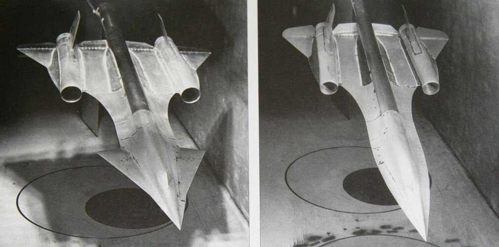
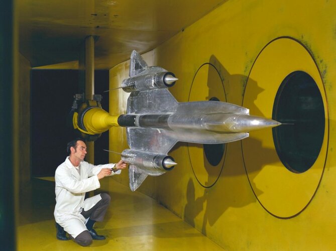
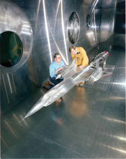
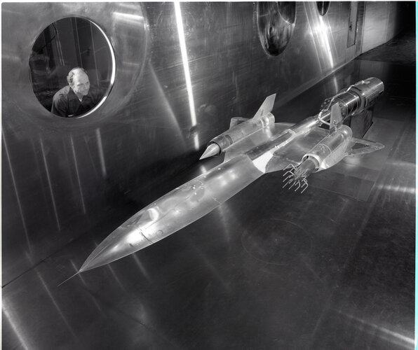
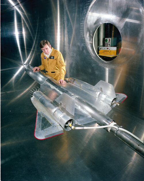
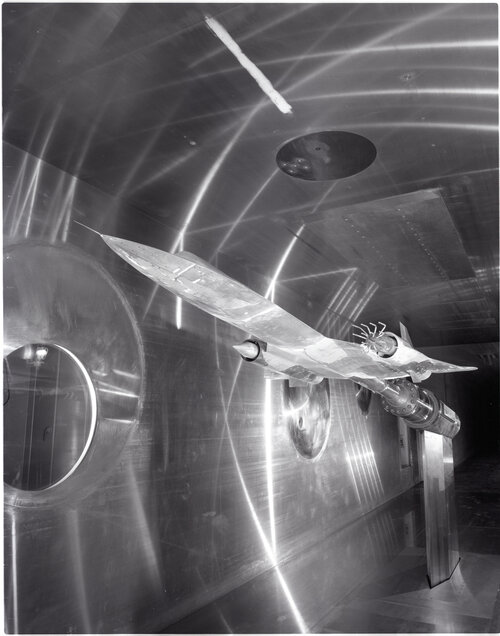
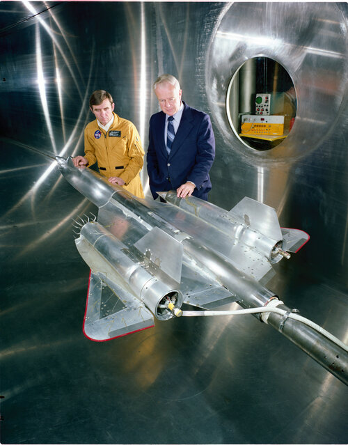
View: https://www.reddit.com/r/aviation/comments/mm04dk/lockheed_engineers_testing_a_scale_model_of_the/#lightbox

Oxcart/Blackbird Wind-Tunnel Test Models - Aviation Humor
What I’d give to have one of those original wind tunnel models hanging from my ceiling. Lockheed A-12 (SR-71 Blackbird predecessor) wind-tunnel test models at NASA Langley, showing an interesting canard configuration as well as the more familiar configuration that was ultimately used. Seeing a...
aviationhumor.net
View: https://www.reddit.com/r/aviation/comments/mm04dk/lockheed_engineers_testing_a_scale_model_of_the/#lightbox
Attachments
-
 Blackbird-wind-tunnel-test-models-1024x507.jpg78.6 KB · Views: 40
 -
 YF-12-inlet-airframe-interaction-test.jpg77.2 KB · Views: 38
 -
 yf-12-aircraft-model-in-the-10x10-foot-wind-tunnel-66b126.jpg779 KB · Views: 35
 -
 yf-12-aircraft-model-in-the-10x10-foot-wind-tunnel-79a5ef.jpg500.2 KB · Views: 37
 -
 yf-12-aircraft-model-in-the-10x10-foot-wind-tunnel-a5d9bc.jpg813.7 KB · Views: 35
 -
 yf-12-aircraft-model-in-the-10x10-foot-wind-tunnel-c4c5af.jpg441.2 KB · Views: 32
 -
 yf-12-aircraft-model-in-the-10x10-foot-wind-tunnel-c06018.jpg814.1 KB · Views: 31
 -
 etnjwjw7nqr61.png287 KB · Views: 40
Last edited:
blackkite
Don't laugh, don't cry, don't even curse, but.....
- Joined
- 31 May 2007
- Messages
- 8,784
- Reaction score
- 7,573
red admiral
ACCESS: Top Secret
- Joined
- 16 September 2006
- Messages
- 1,767
- Reaction score
- 2,252
Has anyone seen any information on why the YF-12 had the twin IRST configuration in the forebody chines?
I'm wondering whether it was simply down to available space:
I'm wondering whether it was simply down to available space:
- Top mounted F-106 style isn't possible because there isn't room between the radar and the cockpit front. The bulkhead for the radar support is the front cockpit bulkhead.
- Bottom mounted Centreline forward of the nose gear isn't possible due to the radar equipment being mounted in the forward bit, and then what looks like cockpit equipment further after.
- Bottom mounted Centreline aft of nose gear not desired due to FOD risk
- Hence off Centreline somewhere is needed, and due to the fairly wide forward fuselage this drives a need for 2 systems in order to maintain coverage across the forward sector either side of the nose
- Joined
- 27 December 2005
- Messages
- 17,666
- Reaction score
- 25,722
They were intended to be able to triangulate for range, which required two separated units some distance apart.
Topic on US IRSTs here - https://www.secretprojects.co.uk/threads/us-irst-devices-an-aaa-4-an-aas-15-and-more.6370/
Topic on US IRSTs here - https://www.secretprojects.co.uk/threads/us-irst-devices-an-aaa-4-an-aas-15-and-more.6370/
Last edited:
red admiral
ACCESS: Top Secret
- Joined
- 16 September 2006
- Messages
- 1,767
- Reaction score
- 2,252
CheersThey were intended to be able to triangulate for range, which required two separated units some distance apart.
Topic on US IRSTs here - https://www.secretprojects.co.uk/threads/us-irst-devices-an-aaa-4-an-aas-15-and-more.6370/
Seems more the intent behind two systems was for the ability to have track whilst scan as a single unit couldn't do both of these at the same time.
There seems an aim to be able to do triangulation, but I can only see how this would be possible at very short ranges as the baselength is so small.
Scott Kenny
ACCESS: USAP
- Joined
- 15 May 2023
- Messages
- 11,078
- Reaction score
- 13,312
You realize that baselength from edge of chine to edge of chine is 12-15ft, right? Which was good enough for at least 20 nautical miles range-finding on ships...Cheers
Seems more the intent behind two systems was for the ability to have track whilst scan as a single unit couldn't do both of these at the same time.
There seems an aim to be able to do triangulation, but I can only see how this would be possible at very short ranges as the baselength is so small.
red admiral
ACCESS: Top Secret
- Joined
- 16 September 2006
- Messages
- 1,767
- Reaction score
- 2,252
That's the analogy I was thinking about. But the IR sensors have longer wavelength than visible light so resolution will decrease and hence angular error increase, so range will decrease. So if the range is down to 5-10nm then I'm not sure I see what the point is.You realize that baselength from edge of chine to edge of chine is 12-15ft, right? Which was good enough for at least 20 nautical miles range-finding on ships...
- Joined
- 27 December 2005
- Messages
- 17,666
- Reaction score
- 25,722
I did some checking, and I can't find where I read that the two IRST were used for triangulation - I'm pretty sure I didn't dream it.
In fact however, a patent for Infra-red rangefinding using atmospheric absorption specifically says its not possible -
Triangulation is not practical for long range determination in air-to-air applications by a single aircraft since no base line of sufficient length necessary for acceptable range accuracy is possible.
It has been said that the MiG-31 IRST does kinematic ranging, which uses one device and comparison of target angles over time as the MiG-31 moves.
Forest Green
ACCESS: Above Top Secret
- Joined
- 11 June 2019
- Messages
- 9,280
- Reaction score
- 16,784
Phase interferometry can do it with a single emitting aircraft.
red admiral
ACCESS: Top Secret
- Joined
- 16 September 2006
- Messages
- 1,767
- Reaction score
- 2,252
It's in the IRST thread you linked to. Seems the stated aim from Wright-Pat rather than anything on whether it was achieved or not, or at what ranges.I did some checking, and I can't find where I read that the two IRST were used for triangulation - I'm pretty sure I didn't dream it.
That IRST thread was pretty interesting from the 180nm detection ranges Vs high altitude, high speed targets even with those older IRSTs.
Is interferometry done for IR on an aircraft though? Definitely for RF (today at least), but it's a technique that depends on accuracy of base distance measurements compared to wavelength, so may not be practicable on a vibrating aircraft that stretches with atmospheric heating etc.Phase interferometry can do it with a single emitting aircraft.
Forest Green
ACCESS: Above Top Secret
- Joined
- 11 June 2019
- Messages
- 9,280
- Reaction score
- 16,784
No, it's done passively by the RWR system based on the other aircraft's radar emissions. The receiver is usually attached in such a place as to avoid the latter. I believe it can also be done by some AESA radar systems in passive mode.Is interferometry done for IR on an aircraft though? Definitely for RF (today at least), but it's a technique that depends on accuracy of base distance measurements compared to wavelength, so may not be practicable on a vibrating aircraft that stretches with atmospheric heating etc.
red admiral
ACCESS: Top Secret
- Joined
- 16 September 2006
- Messages
- 1,767
- Reaction score
- 2,252
@Forest Green That was my question. Doing it at the shorter wavelengths of IR drives much more accurate knowledge of precisely where each IR sensor is. Which may not be feasible on an aircraft.
Scott Kenny
ACCESS: USAP
- Joined
- 15 May 2023
- Messages
- 11,078
- Reaction score
- 13,312
There's ways to control for that. They add weight and complexity, but they exist.@Forest Green That was my question. Doing it at the shorter wavelengths of IR drives much more accurate knowledge of precisely where each IR sensor is. Which may not be feasible on an aircraft.
Nowadays they'd be pretty stupid-cheap to implement and much lighter than in the 1960s. Laser rangefinder, mostly, but those aren't stupid-cheap till the 2000s.
Forest Green
ACCESS: Above Top Secret
- Joined
- 11 June 2019
- Messages
- 9,280
- Reaction score
- 16,784
You could theoretically do it with a staring array IRST but I'm not sure any existing ones actually do.@Forest Green That was my question. Doing it at the shorter wavelengths of IR drives much more accurate knowledge of precisely where each IR sensor is. Which may not be feasible on an aircraft.
Forest Green
ACCESS: Above Top Secret
- Joined
- 11 June 2019
- Messages
- 9,280
- Reaction score
- 16,784
Similar threads
-
-
-
Project ISINGLASS & Project RHEINBERRY
- Started by flateric
- Replies: 374
-
-
Lockheed SR-71/YF-12 Blackbirds (Dennis R. Jenkins)
- Started by overscan (PaulMM)
- Replies: 3


