Junkers Ju 87 - Development, Variants , Related Projects

Here is an interesting overlay - my digitization of the Ju 87 airfoil from the Russian document, overlaid on a Ju 52 airfoil that I found measurements for in
BTW, this thesis contains an error - the Ju 52 flap is normally 2.5 deg nose down, not 0 deg.

Yellow is Ju 52, magenta is Ju 87. The coordinates are on a unit chord, to allow an overlay. As you can see, the airfoils are related, but not the same.
If I may add that this information can only be partial because I suppose it is the root profile, apart from the thickness of the profile which varies up to the salmon of the wing, its coordinates change most of the time. Ex. B-29 extreme wing airfoils ...Camber is crucial and can be scalable !..
 

Attachments

  • b29root-il_l.png
    b29root-il_l.png
    21.3 KB · Views: 42
  • b29tip.gif
    b29tip.gif
    11.2 KB · Views: 32
Hi Tonton,

If I may add that this information can only be partial because I suppose it is the root profile, apart from the thickness of the profile which varies up to the salmon of the wing, its coordinates change most of the time. Ex. B-29 extreme wing airfoils ...Camber is crucial and can be scalable !..

I suppose the tip airfoil is also shown on the Russian diagram ... the caption is illegible, but you can see the washout consistent with the separate washout diagram. (Now that I think about it, one could probably calibrate the aspect ratio of the perspective-corrected diagram with that information.)

What is "salmon of the wing", by the way? I read this as "tip airfoil", but that was only a guess! :)

Regards,

Henning (HoHun)
1688554286755.png
Dear Henning,

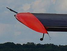
The "salmon" is red on this MH-152 Broussard. I used Reverso for translation but it wasn't a good idea !

Un petit dessin vaut mieux qu'un long discours ... (Napoléon) ;)

Tonton
 
Hi!


Attachments

  • 149341756_1821451341340561_3961667098502900695_n.jpg
    149341756_1821451341340561_3961667098502900695_n.jpg
    16.2 KB · Views: 26
  • 149171530_1821451361340559_7586494902018861002_n.jpg
    149171530_1821451361340559_7586494902018861002_n.jpg
    15.5 KB · Views: 25
  • 149550674_2929236417296776_3078918989133567536_n.jpg
    149550674_2929236417296776_3078918989133567536_n.jpg
    51.6 KB · Views: 29
  • 148862045_2929236450630106_3558810018160331383_n.jpg
    148862045_2929236450630106_3558810018160331383_n.jpg
    41.1 KB · Views: 24
  • 149316533_2929236473963437_3169896606050279891_n.jpg
    149316533_2929236473963437_3169896606050279891_n.jpg
    30.7 KB · Views: 24
  • unnamed.jpg
    unnamed.jpg
    20.6 KB · Views: 25
  • wRuinoh.jpeg
    wRuinoh.jpeg
    82.6 KB · Views: 34
  • kAiy7Mq.jpeg
    kAiy7Mq.jpeg
    95.1 KB · Views: 41
  • giphy.gif
    giphy.gif
    1.1 MB · Views: 35
Last edited:
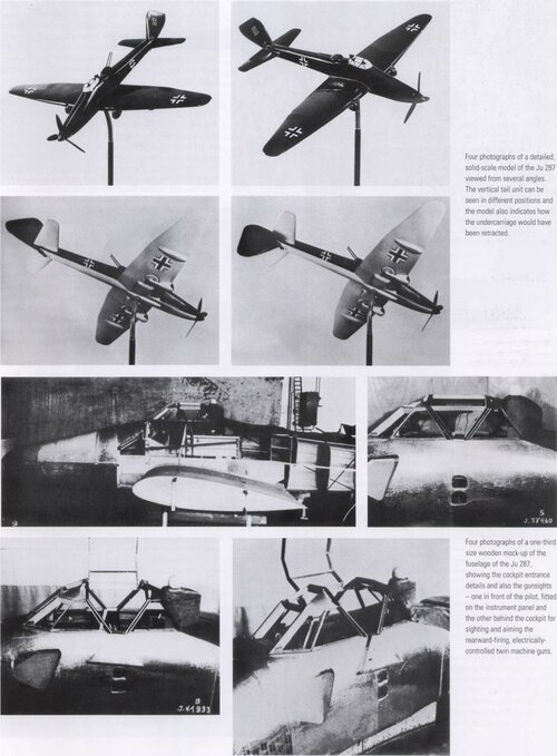
And this is the Ju 187 (see below), about which very little is known. It's really not clear how this fin was supposed to work.​
View attachment 656107
That looks like a Ju 87 windtunnel model that was modified to test the aerodynamics of the proposed configuration. The regular vertical fin and rudder have been simply been moved to the bottom of the fuselage, note that the horizontal stabilizer struts are still affixed.The fixed landing gear has been removed and the cowling reshaped. The vertical fin and rudder of the model not being intended as an accurate physical representation of the movable assembly, just a stand in used to determine possible effects on stability and drag when in the lowered position. Rebuilding an existing windtunnel model isn't unusual.
 
That looks like a Ju 87 windtunnel model that was modified to test the aerodynamics of the proposed configuration. The regular vertical fin and rudder have been simply been moved to the bottom of the fuselage, note that the horizontal stabilizer struts are still affixed.The fixed landing gear has been removed and the cowling reshaped. The vertical fin and rudder of the model not being intended as an accurate physical representation of the movable assembly, just a stand in used to determine possible effects on stability and drag when in the lowered position. Rebuilding an existing windtunnel model isn't unusual.

Seems like a plausible explanation to me.
 

Similar threads

Please donate to support the forum.

Back
Top Bottom